ICGOO在线商城 > YFF21PC1A105M
- 型号: YFF21PC1A105M
- 制造商: TDK
- 库位|库存: xxxx|xxxx
- 要求:
| 数量阶梯 | 香港交货 | 国内含税 |
| +xxxx | $xxxx | ¥xxxx |
查看当月历史价格
查看今年历史价格
YFF21PC1A105M产品简介:
ICGOO电子元器件商城为您提供YFF21PC1A105M由TDK设计生产,在icgoo商城现货销售,并且可以通过原厂、代理商等渠道进行代购。 提供YFF21PC1A105M价格参考¥0.75-¥2.97以及TDKYFF21PC1A105M封装/规格参数等产品信息。 你可以下载YFF21PC1A105M参考资料、Datasheet数据手册功能说明书, 资料中有YFF21PC1A105M详细功能的应用电路图电压和使用方法及教程。
| 参数 | 数值 |
| 产品目录 | |
| DC电阻(DCR) | 12 毫欧最大 |
| 描述 | CAP FEEDTHRU 1UF 10V 0805馈通电容器 1.0uF 10volt +50-10% 2.0x1.25x0.85mm |
| 产品分类 | |
| 品牌 | TDK Corporation |
| 产品手册 | |
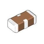
| 产品图片 |
|
| rohs | 符合RoHS无铅 / 符合限制有害物质指令(RoHS)规范要求 |
| 产品系列 | 馈通电容器,TDK YFF21PC1A105MCKD |
| 数据手册 | |
| 产品型号 | YFF21PC1A105M |
| PCN零件编号 | |
| 产品 | Four Terminal Filter Capacitors |
| 产品培训模块 | http://www.digikey.cn/PTM/IndividualPTM.page?site=cn&lang=zhs&ptm=8782 |
| 产品目录绘图 |
|
| 产品目录页面 | |
| 产品种类 | 馈通电容器 |
| 其它名称 | 445-3027-1 |
| 包装 | 剪切带 (CT) |
| 商标 | TDK |
| 外壳宽度 | 1.25 mm |
| 外壳长度 | 2 mm |
| 外壳高度 | 0.85 mm |
| 大小/尺寸 | 0.079" 长 x 0.049" 宽(2.00mm x 1.25mm) |
| 容差 | 20 % |
| 封装 | Reel |
| 封装/外壳 | 0805(2012 公制),4 PC 板 |
| 封装/箱体 | 0805 (2012 metric) |
| 工作温度 | -55°C ~ 85°C |
| 工厂包装数量 | 4000 |
| 接地端子 | 0.4 mm |
| 最大工作温度 | + 85 C |
| 最小工作温度 | - 55 C |
| 标准包装 | 1 |
| 电压 | 10V |
| 电压额定值DC | 10 V |
| 电容 | 1.0µF |
| 电流 | 4A |
| 电流额定值 | 4 A |
| 端接类型 | SMD/SMT |
| 类型 | Three Terminal Filters |
| 系列 | YFF |
| 螺纹尺寸 | - |
| 零件号别名 | CKD510JB1A105S |
| 高度(最大值) | 0.039"(1.00mm) |



(SN).jpg)

- 商务部:美国ITC正式对集成电路等产品启动337调查
- 曝三星4nm工艺存在良率问题 高通将骁龙8 Gen1或转产台积电
- 太阳诱电将投资9.5亿元在常州建新厂生产MLCC 预计2023年完工
- 英特尔发布欧洲新工厂建设计划 深化IDM 2.0 战略
- 台积电先进制程称霸业界 有大客户加持明年业绩稳了
- 达到5530亿美元!SIA预计今年全球半导体销售额将创下新高
- 英特尔拟将自动驾驶子公司Mobileye上市 估值或超500亿美元
- 三星加码芯片和SET,合并消费电子和移动部门,撤换高东真等 CEO
- 三星电子宣布重大人事变动 还合并消费电子和移动部门
- 海关总署:前11个月进口集成电路产品价值2.52万亿元 增长14.8%

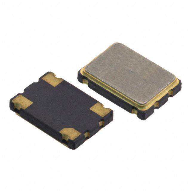
PDF Datasheet 数据手册内容提取
E M C C o m p o n e n t s July 2016 3-TERMINAL FILTERS Feedthrough filter for power line YFF-P series YFF15PC 1005 [0402 inch]* Feedthrough filter YFF18PC 1608 [0603 inch]* Feedthrough filter YFF18PH 1608 [0603 inch]* Feedthrough filter (thickness: 0.8mm) YFF18PW 1608 [0603 inch]* Feedthrough filter (low ESL type) YFF21PC 2012 [0805 inch]* Feedthrough filter YFF31PC 3216 [1206 inch]* Feedthrough filter * Dimensions code JIS[EIA]
(1/9) E M C C o m p o n e n t s 3-TERMINAL FILTERS Conformity to RoHS directive Compatible with lead-free solders Feedthrough filter for power line Overview of YFF-P series FEATURES Small and high-performance EMC components. Good attenuation characteristics in a wide frequency band. For large current (2A to 4A) applications. APPLICATIONS For power lines of of telecommunication terminal devices including smartphones, audio-visual equipment, and information equipment. PART NUMBER CONSTRUCTION YFF 15 PC 0G 435 M T 0 N L x W Rated TDK Capacitance Reel size Internal Series dimensions Product voltage internal Tolerance Taping electrode name internal code code Code mm Code V Code pF Code mm Ni 15 1.0×0.5 PC STD 0G 4 104 100,000 M ±20% 0 ø178 18 1.6×0.8 Thickness 0J 6.3 1,000,000 9 ø330 PH 105 21 2.0×1.2 0.8mm 1A 10 (1.0µF) 31 3.2×1.6 PW Low ESL 1C 16 4,300,000 435 1E 25 (4.3µF) 22,000,000 226 (22µF) PACKAGING STYLE AND SPECIFICATIONS Package quantity (piece/reel) Unit weight Type ø178 ø330 (mm) (mm) (g) YFF15PC 10,000 50,000 0.0008 YFF15PC0G435M 10,000 50,000 0.0015 YFF15PC0G755M 10,000 50,000 0.0027 YFF15PC0G106M 10,000 50,000 0.0029 YFF18PC 4,000 10,000 0.0038 YFF18PH 4,000 10,000 0.0051 YFF18PW 4,000 10,000 0.0038 YFF21PC 4,000 10,000 0.0095 YFF31PC 2,000 10,000 0.0342 RoHS Directive Compliant Product: See the following for more details.https://product.tdk.com/info/en/environment/rohs/index.html Halogen-free: Indicates that Cl content is less than 900ppm, Br content is less than 900ppm, and that the total Cl and Br content is less than 1500ppm. Please be sure to request delivery specifications that provide further details on the features and specifications of the products for proper and safe use. Please note that the contents may change without any prior notice due to reasons such as upgrading. 20160708 / 3tf_commercial_yff-p_en.fm
(2/9) E M C C o m p o n e n t s Overview of YFF-P series RECOMMENDED SOLDERING CONDITION REMINDERS FOR USING THESE PRODUCTS REFLOW SOLDERING Before soldering, be sure to preheat components. The T pre- heating temperature must be 150°C max. with attention paid to Soldering thermal shock. Slow cooling Preheating (Natural cooling) Natural cooling of components in the air is recommended. On the other hand, when dipping them in a solvent for purposes, such as cleaning, make sure that the temperature difference 260˚C max. )C (T) is 100°C. (ure˚ max. When performing hand soldering for circuit modification, apply mperat 50˚C tbhoea rsdo lfdoer ri3n gs eircoonn dtos tohre lceosps.p eTrh efo ilt eamrepae roaft utrhee opf ritnhtee di rocinrc tuipit e 1 T should not exceed 300°C. Use a wrist band to discharge static electricity in your body 0 through the grounding wire. 60 seconds or more 10s max. When incorporating the printed circuit board on which this prod- uct is mounted into a frame, etc., do not apply stress to the prod- HAND SOLDERING uct through local bending of the board by tightening of screws, etc. 300 )C (ure˚ max. perat 0˚C m 5 e 1 T Preheating 0 Make as short as possilble (within three seconds) Please be sure to request delivery specifications that provide further details on the features and specifications of the products for proper and safe use. Please note that the contents may change without any prior notice due to reasons such as upgrading. 20160708 / 3tf_commercial_yff-p_en.fm
(3/9) E M C C o m p o n e n t s YFF-P YFF15PC type series SHAPE & DIMENSIONS RECOMMENDED LAND PATTERN C B 0.19 5 2 GND 0. 4 0 6 W 1 3 0. Land pattern+Solder resist IN/OUT OUT/IN 5 2 Land pattern 0.30 0.70 0. 2 Dimensions in mm GND L T Part No. L (mm) W (mm) T (mm) B (mm) C (mm) YFF15PC0G106MT00□N 1.00±0.20 0.50±0.20 0.50±0.15 0.07min. 0.35±0.10 YFF15PC0G755MT00□N 1.00±0.20 0.50±0.15 0.50±0.15 0.07min. 0.35±0.10 YFF15PC0G435MT00□N 1.05±0.05 0.65±0.05 0.45±0.05 0.09min. 0.30±0.10 YFF15PC0G105MT00□N 1.00±0.05 0.55±0.05 0.30±0.05 0.09min. 0.30±0.10 YFF15PC0J474MT00□N 1.00±0.05 0.55±0.05 0.30±0.05 0.09min. 0.30±0.10 YFF15PC1A224MT00□N 1.00±0.05 0.55±0.05 0.30±0.05 0.09min. 0.30±0.10 YFF15PC1C104MT00□N 1.00±0.05 0.55±0.05 0.30±0.05 0.09min. 0.30±0.10 * Make sure to connect the GND terminal of this product and the GND of the mounting circuit board by using through holes so that the distance between them is the shortest. ELECTRICAL CHARACTERISTICS CHARACTERISTICS SPECIFICATION TABLES Insertion loss Rated voltage Rated current Operating Storage temperature Part No. 40dB frequency range temperature range range Edc Idc (After mounting) (MHz) (V) (A) (°C) (°C) 0.07 to 1000 4 2 –55 to 85 –55 to 85 YFF15PC0G106MT00□N 0.11 to 1000 4 2 –55 to 85 –55 to 85 YFF15PC0G755MT00□N 0.2 to 1000 4 2 –55 to 85 –55 to 85 YFF15PC0G435MT00□N 0.8 to 1000 4 3 –55 to 105 –55 to 105 YFF15PC0G105MT00□N 2 to 1000 6.3 3 –55 to 105 –55 to 105 YFF15PC0J474MT00□N 4 to 1000 10 3 –55 to 105 –55 to 105 YFF15PC1A224MT00□N 9 to 1000 16 3 –55 to 105 –55 to 105 YFF15PC1C104MT00□N The part numbers are TDK’s standard specification products. : Reel size code, 0 (ø178) or 9 (ø330). ELECTRICAL CHARACTERISTICS GRAPH INSERTION LOSS vs. FREQUENCY CHARACTERISTICS RATED CURRENT vs. TEMPERATURE CHARACTERISTICS (DERATING) 0 5 1C104 10 20 1A224 4 ()sdB30 0J04G74105 ()ntA3 1C104, 1A224, 0J474, 0G105 sertion los456000 0G106 ated curre2 0G435, 0G755, 0G106 n R I70 0G755 1 0G435 80 90 0 0.1 1 10 100 1000 10000 –55 –35 –15 5 25 45 65 85 105 125 Frequency(MHz) Ambient temperature(°C) Please be sure to request delivery specifications that provide further details on the features and specifications of the products for proper and safe use. Please note that the contents may change without any prior notice due to reasons such as upgrading. 20160708 / 3tf_commercial_yff-p_en.fm
(4/9) E M C C o m p o n e n t s YFF-P YFF18PC type series SHAPE & DIMENSIONS RECOMMENDED LAND PATTERN 0.40±0.10 0.10min. 0.40 GND 4 80±0.10 IN/O1UT OU3T/IN 0.60 0.400.40 0. Land pattern+Solder resist 2 GND Land pattern 1.60±0.20 0.60 1.00 Dimensions in mm 0 1 0. ± 0 6 0. * Make sure to connect the GND terminal of this product and the GND of the mounting circuit board by using through holes so that the distance between them is the shortest. ELECTRICAL CHARACTERISTICS CHARACTERISTICS SPECIFICATION TABLES Insertion loss Rated voltage Rated current Operating Storage temperature Part No. 40dB frequency range temperature range range Edc Idc (After mounting) (MHz) (V) (A) (°C) (°C) 0.2 to 1000 6.3 4 –55 to 85 –55 to 85 YFF18PC0J475MT0H□N 0.8 to 1000 6.3 4 –55 to 105 –55 to 105 YFF18PC0J105MT0H□N 2 to 1000 6.3 4 –55 to 125 –55 to 125 YFF18PC0J474MT0H□N 3 to 1000 6.3 4 –55 to 125 –55 to 125 YFF18PC0J224MT0H□N 7 to 1000 16 4 –55 to 125 –55 to 125 YFF18PC1C104MT0H□N The part numbers are TDK’s standard specification products. : Reel size code, 0 (ø178) or 9 (ø330). ELECTRICAL CHARACTERISTICS GRAPH INSERTION LOSS vs. FREQUENCY CHARACTERISTICS RATED CURRENT vs. TEMPERATURE CHARACTERISTICS (DERATING) 0 5 10 1C104 1C104, 0J224, 0J474 20 4 ()sdB30 0J2204J474 ()ntA3 nsertion los456000 0J475 Rated curre2 00JJ140755 I 70 0J105 1 80 90 0 0.1 1 10 100 1000 10000 –55 –35 –15 5 25 45 65 85 105 125 Frequency(MHz) Ambient temperature(°C) Please be sure to request delivery specifications that provide further details on the features and specifications of the products for proper and safe use. Please note that the contents may change without any prior notice due to reasons such as upgrading. 20160708 / 3tf_commercial_yff-p_en.fm
(5/9) E M C C o m p o n e n t s YFF-P YFF18PH type series SHAPE & DIMENSIONS RECOMMENDED LAND PATTERN 0.40±0.10 0.10min. 0.40 GND 4 40 10 0. 80±0. IN/O1UT OU3T/IN 0.60 0.40 Land pattern+Solder resist 0. 2 Land pattern GND 0.60 1.00 Dimensions in mm 1.60±0.20 0 1 0. ± 0 8 0. * Make sure to connect the GND terminal of this product and the GND of the mounting circuit board by using through holes so that the distance between them is the shortest. ELECTRICAL CHARACTERISTICS CHARACTERISTICS SPECIFICATION TABLES Insertion loss Rated voltage Rated current Operating Storage temperature Part No. 40dB frequency range temperature range range Edc Idc (After mounting) (MHz) (V) (A) (°C) (°C) 0.4 to 1000 6.3 4 –55 to 85 –55 to 85 YFF18PH0J225MT00□N 0.8 to 1000 6.3 4 –55 to 105 –55 to 105 YFF18PH0J105MT00□N The part numbers are TDK’s standard specification products. : Reel size code, 0 (ø178) or 9 (ø330). ELECTRICAL CHARACTERISTICS GRAPH INSERTION LOSS vs. FREQUENCY CHARACTERISTICS RATED CURRENT vs. TEMPERATURE CHARACTERISTICS (DERATING) 0 5 10 20 4 0J105 ()sdB30 0J105 ()ntA3 nsertion los456000 0J225 Rated curre2 0J225 I 70 1 80 90 0 0.1 1 10 100 1000 10000 –55 –35 –15 5 25 45 65 85 105 125 Frequency(MHz) Ambient temperature(°C) Please be sure to request delivery specifications that provide further details on the features and specifications of the products for proper and safe use. Please note that the contents may change without any prior notice due to reasons such as upgrading. 20160708 / 3tf_commercial_yff-p_en.fm
(6/9) E M C C o m p o n e n t s YFF-P YFF18PW type series SHAPE & DIMENSIONS RECOMMENDED LAND PATTERN 0.80+–00..1200 0.15±0.10 0.80 GND 0 4 4 0 0 0. 80±0.1 IN/O1UT OU3T/IN 40±0.1 0.40 0.40 Land pattern+Solder resist 0. 0. Land pattern 2 GND 10 0.40 1.20 Dimensions in mm 1.60±0.10 0.± 5 1 0 0. 1 0. ± 0 6 0. * Make sure to connect the GND terminal of this product and the GND of the mounting circuit board by using through holes so that the distance between them is the shortest. ELECTRICAL CHARACTERISTICS CHARACTERISTICS SPECIFICATION TABLES Insertion loss Rated voltage Rated current Operating Storage temperature Part No. 40dB frequency range temperature range range Edc Idc (After mounting) (MHz) (V) (A) (°C) (°C) 0.2 to 2000 6.3 4 –55 to 85 –55 to 85 YFF18PW0J475MT0H□N 0.8 to 2000 6.3 4 –55 to 105 –55 to 105 YFF18PW0J105MT0H□N 2 to 2000 6.3 4 –55 to 125 –55 to 125 YFF18PW0J474MT0H□N The part numbers are TDK’s standard specification products. : Reel size code, 0 (ø178) or 9 (ø330). ELECTRICAL CHARACTERISTICS GRAPH INSERTION LOSS vs. FREQUENCY CHARACTERISTICS RATED CURRENT vs. TEMPERATURE CHARACTERISTICS (DERATING) 0 5 10 0J474 20 4 ()sdB30 0J407J1405 ()ntA3 nsertion los456000 0J475 Rated curre2 00JJ140755 I 70 1 80 90 0 0.1 1 10 100 1000 10000 –55 –35 –15 5 25 45 65 85 105 125 Frequency(MHz) Ambient temperature(°C) Please be sure to request delivery specifications that provide further details on the features and specifications of the products for proper and safe use. Please note that the contents may change without any prior notice due to reasons such as upgrading. 20160708 / 3tf_commercial_yff-p_en.fm
(7/9) E M C C o m p o n e n t s YFF-P YFF21PC type series SHAPE & DIMENSIONS RECOMMENDED LAND PATTERN 0.45±0.15 0.20min. 0.50 GND 4 5 6 20 0. 0. 1 3 0 0 25± IN/OUT OUT/IN 0.8 0.6 1. Land pattern+Solder resist 2 GND Land pattern 0.60 1.40 2.00±0.20 Dimensions in mm 5 1 0. ± 5 8 0. * Make sure to connect the GND terminal of this product and the GND of the mounting circuit board by using through holes so that the distance between them is the shortest. ELECTRICAL CHARACTERISTICS CHARACTERISTICS SPECIFICATION TABLES Insertion loss Rated voltage Rated current Operating Storage temperature Part No. 40dB frequency range temperature range range Edc Idc (After mounting) (MHz) (V) (A) (°C) (°C) 0.04 to 1000 6.3 4 –55 to 85 –55 to 85 YFF21PC0J226MT00□N 0.7 to 1000 10 4 –55 to 85 –55 to 85 YFF21PC1A105MT00□N 2 to 1000 16 2 –55 to 125 –55 to 125 YFF21PC1C474MT00□N 7 to 1000 25 2 –55 to 125 –55 to 125 YFF21PC1E104MT00□N The part numbers are TDK’s standard specification products. : Reel size code, 0 (ø178) or 9 (ø330). ELECTRICAL CHARACTERISTICS GRAPH INSERTION LOSS vs. FREQUENCY CHARACTERISTICS 0 1E104 10 1C474 20 )dB30 1A105 (s os40 on l50 serti60 In 0J226 70 80 90 0.1 1 10 100 1000 10000 Frequency(MHz) Please be sure to request delivery specifications that provide further details on the features and specifications of the products for proper and safe use. Please note that the contents may change without any prior notice due to reasons such as upgrading. 20160708 / 3tf_commercial_yff-p_en.fm
(8/9) E M C C o m p o n e n t s YFF-P YFF31PC type series SHAPE & DIMENSIONS RECOMMENDED LAND PATTERN 0.95±0.25 0.40±0.30 1.40 GND 4 0 9 0. 0 2 0 0 0±0. IN/O1UT OU3T/IN 1.3 0.8 1.6 Land pattern+Solder resist Land pattern 2 1.20 2.50 GND Dimensions in mm 3.20±0.20 0 2 0. ± 0 3 1. * Make sure to connect the GND terminal of this product and the GND of the mounting circuit board by using through holes so that the distance between them is the shortest. ELECTRICAL CHARACTERISTICS CHARACTERISTICS SPECIFICATION TABLES Insertion loss Rated voltage Rated current Operating Storage temperature Part No. 40dB frequency range Edc Idc temperature range range (MHz) (V) (A) (After mounting) (°C) (°C) 0.7 to 1000 16 2 –55 to 125 –55 to 125 YFF31PC1C105MT00□N 2 to 1000 16 2 –55 to 125 –55 to 125 YFF31PC1C474MT00□N 3 to 600 16 2 –55 to 125 –55 to 125 YFF31PC1C224MT00□N 7 to 1000 16 2 –55 to 125 –55 to 125 YFF31PC1C104MT00□N The part numbers are TDK’s standard specification products. : Reel size code, 0 (ø178) or 9 (ø330). ELECTRICAL CHARACTERISTICS GRAPH INSERTION LOSS vs. FREQUENCY CHARACTERISTICS 0 10 1C104 20 1C224 )dB30 1C474 (s 1C105 os40 on l50 serti60 n I 70 80 90 0.1 1 10 100 1000 10000 Frequency(MHz) Please be sure to request delivery specifications that provide further details on the features and specifications of the products for proper and safe use. Please note that the contents may change without any prior notice due to reasons such as upgrading. 20160708 / 3tf_commercial_yff-p_en.fm
(9/9) E M C C o m p o n e n t s YFF-P series Packaging style REEL DIMENSIONS C E B r D W t A Dimensions in mm Dimensions in: mm Reel A B C D E W t r ø178 ø178±2.0 ø60±2.0 ø13±0.5 ø21±0.8 2.0±0.5 9.0±0.3 2.0±0.05 1.0 ø330 ø382 max.(ø330 nom.) ø50 min. ø13±0.5 ø21±0.8 2.0±0.5 10.0±1.5 2.0±0.05 1.0 TAPE DIMENSIONS Paper tape Round sprocket holes J Square punch hole for component mounting E D C B t A H G F Dimensions in: mm Type A B C D E F G H J t YFF15PC 0.62 typ. 1.12 typ. 0.7 max. YFF15PC0G435M 0.75 typ 1.18 typ. 8.00±0.30 3.50±0.05 1.75±0.10 2.00±0.05 2.00±0.05 4.00±0.10 ø1.5+0.1/–0 YFF15PC0G755M 0.75 typ 1.30 typ. 0.8 max. YFF15PC0G106M 0.77 typ. 1.30 typ. YFF18PC YFF18PH 1.10 typ. 1.90 typ. 8.00±0.30 3.50±0.05 1.75±0.10 4.00±0.10 2.00±0.05 4.00±0.10 ø1.5+0.1/–0 1.2 max. YFF18PW YFF21PC 1.50 typ. 2.30 typ. 8.00±0.30 3.50±0.05 1.75±0.10 4.00±0.10 2.00±0.05 4.00±0.10 ø1.5+0.1/–0 1.2 max. Plastic tape Round sprocket holes J Square punch hole for component mounting E D C B t A H G F Q K Dimensions in: mm Type A B C D E F G H J K t Q YFF31PC 1.90 typ. 3.50 typ. 8.0±0.3 3.5±0.05 1.75±0.1 4.00±0.1 2.0±0.05 4.00±0.1 ø1.5+0.1/–0 2.50 max. 0.30 max. ø0.50 max. Please be sure to request delivery specifications that provide further details on the features and specifications of the products for proper and safe use. Please note that the contents may change without any prior notice due to reasons such as upgrading. 20160708 / 3tf_commercial_yff-p_en.fm
Mouser Electronics Authorized Distributor Click to View Pricing, Inventory, Delivery & Lifecycle Information: T DK: YFF21PC1E473M YFF18PW0J105M YFF15PC1C104M YFF31PC1C474M YFF21PC1A105M YFF18PW0J474M YFF15PC1A224M YFF15PC0G105M YFF18PH0J225M YFF15PC0J474M YFF31PC1C104M YFF31PC1C105M YFF31PC0J226M YFF21PC1E104M YFF31PC1C224M YFF21PC1E103M YFF18PH0J105M YFF21PC1E223M YFF21PC1A475M YFF18PC0J475M YFF21PC0J106M YFF21PC1E474M YFF18PW0J475M YFF21PC1A225M YFF21PC0J226M YFF15PC0G435M YFF18PC0J105M YFF18PC0J224M YFF18PC0J474M YFF18PC1C104M YFF21PC1C474M YFF15PC0J105M YFF15PC0G755MT000N YFF15PC0G106MT000N YFF18PC0J105MT0H0N YFF18PC0J475MT0H0N YFF21PC1C474MT000N YFF31PC1C224MT000N YFF18PH0J105MT000N YFF15PC1C104MT000N YFF31PC1C105MT000N YFF18PW0J105MT0H0N YFF15PC0G105MT000N YFF21PC1E104MT000N YFF18PW0J475MT0H0N YFF18PH0J225MT000N YFF21PC0J226MT000N YFF15PC1A224MT000N YFF31PC1C104MT000N YFF15PC0J105MT000N YFF31PC1C474MT000N YFF15PC0J474MT000N YFF18PW0J474MT0H0N YFF21PC1A105MT000N YFF21PC1E473MT000N YFF15PC0G435MT000N YFF21PC1E103MT000N YFF18PC0J474MT0H0N YFF18PC0J224MT0H0N YFF21PC1E223MT000N YFF18PC1C104MT0H0N
 Datasheet下载

