 Datasheet下载
- 型号: YC164-JR-07820RL
- 制造商: YAGEO AMERICA CORPORATION
- 库位|库存: xxxx|xxxx
- 要求:
| 数量阶梯 | 香港交货 | 国内含税 |
| +xxxx | $xxxx | ¥xxxx |
查看当月历史价格
查看今年历史价格
YC164-JR-07820RL产品简介:
ICGOO电子元器件商城为您提供YC164-JR-07820RL由YAGEO AMERICA CORPORATION设计生产,在icgoo商城现货销售,并且可以通过原厂、代理商等渠道进行代购。 YC164-JR-07820RL价格参考。YAGEO AMERICA CORPORATIONYC164-JR-07820RL封装/规格:电阻器网络,阵列, 820 Ohm ±5% 62.5mW Power Per Element Isolated 4 Resistor Network/Array ±200ppm/°C 1206 (3216 Metric), Convex, Long Side Terminals。您可以下载YC164-JR-07820RL参考资料、Datasheet数据手册功能说明书,资料中有YC164-JR-07820RL 详细功能的应用电路图电压和使用方法及教程。
| 参数 | 数值 |
| 产品目录 | |
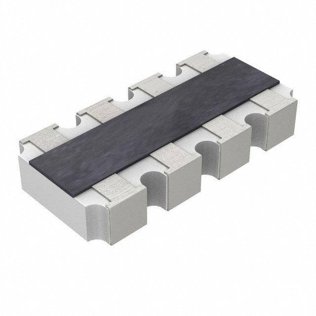
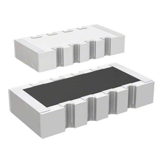
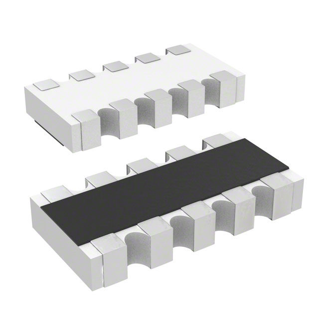
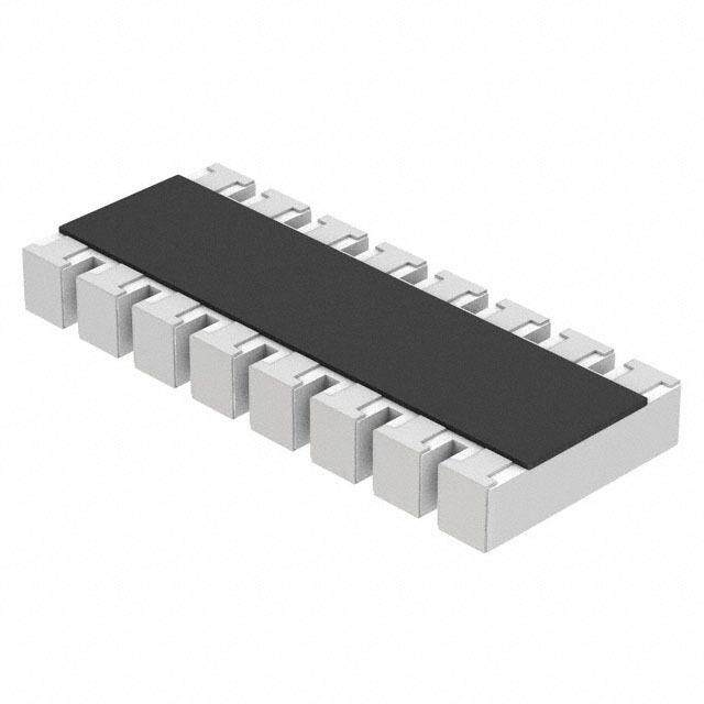
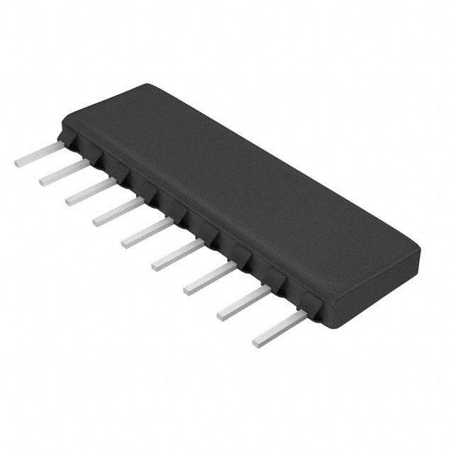
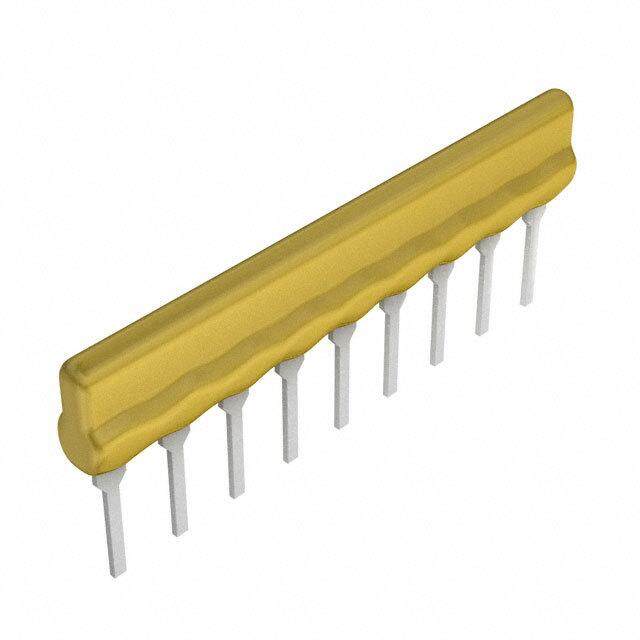
| 描述 | RES ARRAY 820 OHM 4 RES 1206 |
| 产品分类 | |
| 品牌 | Yageo |
| 数据手册 | |
| 产品图片 |
|
| 产品型号 | YC164-JR-07820RL |
| rohs | 无铅 / 符合限制有害物质指令(RoHS)规范要求 |
| 产品系列 | YC164 |
| 产品培训模块 | http://www.digikey.cn/PTM/IndividualPTM.page?site=cn&lang=zhs&ptm=4919 |
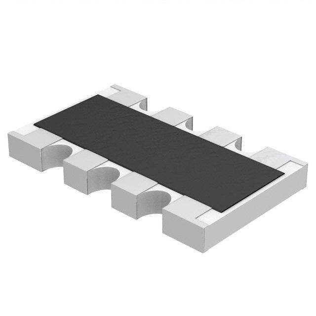
| 产品目录绘图 |
|
| 产品目录页面 | |
| 供应商器件封装 | 0603 |
| 其它名称 | YC164J-820CT |
| 包装 | 剪切带 (CT) |
| 大小/尺寸 | 0.126" 长 x 0.063" 宽(3.20mm x 1.60mm) |
| 安装类型 | 表面贴装 |
| 容差 | ±5% |
| 封装/外壳 | 1206(3216 公制),凸面,长边端子 |
| 工作温度 | -55°C ~ 155°C |
| 应用 | - |
| 引脚数 | 8 |
| 标准包装 | 1 |
| 每元件功率 | 62.5mW |
| 温度系数 | ±200ppm/°C |
| 电路类型 | 隔离 |
| 电阻(Ω) | 820 |
| 电阻器数 | 4 |
| 高度 | 0.028"(0.70mm) |


PDF Datasheet 数据手册内容提取
120 DATA SHEET ARRAY CHIP RESISTORS YC/TC 5%, 1% sizes YC:102/104/122/124/162/164/248/324/158/358 TC: 122/124/164 RoHS compliant 0 V. 4 1 0 2 4, 1 r e b m e v o N – n o ti a c cifi e p s t c u d o r P
Product specification 2 Chip Resistor Surface Mount YC/TC SERIES 102 to 358 12 SCOPE ORDERING INFORM ATIO N - GLOBAL PART NUMBER & 12NC This specification describes Both part numbers are identified by the series, size, tolerance, packing YC (convex) and TC (concave) series type, temperature coefficient, taping reel and resistance value. chip resistor arrays with lead-free YYAAGGEEOO BBRRAANNDD oorrddeerriinngg ccooddee terminations m ade by thick film GLOBAL PART NUMBER (PREFERRED) process. YC XXX – X X X XX XXXX L TC (1) (2) (3) (4) (5) (6) (7) APPLICATIONS (1) SIZE Terminal for SDRAM and YC:102/104/122/124/162/164/248/324/158/358 DDRAM TC: 122/124/164 Computer applications: laptop computer, desktop computer (2) TOLERANCE Consume electronic equipments: PDAs, PNDs F = ±1% J = ±5% (for Jumper ordering, use code of J) Mobile phone, telecom… (3) PACKAGING TYPE R = Paper taping reel K = Embossed plastic tape reel FEATURES (4) TEMPERATURE COEFFICIENT OF RESISTANCE More efficient in pick & place – = Base on spec application Low assembly costs (5) TAPING REEL RoHS compliant 07 = 7 inch dia. Reel 13 = 13 inch dia. Reel Products with lead free terminations meet RoHS ( 6 ) R E S ISTANCE VALUE requirements There are 2~4 digits indicated the resistor value. Letter R/K/M is decimal point. Pb-glass contained in Detailed resistance rules show in table of “Resistance rule of global part number”. electrodes Resistor element and glass (7) DEFAULT CODE are exempted by RoHS Letter L is the system default code for ordering only. (Note) Reducing environmentally hazardous wastes High component and equipment reliability Saving of PCB space Resistance rule of global part ORDERING EXAMPLE None forbidden-materials used number The ordering code of a YC122 in products/production Resistance code rule Example convex chip resistor array, value Halogen Free Epoxy 0R 0R = Jumper 1,000 Ω with ±5% tolerance, 1R = 1 Ω supplied in 7-inch tape reel is: XRXX 1R5 = 1.5 Ω YC122-JR-071KL. (1 to 9.76 Ω) 9R76 = 9.76 Ω NOTE XXRX 10R = 10 Ω 1. All our RSMD products meet RoHS (10 to 97.6 Ω) 97R6 = 97.6 Ω compliant. "LFP" of the internal 2D reel XXXR label mentions "Lead Free Process" 100R = 100 Ω (100 to 976 Ω) 2. On customized label, "LFP" or specific XKXX 1K = 1,000 Ω symbol printed and the optional "L" at (1 to 9.76 KΩ) 9K76 = 9760 Ω the end of GLOBAL PART NUMBER / 12NC can be added (both are on XM 1M = 1,000,000 Ω customer request) (1 MΩ) www.yageo.com Nov. 14, 2014 V.0
Product specification 3 Chip Resistor Surface Mount YC/TC SERIES 102 to 358 12 PP HH YYCCOOMMPP BBRRAANNDD oorrddeerriinngg ccooddeess Both GLOBAL PART NUMBER (preferred) and 12NC (traditional) codes are acceptable to order Phycomp brand produc ts. GLOBAL PART NUMBER (PREFERRED) For detailed information of GLOBAL PART NUMBER and ordering example, please refer to page 2. TC122 series is supplied and ordered by global part number only. 12NC CODE 2350 XXX XXXXX L Last digit of 12NC (1) (2) (3) (4) Resistance decade (3) Last digit TYPE/ START TOL. RESISTANCE PAPER / PE TAPE ON REEL (units) (2) 0.01 to 0.0976 Ω 0 2×0402 IN (1) (%) RANGE 10,000 50,000 0.1 to 0.976 Ω 7 1 to 9.76 Ω 8 ARV321 2350 ±5% 1 to 1 MΩ 013 11xxx 013 12xxx 10 to 97.6 Ω 9 ARV322 2350 ±1% 10 to 1 MΩ 013 2xxxx 013 3xxxx 100 to 976 Ω 1 Jumper 2350 - 0 Ω 013 91001 - 1 to 9.76 KΩ 2 ( 1) The resistors have a 12-digit ordering code starting with 2350. 10 to 97.6 KΩ 3 ( 2) The subsequent 4 or 5 digits indicate the resistor tolerance and 100 to 976 KΩ 4 packaging. 1 to 9.76 MΩ 5 (3) The remaining 4 or 3 digits represent the resistance value with the 10 to 97.6 MΩ 6 last digit indicating the multiplier as shown in the table of “Last digit of 12NC”. Example: 0.02 Ω = 0200 or 200 (4) "L" is optional symbol (Note). 0.3Ω = 3007 or 307 ORDERING EXAMPLE 1Ω = 1008 or 108 The ordering code of a ARV321 resistor, value 1,000Ω with ±5% 33 KΩ = 3303 or 333 tolerance, supplied in tape of 10,000 units per reel is: 235001311102(L) 10 MΩ = 1006 or 106 or YC122-JR-071KL. NOTE 1. All our RSMD products are RoHS compliant. "LFP" of the internal 2D reel label mentions "Lead Free Process" 2. On customized label, "LFP" or specific symbol printed and the optional "L" at the end of GLOBAL PART NUMBER / 12NC can be added (both are on customer request) www.yageo.com Nov. 14, 2014 V.0
Product specification 4 Chip Resistor Surface Mount YC/TC SERIES 102 to 358 12 MARKING YC102/122 No marking Fig. 1 YC 104 No marking F ig. 2 YC 124/16 4/324 1-Digit marking F ig. 3 Jumper=0Ω E-24 series: 3 digits First two digits for significant figure and 3rd digit for number of zeros F ig. 3-1 Value=240KΩ YC 248 1-Digit marking Fig. 4 Jumper=0Ω E-24 series: 3 digits F ig. 4-1 Value=240KΩ First two digits for significant figure and 3rd digit for number of zeros YC 158/35 8 E-24 series: 3 digits First two digits for significant figure and 3rd digit for number of zeros Fig. 5 Value=24KΩ Fig. 5-1 Value=240KΩ TC 122 No marking F ig. 6 TC 124 No marking Fig. 7 www.yageo.com Nov. 14, 2014 V.0
Product specification 5 Chip Resistor Surface Mount YC/TC SERIES 102 to 358 12 TC164 1-Digit marking Fig. 8 Jumper=0Ω E-24 series: 3 digits First two digits for significant figure and 3rd digit for number of zeros Fig. 8-1 Value=240KΩ For further marking information, please refer to data sheet “Chip resistors marking”. CO NST RUCTION The resistor is constructed on top OOUUTTLLIINNEESS of a high-grade ceramic body. Internal metal electrodes are added on each end to make the contacts to the thick film resistive element. The composition of the resistive element is a noble metal imbedded into a glass and covered by a second glass to prevent environment influences. The resistor is laser trimmed to the rated resistance value. The resistor is covered with a protective epoxy Fig. 9 Chip resistor outlines coat, finally the two external terminations (matte tin on Ni- barrier) are added as shown in Fig.9. www.yageo.com Nov. 14, 2014 V.0
Product specification 6 Chip Resistor Surface Mount YC/TC SERIES 102 to 358 12 SCHEMATIC Fig. 11 Equivalent circuit diagram Note: 1. YC104 is flat type FFoorr ddiimmeennssiioonn,, pplleeaassee rreeffeerr ttoo TFiagb. l4e a1n d Table 1 Fig. 10 YC/TC122 series chip resistors dimension Note: 1. YC104 is flat ty pe www.yageo.com Nov. 14, 2014 V.0
Product specification 7 Chip Resistor Surface Mount YC/TC SERIES 102 to 358 12 DIMENSIONS Table 1 TYPE H / H1 B P L T W1 W2 YC102 H: 0.35 ±0.10 0.20 ±0.10 0.50 ±0.05 0.80 ±0.10 0.35 ±0.10 0.15 ±0.10 0.60 ±0.10 YC104 H: 0.20 ±0.10 0.15 ±0.05 0.40 ±0.10 1.40 ±0.10 0.35 ±0.10 0.15 ±0.10 0.60 ±0.10 YC122 H: 0.21 +0.10/-0.05 0.20 ±0.10 0.67 ±0.05 1.00 ±0.10 0.30 ±0.10 0.25 ±0.10 1.00 ±0.10 H: 0.45 ±0.05 YC124 0.20 ±0.15 0.50 ±0.05 2.00 ±0.10 0.45 ±0.10 0.30 ±0.15 1.00 ±0.10 H: 0.30 ±0.05 1 YC162 H: 0.30 ±0.10 0.30 ±0.10 0.80 ±0.05 1.60 ±0.10 0.40 ±0.10 0.30 ±0.10 1.60 ±0.10 H: 0.65 ±0.05 YC164 0.30 ±0.15 0.80 ±0.05 3.20 ±0.15 0.60 ±0.10 0.30 ±0.15 1.60 ±0.15 H: 0.50 ±0.15 1 H: 0.45 ±0.05 YC248 0.30 ±0.15 0.50 ±0.05 4.00 ±0.20 0.45 ±0.10 0.40 ±0.15 1.60 ±0.15 H: 0.30 ±0.05 1 H: 1.10 ±0.15 YC324 0.50 ±0.20 1.27 ±0.05 5.08 ±0.20 0.60 ±0.10 0.50 ±0.15 3.20 ±0.20 H: 0.90 ±0.15 1 TC122 H : 0.30 ±0.05 0.25 ±0.15 0.50 ±0.05 1.00 ±0.10 0.30 ±0.10 0.25 ±0.15 1.00 ±0.10 TC124 H : 0.30 ±0.10 0.20 ±0.10 0.50 ±0.05 2.00 ±0.10 0.40 ±0.10 0.25 ±0.10 1.00 ±0.10 TC164 H: 0.60 ±0.15 0.30 ±0.15 0.80 ±0.05 3.20 ±0.15 0.60 ±0.10 0.30 ±0.15 1.60 ±0.15 YC158 H: 0.45±0.05 0.30 ±0.15 0.64 ±0.05 3.20 ±0.20 0.60 ±0.10 0.35 ±0.15 1.60 ±0.15 H: 1.10±0.15 YC358 0.50 ±0.15 1.27 ±0.05 6.40 ±0.20 0.60 ±0.10 0.50 ±0.15 3.20 ±0.20 H1: 0.90±0.15 www.yageo.com Nov. 14, 2014 V.0
Product specification 8 Chip Resistor Surface Mount YC/TC SERIES 102 to 358 12 ELECTRICAL CHARACTERISTICS Table 2 POWER Jumper criteria TYPE OPERATING MWV RCOV DWV RESISTANCE RANGE & T. C. R. P (unit: A) 70 TEMP. RANGE TOLERANCE E24 ±5% 10Ω ≤ R ≤ 1MΩ YC102 1/32W -55°C to +125°C 15V 30V 30V E24/E96 ±1% 10Ω ≤ R ≤ 1MΩ Rated current 0.5 Max. current 1.0 Jumper < 0.05Ω ±200 ppm/°C E24 ±5% 10Ω ≤ R ≤ 1MΩ YC104 1/32W -55°C to +125°C 12.5V 25V 25V E24/E96 ±1% 10Ω ≤ R ≤ 1MΩ Rated current 0.5 Max. current 1.0 Jumper < 0.05Ω E24 ±5% 1Ω ≤ R ≤ 1MΩ YC122 1/16W -55°C to +125°C 50V 100V 100V E24/E96 ±1% 1Ω ≤ R ≤ 1MΩ Rated current 0.5 Max. current 1.0 Jumper < 0.05Ω 1Ω ≤ R ≤ 10Ω E24 ±5% 1Ω ≤ R ≤ 1MΩ YC124 1/16W -55°C to +155°C 25V 50V 100V E24/E96 ±1% 1Ω ≤ R ≤ 1MΩ ±250 ppm/°C Rated current 1.0 10Ω ≤ R ≤ 1MΩ Max. current 2.0 Jumper < 0.05Ω ±200 ppm/°C E24 ±5% 1Ω ≤ R ≤ 1MΩ YC162 1/16W -55°C to +125°C 50V 100V 100V E/24/E96 ±1% 1Ω ≤ R ≤ 1MΩ Rated current 1.0 Max. current 2.0 Jumper < 0.05Ω E24 ±5% 1Ω ≤ R ≤ 1MΩ YC164 1/16W -55°C to +155°C 50V 100V 100V E24/E96 ±1% 1Ω ≤ R ≤ 1MΩ Rated current 1.0 Max. current 2.0 Jumper < 0.05Ω E24 ±5% 10Ω ≤ R ≤ 1MΩ YC248 1/16W -55°C to +155°C 50V 100V 100V E24/E96 ±1% 10Ω ≤ R ≤ 1MΩ Rated current 2.0 Max. current 10.0 Jumper < 0.05Ω YC324 1/8W -55°C to +155°C 200V 500V 500V E24 ±5% 10Ω ≤ R ≤ 1MΩ --- --- E24/E96 ±1% 10Ω ≤ R ≤ 1MΩ E24 ±5% 10Ω ≤ R ≤ 1MΩ TC122 1/16W -55°C to +125°C 50V 100V 100V E24/E96 ±1% 10Ω ≤ R ≤ 1MΩ Rated current 1.0 Max. current 1.5 Jumper < 0.05Ω ±200 ppm/°C E24 ±5% 10Ω ≤ R ≤ 1MΩ TC124 1/16W -55°C to +125°C 50V 100V 100V E24/E96 ±1% 10Ω ≤ R ≤ 1MΩ Rated current 1.0 Max. current 1.5 Jumper < 0.05Ω E24 ±5% 10Ω ≤ R ≤ 1MΩ TC164 1/16W -55°C to +155°C 50V 100V 100V E24/E96 ±1% 10Ω ≤ R ≤ 1MΩ Rated current 1.0 Max. current 2.0 Jumper < 0.05Ω YC158 1/16W -55°C to +155°C 25V 50V 50V E24 ±5% 10Ω ≤ R ≤ --- --- 100KΩ YC358 1/16W -55°C to +155°C 50V 100V 100V E24 ±5% 10Ω ≤ R ≤ --- --- 330KΩ FOOTPRINT AND SOLDERING PROFILES For recommended footprint and soldering profiles, please refer to data sheet “Chip resistors mounting”. PACKING STYLE AND PACKAGING QUANTITY Table 3 Packing style and packaging quantity PA CKING STYLE PACKING STYLE YC102 YC/TC YC/TC YC162 YC/TC YC248 YC324 YC158 YC358 /104 122 124 164 Paper taping reel ( R ) 7" (178mm) 10,000 10,000 10,000 5,000 5,000 5,000 --- 5,000 --- 13" (254mm) --- 50,000 40,000 --- 20,000 --- --- 20,000 --- Embossed taping reel ( K) 7" (178mm) --- --- --- --- --- 4,000 4,000 --- 4,000 NOTE 1. For tape and reel specification/dimensions, please refer to data sheet “Chip resistors packing”. www.yageo.com Nov. 14, 2014 V.0
Product specification 9 Chip Resistor Surface Mount YC/TC SERIES 102 to 358 12 FUNCTIONAL DESCRIPTION OOPPEERRAATTIINNGG TTEEMMPPEERRAATTUURREE RRAANNGGEE YC102/104/122/162, TC122/124 Range: -55℃ to +125℃ (Fig.12) YC124/164/24 8/324/158/358, TC164 Range: -55℃ to +155℃(Fig.13) PPOOWWEERR RRAATTIINNGG Each type rated power at 70℃ YC102/104 = 1/32 W YC122/124/162/164/248/158/358 = 1/16 W YC324 = 1/8 W TC122/124/164 = 1/16 W Fig. 12 Maximum dissipation (P) in percentage of rated power as a function of the operating ambient temperature (Tamb) RATED VOLTAGE The DC or AC (rms) continuous working voltage corresponding to the rated power is determined by the following formula: V= (PxR) or max. working voltage whichever is less Where V=Continuous rated DC or AC (rms) working voltage (V) P=Rated power (W) Fig. 13 Maximum dissipation (P) in percentage of rated power as a function of the operating ambient temperature (T ) amb R=Resistance value (Ω) www.yageo.com Nov. 14, 2014 V.0
Product specification 10 Chip Resistor Surface Mount YC/TC SERIES 102 to 358 12 TESTS AND REQUIREMENTS Table 4 Test condition, procedure and requirements TEST TEST METHOD PROCEDURE REQUIREMENTS Life/ MIL-STD-202G-method 108A 1,000 hours at 70±5 °C applied RCWV ±(2%+0.05 Ω) Operational Life / IEC 60115-1 4.25.1 1.5 hours on, 0.5 hour off, still air required <100 mΩ for Jumper Endurance JIS C 5202-7.10 High Temperature MIL-STD-202G-method 108A 1,000 hours at maximum operating ±(1%+0.05 Ω) Exposure/ IEC 60115-1 4.25.3 temperature depending on specification, <50 mΩ for Jumper Endurance at unpowered JIS C 5202-7.11 Upper Category No direct impingement of forced air to the Temperature parts Tolerances: 125±3 °C Moisture MIL-STD-202G-method 106F Each temperature / humidity cycle is defined at ±(2%+0.05 Ω) Resistance IEC 60115-1 4.24.2 8 hours (method 106F), 3 cycles / 24 hours for <100 mΩ for Jumper 10d with 25 °C / 65 °C 95% R.H, without steps 7a & 7b, unpowered Parts mounted on test-boards, without condensation on parts Measurement at 24±2 hours after test conclusion Thermal Shock MIL-STD-202G-method 107G -55/+125 °C ±(1%+0.05 Ω) Note: Number of cycles required is 300. <50 mΩ for Jumper Devices unmounted Maximum transfer time is 20 seconds. Dwell time is 15 minutes. Air – Air Short Time MIL-R-55342D-para 4.7.5 2.5 times RCWV or maximum overload ±(2%+0.05 Ω) Overload IEC60115-1 4.13 voltage whichever is less for 5 sec at room <50 mΩ for Jumper temperature No visible damage Board Flex/ IEC60115-1 4.33 Device mounted on PCB test board as ±(1%+0.05 Ω) Bending described, only 1 board bending required <50 mΩ for Jumper 3 mm bending No visible damage Bending time: 60±5 seconds Ohmic value checked during bending www.yageo.com Nov. 14, 2014 V.0
Product specification 11 Chip Resistor Surface Mount YC/TC SERIES 102 to 358 12 TEST TEST METHOD PROCEDUR E REQUIREMENTS Solderability - Wetting IPC/JEDECJ-STD-002B test B Electrical Test not required Well tinned (≥95% covered) No visible damage IEC 60068-2-58 Magnification 50X SMD conditions: 1st step: method B, aging 4 hours at 155 °C dry heat 2nd step: leadfree solder bath at 245±3 °C Dipping time: 3±0.5 seconds - Leaching IPC/JEDECJ-STD-002B test D Leadfree solder, 260 °C, 30 seconds No visible damage IEC 60068-2-58 immersion time - Resistance to MIL-STD-202G-method 210F Condition B, no pre-heat of samples ±(1%+0.05 Ω) Soldering Heat IEC 60068-2-58 Leadfree solder, 270 °C, 10 seconds <50 mΩ for Jumper immersion time No visible damage Procedure 2 for SMD: devices fluxed and cleaned with isopropanol www.yageo.com Nov. 14, 2014 V.0
Product specification 12 Chip Resistor Surface Mount YC/TC SERIES 102 to 358 12 REVISION HISTORY REVISION DATE CHANGE NOTIFICATION DESCRIPTION Version 0 N ov. 14, 2014 - - First issue of this specification “ Yageo reserves all the rights for revising the content of this datasheet without further notification, as long as the products itself are unchanged. Any product change will be announced by PCN.” www.yageo.com Nov. 14, 2014 V.0