ICGOO在线商城 > 电阻器 > 芯片电阻 - 表面安装 > Y1627100K000T9R
/Y1627100K000T9R.jpg)
 Datasheet下载
- 型号: Y1627100K000T9R
- 制造商: Vishay Precision Group
- 库位|库存: xxxx|xxxx
- 要求:
| 数量阶梯 | 香港交货 | 国内含税 |
| +xxxx | $xxxx | ¥xxxx |
查看当月历史价格
查看今年历史价格
Y1627100K000T9R产品简介:
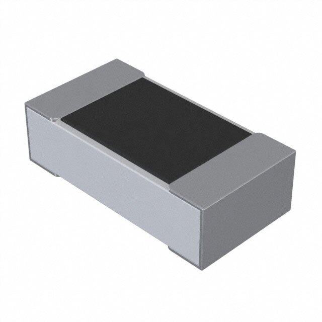
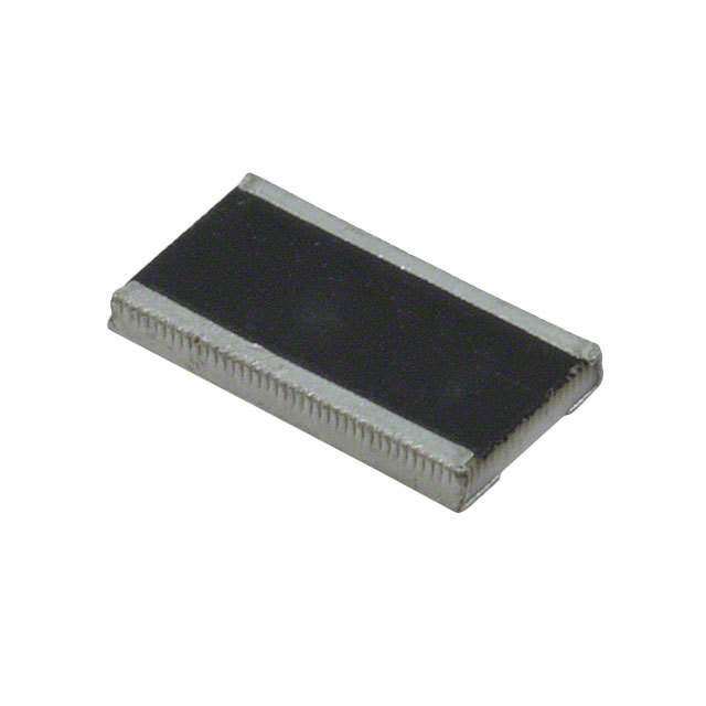
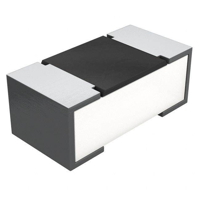
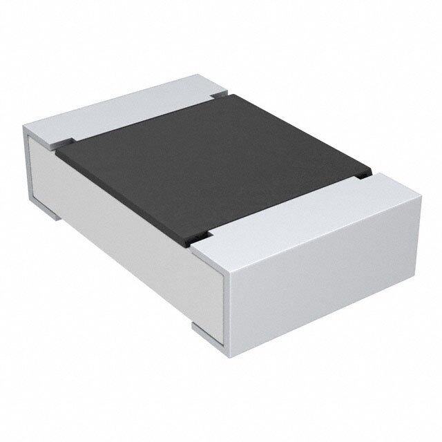
ICGOO电子元器件商城为您提供Y1627100K000T9R由Vishay Precision Group设计生产,在icgoo商城现货销售,并且可以通过原厂、代理商等渠道进行代购。 Y1627100K000T9R价格参考。Vishay Precision GroupY1627100K000T9R封装/规格:芯片电阻 - 表面安装, 100 kOhms ±0.01% 0.5W,1/2W 金属箔 芯片电阻 2010(5025 公制) 防潮,非电感 金属箔。您可以下载Y1627100K000T9R参考资料、Datasheet数据手册功能说明书,资料中有Y1627100K000T9R 详细功能的应用电路图电压和使用方法及教程。
| 参数 | 数值 |
| 产品目录 | |
| 描述 | RES 100K OHM 1/2W .01% 2010 |
| 产品分类 | |
| 品牌 | Vishay Foil Resistors (Division of Vishay Precision Group) |
| 数据手册 | |
| 产品图片 |
|
| 产品型号 | Y1627100K000T9R |
| rohs | 无铅 / 符合限制有害物质指令(RoHS)规范要求 |
| 产品系列 | VSMP |
| 产品培训模块 | http://www.digikey.cn/PTM/IndividualPTM.page?site=cn&lang=zhs&ptm=15132 |
| 产品目录绘图 |
|
| 产品目录页面 | |
| 供应商器件封装 | 2010 |
| 其它名称 | Y1627-100KDKR |
| 其它有关文件 | |
| 功率(W) | 0.5W,1/2W |
| 包装 | Digi-Reel® |
| 大小/尺寸 | 0.198" 长 x 0.097" 宽(5.03mm x 2.46mm) |
| 容差 | ±0.01% |
| 封装/外壳 | 2010(5025 公制) |
| 成分 | 金属箔 |
| 标准包装 | 1 |
| 温度系数 | ±0.2ppm/°C |
| 特性 | 防潮,非电感 |
| 电阻(Ω) | 100k |
| 端子数 | 2 |
| 高度 | 0.025"(0.64mm) |


- 商务部:美国ITC正式对集成电路等产品启动337调查
- 曝三星4nm工艺存在良率问题 高通将骁龙8 Gen1或转产台积电
- 太阳诱电将投资9.5亿元在常州建新厂生产MLCC 预计2023年完工
- 英特尔发布欧洲新工厂建设计划 深化IDM 2.0 战略
- 台积电先进制程称霸业界 有大客户加持明年业绩稳了
- 达到5530亿美元!SIA预计今年全球半导体销售额将创下新高
- 英特尔拟将自动驾驶子公司Mobileye上市 估值或超500亿美元
- 三星加码芯片和SET,合并消费电子和移动部门,撤换高东真等 CEO
- 三星电子宣布重大人事变动 还合并消费电子和移动部门
- 海关总署:前11个月进口集成电路产品价值2.52万亿元 增长14.8%


PDF Datasheet 数据手册内容提取
VVSSMMPP SSeerriieess ( 0(600630,3 0,8 00850, 152,0 162, 10560, 61, 2500160, ,2 2051102,) (Z25 F1o2il)) (Z Foil) UUllttrraa HHiigghh PPrreecciissiioonn FFooiill WWrraappaarroouunndd SSuurrffaaccee MMoouunntt CChhiipp RReessiissttoorr with TCR of ±0.05 ppm/°C and Power Coefficient of 5 ppm at Rated Power and Load Life Stability of ±0.005% (50 ppm) FEATURES • Temperature coefficient of resistance (TCR): 0.2 ppm/°C typical (–55°C to +125°C, +25°C ref.) • Resistance tolerance: to ±0.01% • Power coefficient “∆R due to self heating”: 5 ppm at rated power • Power rating: to 750 mW at +70°C (see table 3) • Load life stability: to ±0.005% at 70°C, 2000 h at rated power • Resistance range: 5 Ω to 125 kΩ (for lower or higher Top View values, please contact us) (for date code print specification please refer to table 2) • Bulk Metal Foil resistors are not restricted to standard values, we can supply specific “as required” values at no extra cost or delivery (e.g. 1K2345 vs. 1K) INTRODUCTION • Thermal stabilization time <1 s (nominal value achieved within 10 ppm of steady state value) VSMP Series is the industry’s first device to provide high • Electrostatic discharge (ESD) at least to 25 kV rated power and excellent load life stability along with extremely low TCR – all in one resistor. • Short time overload: ≤0.005% • Non inductive, non capacitive design One of the most important parameters influencing stability is the Temperature Coefficient of Resistance (TCR). • Rise time: 1 ns effectively no ringing Although the TCR of Bulk Metal® Foil is considered • Current noise: 0.010 μV /V of applied voltage RMS extremely low, this characteristic has been further (<–40 dB) refined over the years. The VSMP Series utilizes ultra • Voltage coefficient <0.1 ppm/V high precision Z Foil. The Z Foil technology provides a (resistance values above 10 kΩ) significant reduction of the resistive element’s sensitivity • Non inductive: <0.08 μH to ambient temperature variations (TCR) and to self heating when power is applied (Power Coefficient of • Non hot spot design Resistance, or PCR). Along with the inherently low PCR • Terminal finishes available: lead (Pb)-free, tin/lead alloy and TCR, Z Foil technology also provides remarkably • Matched sets are available on request improved load life stability, low noise and tight tolerances. • Screening in accordance with EEE-INST-002 and Vishay Foil Resistors’ (VFR) application engineering MIL-PRF-55342 available (see datasheet resistor department is available to advise and make models 303133 to 303138) recommendations. For non-standard technical • Quick prototype quantities available, please contact requirements and special applications, please contact foil@vpgsensors.com us using the e-mail address in the footer below. Table 1—Tolerance and TCR vs. Resistance Figure 1—Power Derating Curve Value(1) (–55°C to +125°C, +25°C Ref.) Typical TCR and er - 55 °C + 70 °C Resistance value Tolerance w100 max. Spread o P 250 Ω to 125 kΩ ±0.01% ±0.2 ±1.8 ppm/°C d 75 e 100 Ω to <250 Ω ±0.02% ±0.2 ±1.8 ppm/°C at 50 Ω to <100 Ω ±0.05% ±0.2 ±2.8 ppm/°C of R 50 25 Ω to <50 Ω ±0.1% ±0.2 ±3.8 ppm/°C nt 25 10 Ω to <25 Ω ±0.25% ±0.2 ±3.8 ppm/°C e c 5 Ω to <10 Ω ±0.5% ±0.2 ±7.8 ppm/°C er 0 P - 75 - 50 - 25 0 + 25 + 50 + 75 + 100+ 125 + 150+ 175 (1) For tighter performances and non-standard values lower than Ambient Temperature (°C) 5 Ω and above 125 kΩ, please contact application engineering using the e-mail addresses in the footer below * This datasheet provides information about parts that are RoHS-compliant and/or parts that are non-RoHS-compliant. For example, parts with lead (Pb) terminations are not RoHS compliant. Please see the information/tables in this datasheet for details. DDooccuummeenntt NNoo..:: 6633006600 For any questions, contact www.vishayfoilresistors.com RReevviissiioonn:: 2255--JJuull--22001166 foil@vpgsensors.com 1
VVSSMMPP S Seerireies (s0 6(00630, 038, 0058, 10250, 61,2 10560,6 ,1 2500160,, 22501120) (,Z 2 F5o1i2l)) (Z Foil) Figure 2—Trimming to Values Figure 3—Typical Resistance / (Conceptual Illustration) Temperature Curve Interloop TCR Values for Different Temperature Ranges capacitance reduction Current path +500 in series before trimming +400 +300 Mutual Current path after trimming +200 inductance reduction Trimming process ∆R +100 due to change removes this material R 0 idni rceucrtrioennt fcrhoamn gsihnogr tcinugrr estnrtip p aarthea (ppm)–100 0.05 ppm/°C and increasing –200 –0.1 ppm/°C 0.1 ppm/°C resistance –300 0.14 ppm/°C Foil shown in black, etched spaces in white –400 –0.16 ppm/°C 0.2 ppm/°C Note –500 To acquire a precision resistance value, the Bulk Metal® Foil –55 –25 0 +25 +60 +75 +100 +125 chip is trimmed by selectively removing built-in “shorting bars.” Ambient Temperature (°C) To increase the resistance in known increments, marked areas are cut, producing progressively smaller increases in Note resistance. This method reduces the effect of “hot spots” and The TCR values for <100 Ω are influenced by the termination improves the long-term stability of Bulk Metal Foil resistors. composition and result in deviation from this curve Table 2—Dimensions and Land Pattern in Inches (Millimeters) Top View Recommended Land Pattern Date Code2 L (Year/Week) Footprint X W G T Z D L W Thickness D Chip Size Z(1) G(1) X(1) ±0.005 (0.13) ±0.005 (0.13) Maximum ±0.005 (0.13) 0603 0.063 (1.60) 0.032 (0.81) 0.025 (0.64) 0.011 (0.28) 0.102 (2.59) 0.031 (0.78) 0.031 (0.78) 0805 0.080 (2.03) 0.050 (1.27) 0.025 (0.64) 0.015 (0.38) 0.122 (3.10) 0.028 (0.71) 0.050 (1.27) 1206 0.126 (3.20) 0.062 (1.57) 0.025 (0.64) 0.020 (0.51) 0.175 (4.45) 0.059 (1.50) 0.071 (1.80) 1506 0.150 (3.81) 0.062 (1.57) 0.025 (0.64) 0.020 (0.51) 0.199 (5.05) 0.083 (2.11) 0.071 (1.80) 2010 0.198 (5.03) 0.097 (2.46) 0.025 (0.64) 0.025 (0.64) 0.247 (6.27) 0.115 (2.92) 0.103 (2.62) 2512 0.249 (6.32) 0.127 (3.23) 0.025 (0.64) 0.032 (0.81) 0.291 (7.39) 0.150 (3.81) 0.127 (3.23) (1) Land Pattern Dimensions are per IPC-7351A (2) The date code printing applies to all resistor sizes except for 0603 Table 3—Specifications Table 4—Load Life Stability (+70°C for 2000 h) Rated Max. Working Chip Size ∆R Limits Chip Resistance Maximum Power at Voltage Size(1) Range(2) Weight ±0.005% at 50 mW +70°C (≤√P × R) 0603 ±0.01% at 100 mW 0603 100 mW 20 V 100 Ω to 5 kΩ 3 mg ±0.005% at 100 mW 0805 0805 200 mW 40 V 5 Ω to 8 kΩ 6 mg ±0.01% at 200 mW 1206 300 mW 87 V 5 Ω to 25 kΩ 11 mg ±0.005% at 150 mW 1206, 1506 ±0.01% at 300 mW 1506 300 mW 95 V 5 Ω to 30 kΩ 12 mg ±0.005% at 200 mW 2010 500 mW 187 V 5 Ω to 70 kΩ 27 mg 2010 ±0.01% at 500 mW 2512 750 mW 220 V 5 Ω to 125 kΩ 40 mg ±0.005% at 500 mW 2512 ±0.01% at 750 mW (1) For size 2018, please contact us using the e-mail address in the footer below. (2) For non-standard values please contact application engineering www.vishayfoilresistors.com For any questions, contact Document No.: 63060 2 foil@vpgsensors.com Revision: 25-Jul-2016
VSMP Series (0603, 0805, 1206, 1506, 2010, 2512) (Z Foil) Table 5—Performances MIL-PRF-55342 Performance Test or Conditions Typical ∆R Limits Characteristic E ∆R Limits ∆R Limits(1) Thermal Shock, 100 × (–65°C to +150°C) ±0.1% ±0.005% (50 ppm) ±0.01% (100 ppm) Low Temperature Operation, –65°C, 45 min at P ±0.1% ±0.005% (50 ppm) ±0.01% (100 ppm) nom Short Time Overload, 6.25 × Rated Power, 5 s ±0.1% ±0.005% (50 ppm) ±0.01% (100 ppm) High Temperature Exposure, +150°C, 100 h ±0.1% ±0.01% (100 ppm) ±0.02% (200 ppm) Resistance to Soldering Heat ±0.2% ±0.005% (50 ppm) ±0.01% (100 ppm) Moisture Resistance ±0.2% ±0.005% (50 ppm) ±0.02% (200 ppm) Load Life Stability +70°C for 2000 h at Rated Power ±0.5% ±0.005% (50 ppm) ±0.01% (100 ppm) (1) As shown +0.01 Ω to allow for measurement errors at low values Figure 4—Recommended Mounting 1. IR and vapor phase reflow are recommended. 2. Avoid the use of cleaning agents that attack epoxy resins, which form part of the resistor construction. * 3. Vacuum pick up is recommended for handling. 4. If the use of a soldering iron becomes necessary, precautionary measures should be taken to avoid any possible damage/overheating of the resistor. * Recommendation: The solder fillet profile should be such as to avoid running over the top metallization. Figure 5—VSMP0603 100 Cycle Thermal Figure 6—Load Life Test for Shock –65°C to 150°C, 10 Units Each Value 10,000 hrs @0.3 W, +70°C; Vsmp 1206, N=40 100 500 80 400 60 300 m) p 40 p 200 ∆R/R ( 20 100 0 - 20 (ppRm ) 0 0 1000 2000 3000 4000 5000 6000 7000 8000 9000 10000 110KR -100 - 40 12K VSMP0603 VSMP0603 VSMP0603 100R 1K 5K -200 -300 -400 -500 Time (hrs) Document No.: 63060 For any questions, contact www.vishayfoilresistors.com Revision: 25-Jul-2016 foil@vpgsensors.com 3
VVSSMMPP S Seerireies (s0 6(00630, 038, 0058, 10250, 61,2 10560,6 ,1 2500160,, 22501120) (,Z 2 F5o1i2l)) (Z Foil) PULSE TEST Latent Damage – occurs when the ESD event causes moderate damage to the device, which is not noticeable, Test Description as the device appears to be functioning correctly. All parts are baked at +125°C for 1 hour and allowed However, the load life of the device has been dramatically to cool at room temperature for 1 hour, prior to testing. reduced, and further degradation caused by operating By using an electrolytic 0.01 μF capacitor charged to stresses may cause the device to fail during service. 1200 VDC, a single pulse was performed on 30 units of Latent damage is the source for greatest concern, since it 1206, 10 kΩ of Surface Mount Bulk Metal® Foil resistor and is very difficult to detect by re-measurement or by visual Pulse TesTth in Film resistor. The units were allowed time to cool down, inspection, because damage may have occurred under after which the resistance measurements were taken and the external coating. Test Description displayed in ppm deviation from the initial reading. All parts baked at +125ْC for 1 hr and allowed to cool at room temperature for 1 hr, prior to testing. By using an electrolytic 0.01ΩμF caΩpacitor chaΩrged to 1000 VDC, a single pulse was Test Description performed on 20 units of 1206: 100 , 1K and 10K of Surface Mount Vishay Foil Resistor and Test Results Thin Film Resistor. The unit was allowed time to cool down, after which the resistance By using an electrolytic 500 pF capacitor charged up to measurement was taken and displayed in ppm deviation from the initial reading. 4500 V, pulses were performed on 10 units of 1206, Figure 7—Pulse Test Description 10 kΩ of three different Surface Mount Chip Resistors technologies, with an initial voltage spike of 2500 V (Figure 10). The units were allowed time to cool down, after which the resistance measurements were taken and displayed in ppm deviation from the initial readings. Readings were then taken in 500 V increments up to 4500 V. 1200 0.01µF Rx VDC Figure 9—ESD Test Description 2500 V to 4500 V 1 MΩ Test Results Figure 8—Pulse Test ResuAlvtesra gaet D1e2via0ti0on V (%D)C* Value Voltage τ= RC Foil Thin Film 114000000R 1μsec Open 12010K00 1000VDC 10 μsec <0.001 >35 500 pF 10K 100 μsec >0.008 100000 Thin Film m) 80000 Bulk Metal® Foil ∆R (pp 60000 VSaliuzee:: 11200K6 Rx 40000 n = 30 20000 0 0 5 10 15 20 25 30 -20000 Resistor # DMM Note: Average of 30 units yielded deviation of 30,723 ppm of the Thin Film vs. –14 ppm for the Bulk Metal® Foil * Note Average of 30 units yielded deviation of 30,723 ppm of the Thin Film vs. –14 ppm for the Bulk Metal® Foil Table 6—ESD Test Results ELECTROSTATIC DISCHARGE (ESD) (Average of 10 Units) ESD can be categorized into three types of damages: ∆R Parametric Failure – occurs when the ESD event alters Thick Film Thin Film Bulk Metal Foil one or more device parameters (resistance in the case of 2500 V –2.7% 97% <0.005% resistors), causing it to shift from its required tolerance. This failure does not directly pertain to functionality; thus 3000 V –4.2% 366% <0.005% a parametric failure may be present while the device is 3500 V –6.2% Open <0.005% still functional. 4000 V –7.4% Open <0.005% Catastrophic Damage – occurs when the ESD event 4500 V –8.6% Open <0.005% causes the device to immediately stop functioning. This may occur after one or a number of ESD events with diverse causes, such as human body discharge or the mere presence of an electrostatic field. www.vishayfoilresistors.com For any questions, contact Document No.: 63060 4 foil@vpgsensors.com Revision: 25-Jul-2016
VSMP Series (0603, 0805, 1206, 1506, 2010, 2512) (Z Foil) Table 7—Global Part Number Information(1) NEW GLOBAL PART NUMBER: Y162612K7560T9R (preferred part number format) DENOTES PRECISION VALUE CHARACTERISTICS Y R = Ω 0 = standard K = kΩ 9 = lead (Pb)-free 1 to 999 = custom Y 1 6 2 61 2 K 7 5 6 0 T 9 R PRODUCT CODE RESISTANCE TOLERANCE PACKAGING 1636 = VSMP0603 T = ±0.01% R = tape and reel 1624 = VSMP0805 Q= ±0.02% W= waffle pack 1625 = VSMP1206 A= ±0.05% 1626 = VSMP1506 B= ±0.10% 1627 = VSMP2010 C= ±0.25% 1637 = VSMP2018(2) D= ±0.5% 1628 = VSMP2512 F = ±1.0% FOR EXAMPLE: ABOVE GLOBAL ORDER Y1626 12K7560 T 9 R: TYPE: VSMP1506 VALUES: 12.7560 kΩ ABSOLUTE TOLERANCE: 0.01% TERMINATION: lead (Pb)-free PACKAGING: tape and reel HISTORICAL PART NUMBER: VSMP1506 12K756 TCR0.2 T S T (will continue to be used) VSMP1506 12K756 TCR0.2 T S T RESISTANCE TCR MODEL TOLERANCE TERMINATION PACKAGING VALUE CHARACTERISTICS VSMP0603 12.756 kΩ T = ±0.01% S = lead (Pb)-free T = tape and reel VSMP0805 Q= ±0.02% B= tin/lead W= waffle pack VSMP1206 A= ±0.05% VSMP1506 B= ±0.10% VSMP2010 C= ±0.25% VSMP2018(2) D= ±0.5% VSMP2512 F = ±1.0% (1) For non-standard requests, please contact application engineering. (2) For size 2018, please contact us PRECISION CENTER Precision centers are located around the world to provide in any ohmic value (no MOQ) local, short run, quick delivery of Bulk Metal® Foil resistors. Since Bulk Metal Foil is not restricted to standard values and each resistor is trimmed to the precise value ordered, the unique chain of Precision Centers brings these precise values as close as possible to the circuit designers in the shortest time possible. For your local Precision Center please click here. Document No.: 63060 For any questions, contact www.vishayfoilresistors.com Revision: 25-Jul-2016 foil@vpgsensors.com 5
LLeeggaall DDiissccllaaiimmeerr NNoottiiccee Vishay Precision Group, Inc. DDiissccllaaiimmeerr ALL PRODUCTS, PRODUCT SPECIFICATIONS AND DATA ARE SUBJECT TO CHANGE WITHOUT NOTICE. Vishay Precision Group, Inc., its affiliates, agents, and employees, and all persons acting on its or their behalf (collectively, “VPG”), disclaim any and all liability for any errors, inaccuracies or incompleteness contained herein or in any other disclosure relating to any product. The product specifications do not expand or otherwise modify VPG’s terms and conditions of purchase, including but not limited to, the warranty expressed therein. VPG makes no warranty, representation or guarantee other than as set forth in the terms and conditions of purchase. To the maximum extent permitted by applicable law, VPG disclaims (i) any and all liability arising out of the application or use of any product, (ii) any and all liability, including without limitation special, consequential or incidental damages, and (iii) any and all implied warranties, including warranties of fitness for particular purpose, non-infringement and merchantability. Information provided in datasheets and/or specifications may vary from actual results in different applications and performance may vary over time. Statements regarding the suitability of products for certain types of applications are based on VPG’s knowledge of typical requirements that are often placed on VPG products. It is the customer’s responsibility to validate that a particular product with the properties described in the product specification is suitable for use in a particular application. You should ensure you have the current version of the relevant information by contacting VPG prior to performing installation or use of the product, such as on our website at vpgsensors.com. No license, express, implied, or otherwise, to any intellectual property rights is granted by this document, or by any conduct of VPG. The products shown herein are not designed for use in life-saving or life-sustaining applications unless otherwise expressly indicated. Customers using or selling VPG products not expressly indicated for use in such applications do so entirely at their own risk and agree to fully indemnify VPG for any damages arising or resulting from such use or sale. Please contact authorized VPG personnel to obtain written terms and conditions regarding products designed for such applications. Product names and markings noted herein may be trademarks of their respective owners. Copyright Vishay Precision Group, Inc., 2014. All rights reserved. Document No.: 63999 www.vpgsensors.com Revision: 15-Jul-2014 1