ICGOO在线商城 > 连接器,互连器件 > 矩形连接器 - 配件 > XG5S-2001
 Datasheet下载
- 型号: XG5S-2001
- 制造商: Omron Electronics LLC
- 库位|库存: xxxx|xxxx
- 要求:
| 数量阶梯 | 香港交货 | 国内含税 |
| +xxxx | $xxxx | ¥xxxx |
查看当月历史价格
查看今年历史价格
XG5S-2001产品简介:
ICGOO电子元器件商城为您提供XG5S-2001由Omron Electronics LLC设计生产,在icgoo商城现货销售,并且可以通过原厂、代理商等渠道进行代购。 XG5S-2001价格参考¥1.88-¥1.88。Omron Electronics LLCXG5S-2001封装/规格:矩形连接器 - 配件, 。您可以下载XG5S-2001参考资料、Datasheet数据手册功能说明书,资料中有XG5S-2001 详细功能的应用电路图电压和使用方法及教程。
| 参数 | 数值 |
| 产品目录 | |
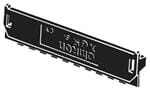
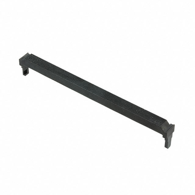
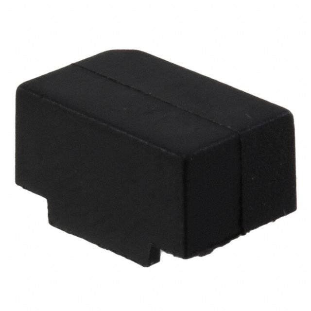
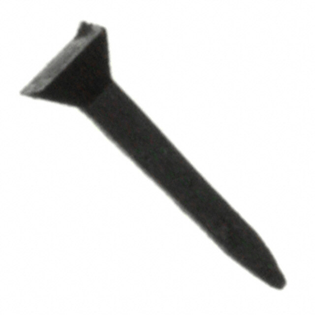
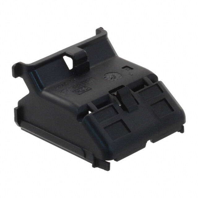
| 描述 | CONN SEMI-COVER 20POS FOR XG5M集管和线壳 Semi-Cover for XG5M Series 20P |
| 产品分类 | |
| 品牌 | Omron Electronics |
| 产品手册 | |
| 产品图片 |
|
| rohs | 符合RoHS无铅 / 符合限制有害物质指令(RoHS)规范要求 |
| 产品系列 | Omron Electronics XG5S-2001XG5 |
| mouser_ship_limit | 该产品可能需要其他文档才能发货到中国。 |
| 数据手册 | |
| 产品型号 | XG5S-2001 |
| 产品培训模块 | http://www.digikey.cn/PTM/IndividualPTM.page?site=cn&lang=zhs&ptm=24856http://www.digikey.cn/PTM/IndividualPTM.page?site=cn&lang=zhs&ptm=25458 |
| 产品目录页面 | |
| 产品种类 | 集管和线壳 |
| 产品类型 | |
| 位置数量 | 20 |
| 其它名称 | OR944 |
| 其它有关文件 | |
| 可燃性等级 | UL 94 V-0 |
| 商标 | Omron Electronics |
| 外壳材料 | Polyamide (PA) |
| 安装风格 | - |
| 工厂包装数量 | 500 |
| 排数 | 1 |
| 标准包装 | 1,000 |
| 特性 | - |
| 端接柱长度 | - |
| 端接类型 | - |
| 类型 | - |
| 系列 | XG5 |
| 胶壳接口类型 | - |
| 节距 | - |
| 行距 | - |
| 触点材料 | - |
| 触点电镀 | - |
| 触点类型 | - |
| 配件类型 | 帽盖(盖) |
| 配合柱长度 | - |
| 配套使用产品/相关产品 | XG5 系列 |
| 配用 | /product-detail/zh/XG5M-4035-N/XG5M-4035-N-ND/2627559/product-detail/zh/XG5M-4032-N/OR939-ND/1787250 |
| 针脚数 | 20 |
| 附件类型 | Semi-Cover |
| 零件号别名 | 1756295 385323 |


- 商务部:美国ITC正式对集成电路等产品启动337调查
- 曝三星4nm工艺存在良率问题 高通将骁龙8 Gen1或转产台积电
- 太阳诱电将投资9.5亿元在常州建新厂生产MLCC 预计2023年完工
- 英特尔发布欧洲新工厂建设计划 深化IDM 2.0 战略
- 台积电先进制程称霸业界 有大客户加持明年业绩稳了
- 达到5530亿美元!SIA预计今年全球半导体销售额将创下新高
- 英特尔拟将自动驾驶子公司Mobileye上市 估值或超500亿美元
- 三星加码芯片和SET,合并消费电子和移动部门,撤换高东真等 CEO
- 三星电子宣布重大人事变动 还合并消费电子和移动部门
- 海关总署:前11个月进口集成电路产品价值2.52万亿元 增长14.8%

.jpg)
.jpg)
PDF Datasheet 数据手册内容提取
IDC Connectors for Discrete Wires XG5 Trouble-free discrete-wire termination * with IDC Sockets that accommodate MIL Plugs. ■ Two-slot, IDC construction and insulation barrel offer high reliability and large-current (3A) discrete wiring capability. ■ Adaptable to a variety of covers for space-saving and discrete wire termination. ■ By using the simple, unique lock-lever system, these Connectors can be locked to either the XG8B/XG8W Unshrouded Plugs (with right-angle terminals) or XG4C Box-type Plugs. ■ Conforms to UL standards (file no. E103202). (Except for XG5S models) RoHS Compliant * Excluding XG5S ■Terminology • Insulation barrel (cid:129) Insulation height Wire Refers to the part of a Refers to the height of the contact that crimps the insulation barrel after insulating sheath of a crimping or IDC pressing. Insulation wire. (cid:129) Lance height Refers to the lance-like projections arranged on a contact to secure it in the housing. Insulation barrel Lance 2-slot IDC pressing (cid:129) U-slot Mating end Refers to the part where the wire and the contact connect to each other. It is called a U-slot because of its shape. ■Construction Solderless Contact Cover (Semi-cover or Hood Cover) Semi-cover shown here. Socket (with polarizing guide) Wire can be connected without stripping cable insulation. Lance Insulation barrel IDC contacts Polarizing guide Two-slot connection ■Ratings and Characteristics ■Current and Temperature Characteristics Use the temperature data shown below as a reference for selecting current values and wires. Rated current 1 A (AWG28), 2 A (AWG26), Rated voltage 33 0A0 (VAAWCG24) °ure (C) °ure (C) Flow rate = (n(too.t aolf ncoo.n otaf cctosn utascetds)) × 100% Contact resistance m20A m mΩa xm.)ax. (at 20mV, 100 mperat UULL11006017 AAWWGG2246 ((XXGG55MM--22003325--NN)) 20 wires mperat UULL11006017 AAWWGG2246 IDniseulelacttiroicn sretrseinsgtathnce 156,050000 V0V ADMCCΩ )f omr i1n .m (aint (leakage Rise in te Temp. rise limit 2w0ir es 10 wires Rise in te Temp. rise limit current: 1 mA max.) 10 wires 2 wires Total insertion force 1.96 N max. per contact 2w ires Removal force 0.29 N min. (with test gauge, 0.64 x 0.64 mm) Insertion durability 50 times Ambient operating −55 to 85°C (with no icing at temperature low temperature) Current flow (A) Current flow (A) 1
■Materials and Finish ■Applicable Wires and Contact Sizes Housing Fiber-glass reinforced PBT resin (UL94 Size #1 AWG24 (For UL1061) Insulation outside diame- V-0)/black Size #2 AWG28 or AWG26 ter: 1.1 to 1.3 mm Contacts Mating end Phosphor-bronze/nickel base, 0.15-μm (For UL1007) Core structure: 7 strands gold plating or more Terminals Phosphor-bronze/nickel base, 2.0-μm solder plating Note: The contact numbers are marked on the contact insulation Cover Fiber-glass reinforced polyamide resin barrels. (UL94 V-0)/black Cable tie Polyamide resin (UL94 V-0)/natural ■Configuration Assembly Socket Wire Connections Cover Assembled unit Discrete wires Semi-cover Double rows with polarity Double-row guide Assembled (lockable) Hood Cover IDC Tool Double rows Vertical with polarity guide (lockable) Double rows Horizontal with polarity Simple IDC Tool guide (lockable) ■Applicable Plugs XG4A XG4A XG4A Flat Cable Plugs without Flat Cable MIL Plugs with Flat Cable Double-row Lock Lever (Lock Levers Long Locks Plugs mounted later) XG4E XG4C XG8W/XG8B IDC Flat Cable Plugs Flat Cable Box-type Plugs Double-row Original Plugs Long Locks Note: 1. Plug dimensions are listed on the Plug's page. 2. When using the XG4A or XG4C, the number of XG4A or XG4C's slots must be the same as the number of XG5M-N polarity guides. 2 IDC Connectors for Discrete Wires XG5
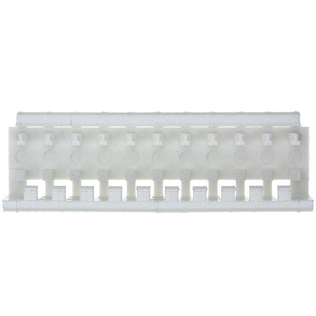
XG5M-N Double-row Sockets ■ Dimensions (Unit: mm) Models with no polarizing guide XG5M-1031-N (size #1) Dimensions Size no. XG5M-1034-N (size #2) No. of Dimensions (mm) Models with polarizing guide contacts A B XG5M-@@32-N (size #1) 10 17.3 10.16 XG5M-@@33-N (size #1) 14 22.3 15.24 XG5M-@@35-N (size #2) XG5M-@@36-N (size #2) 16 24.9 17.78 Polarizing guide 20 30.0 22.86 26 37.6 30.48 30 42.7 35.56 34 47.7 40.64 40 55.4 48.26 50 68.1 60.96 60 80.8 73.66 64 85.8 78.74 ■ Ordering Information Appearance No. of No. of Size #1 (See note 1.) Size #2 (See note 2.) contacts polarizing guide 10 0 XG5M-1031-N XG5M-1034-N 1 XG5M-1032-N XG5M-1035-N 14 1 XG5M-1432-N XG5M-1435-N 16 1 XG5M-1632-N XG5M-1635-N 20 1 XG5M-2032-N XG5M-2035-N 26 1 XG5M-2632-N XG5M-2635-N 30 1 XG5M-3032-N XG5M-3035-N 34 1 XG5M-3432-N XG5M-3435-N 40 1 XG5M-4032-N XG5M-4035-N 50 1 XG5M-5032-N XG5M-5035-N 2 XG5M-5033-N XG5M-5036-N 60 1 XG5M-6032-N XG5M-6035-N 2 XG5M-6033-N XG5M-6036-N 64 1 XG5M-6432-N XG5M-6435-N 2 XG5M-6433-N XG5M-6436-N Note:1. The 10-contact XG5M-1031-N and XG5M-1034-N have no polarizing guides. The distance between slots is 22.86 mm for the two guides on 50, 60, and 64-contact Connectors. 2. See the previous page for Plug information. 3. Applicable wire is AWG24 (UL1061) for size #1. 4. Applicable wire is AWG28 to AWG26 (UL1007) for size #2. For details, see the previous page. IDC Connectors for Discrete Wires XG5 3
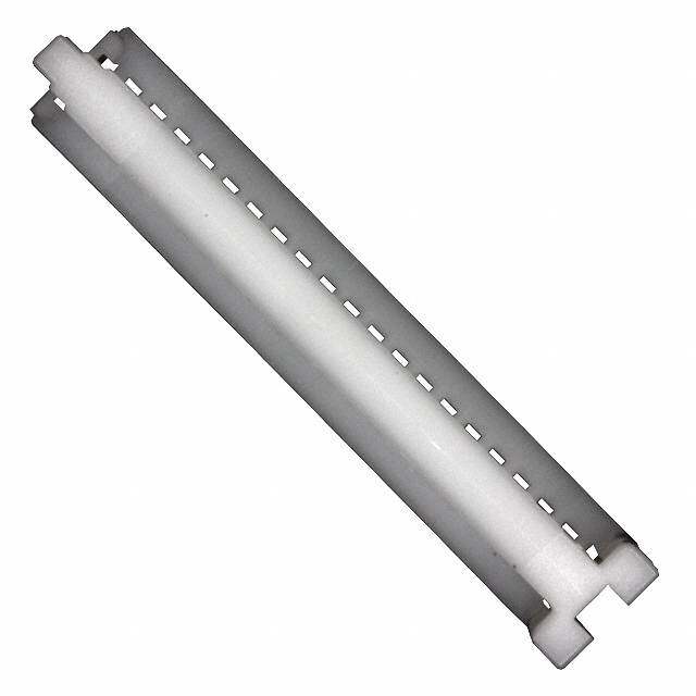
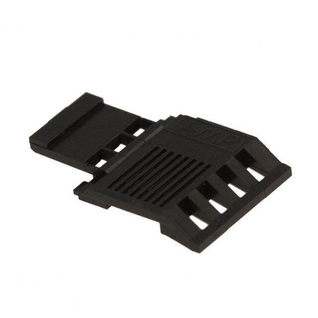
XG5S Semi-covers ■ Dimensions (Unit: mm) XG5S-@@01 Dimensions No. of Dimensions (mm) contacts A 5 17.3 7 22.3 8 24.9 10 30.0 13 37.6 15 42.7 17 47.7 20 55.4 25 68.1 30 80.8 32 85.8 ■ Ordering Information No. of Model Applicable Connector contacts 5 XG5S-0501 XG5M-103@-N 7 XG5S-0701 XG5M-143@-N 8 XG5S-0801 XG5M-163@-N Semi-covers XG5S-@@01 10 XG5S-1001 XG5M-203@-N 13 XG5S-1301 XG5M-263@-N 15 XG5S-1501 XG5M-303@-N Double-row Sockets 17 XG5S-1701 XG5M-343@-N XG5M-@@3@-N 20 XG5S-2001 XG5M-403@-N 25 XG5S-2501 XG5M-503@-N Note: One Semi-cover is used per row. 30 XG5S-3001 XG5M-603@-N Each XG5M Connector requires two semi-covers. 32 XG5S-3201 XG5M-643@-N ■ Assembled Dimensions (Socket with Semi-cover) Dimensions Original Plug + Semi- MIL Plug + Semi-cover cover + Lock Lever No. of Dimensions (mm) contacts A B 10 17.3 32.0 14 22.3 37.1 16 24.9 39.6 20 30.0 44.7 26 37.6 52.3 30 42.7 57.4 34 47.7 62.5 40 55.4 70.1 50 68.1 82.8 60 80.8 95.5 64 85.8 100.6 4 IDC Connectors for Discrete Wires XG5
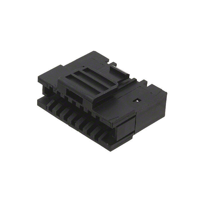
XG5S Hood Covers ■ Dimensions (Unit: mm) Vertical/XG5S-@@12 (Left and right halves) Dimensions No. of Dimensions (mm) contacts A B C 20 30.0 23.8 8.8 26 37.6 31.4 11.4 30 42.7 36.5 15.1 Horizontal/XG5S-@@22 (Left and right halves) Dimensions No. of Dimensions (mm) contacts A B C D 34 47.7 38.7 32.0 14.6 40 55.4 40.7 34.0 16.6 50 68.1 44.1 39.4 20.0 60 80.8 47.4 42.8 23.4 ■ Ordering Information Appearance Vertical Horizontal No. of contacts Model (See note.) Model (See note.) (double rows) 20 XG5S-2012 --- 26 XG5S-2612 --- 30 XG5S-3012 --- 34 --- XG5S-3422 40 --- XG5S-4022 50 --- XG5S-5022 60 --- XG5S-6022 Note:Includes cable tie. IDC Connectors for Discrete Wires XG5 5
■ Assembled Dimensions (Socket and Hood Cover) (Unit: mm) Vertical Hood Cover Assembled Unit MIL Plug + Vertical Hood Cover Dimensions No. of Dimensions (mm) contacts A B 20 30.0 44.7 26 37.6 52.3 30 42.7 57.4 Horizontal Hood Cover Assembled Unit MIL Plug + Horizontal Hood Cover Dimensions No. of Dimensions (mm) contacts A B C D E F 34 47.7 39.0 45.7 62.5 46.4 53.1 40 55.4 41.0 47.7 70.1 48.4 55.1 50 68.1 46.4 51.1 82.8 53.8 58.5 60 80.8 49.8 54.4 95.5 57.2 61.8 6 IDC Connectors for Discrete Wires XG5
■ XG5 Accessories (Sold Separately) Lock Levers Lock Levers II XG5Z-0002 XG4Z-0002 Use to lock Unshrouded Plugs (XG8B and XG8W, with right- Use to lock XG4C Box-type Plugs. angle terminals). Material: Polyamide resin Material: Polyamide resin (UL94 V-2)/natural (UL94 V-2)/natural Mounting the Lock Lever For Sockets with polarity guides, mount the Model Lock Lever to the tab to lock the Socket to the XG5Z-0002 Unshrouded Plug as shown in the diagram on XG4Z-0002 the right. Note:When you order the above products, order them in multi- ples of the minimum ordering quantity (pieces). Spare Contacts Size no. Model XG5W-0031-N (Size #1) XG5W-0034-N (Size #2) XG5W-0031-N XG5W-0034-N Note:1. When you order the above products, order them in multi- ples of the minimum ordering quantity (pieces). 2. These Contacts can be used as replacements if a wrong connection is made. 3. The applicable wire for size No. 1 is AWG24 (UL1061). The applicable wire for size No. 2 is AWG28 to AWG26 (UL1007). See page2 for details. IDC Connectors for Discrete Wires XG5 7
■ ■ XG5 IDC Tools Tools Simple IDC Tool Simple Wire IDC Tool Set XY2B-7006 XY2B-2104-N Model XY2B-7006 This tool is a compact, light-weight model, ideal for use in the laboratory or for mainte- nance. Model Specifications XY2B-2104-N Applicable con- XG5M-N This Wire IDC Tool Set is designed for XG5 nector Discrete-wire Connectors. Applicable wire AWG24 to AWG28 (with an insulation Specifications outer diameter of 1.1 to 1.3 mm) Stroke 13 mm Dimensions 25 (W) × 100 (D) × Motor speed 83/100 rpm (50/60 Hz) 80 (H) mm Feed pitch 2.54 mm Weight Approx. 180 g Operation Foot switch ■Tools for the XG5 Weight Approx. 6 kg Rated voltage 0.5 A, 100 VAC (50/60Hz) Contact Removal Tool Fuse 1 A XY2E-0001 Dimensions 120 (W) × 225 (D) × 225 (H) mm Lance Holding Part Note:For function and operation details, see the user’s manual for the Pres- sure Welder provided separately. Applicable Connectors and Wires Model Applicable Con- Size No. Applicable wires XY2E-0001 nector UL file Size Cross-sec- Covering Used to remove from the housing, contacts No. [No. of wires/ tional area diameter which are wrong. diameter (mm)] (mm2) (mm) Replacing Contacts XG5M-@@31-N No. 1 UL1061 AWG24 [7/0.203] 0.21 1.1 XG5M-@@32-N Use only this tool to remove incorrect IDC XG5M-@@33-N contacts. XG5M-@@34-N No. 2 UL1007 AWG26 [7/0.16] 0.13 1.3 1. Remove the cover. XG5M-@@35-N AWG28 [7/0.127] 0.09 1.2 2. Insert the tool into the housing lance holes XG5M-@@36-N and push the lance into the housing. Note:Use only wires specified in the table above. 3. Pull out the contact while holding the lance down. 4. Insert a new contact. XY2E-0001 Lance hole Housing 8 IDC Connectors for Discrete Wires XG5
■ Precautions Correct Use Mounting the Hood Cover XG5M-N Double-row Socket Contact Numbers Vertical Hood Cover IDC Connectors •For best results, use only the XG5 IDC Tool. (cid:129)Contact your OMRON representative for details on the XG5 IDC Tool. (cid:129)Check the Contact size (No. 1 or No 2) and wire size before connecting. (cid:129)OMRON has a IDC Tool Reference Man- Triangular mark Contact Polarizing guide ual. Contact your OMRON representative numbers to request a copy. Mounting the Cover (cid:129)The cover is used to protect the connec- tion position and prevent shorting out. XG4M Contact Numbers Mounting the Semi-cover (cid:129)See the above diagram. 1. Insert the claws of part A of the Hood Slot Cover into the slots. 2. Insert claws B on the Hood cover into part C on the other part of the Hood Cover. 3. Wrap the wires with a cable tie. Triangular mark Not marked on connector. Semi-cover Cable tie Claw (cid:129)See the above diagram. 1. Insert part A of the Semi-cover into part (cid:129)The Contact numbers on the Double-row B of the Socket. Assembled Socket match the numbers on 2. Push the claws on both sides of the the XG4M Flat Cable MIL Socket. (See Semi-cover onto the Socket. the above diagrams.) 3. Make sure the claws are firmly inserted (cid:129)When making IDC connections on the in the slots. Double-row Assembled Connector, use the polarity guide to distinguish the front 4. To protect the wires, use cable ties to and back. (Note: The 10-contact Connec- bind wires that may be subject to ten- Horizontal Hood Cover tor does not have a guide.) sion even when a Semi-cover is used. (cid:129)Follow the mounting procedure for the Applicable Plugs vertical cover. (cid:129)The left and right parts of the cover are (cid:129)XG4A, XG4C and XG8 are recom- different. Assemble carefully. mended. (cid:129)XG4C and XG8 Plugs do not have locks. To prevent accidental removal, use a Lock Lever (XG4Z-0002, XG5Z-0002). (Lock Levers cannot be used with XG8W Straight Terminal Connectors.) (cid:129)When mounting the XG8 Original Plug (with right-angle terminals) to a circuit board, be sure that the cover is positioned off the board as shown below. Cover Original Plug Board XG5 7 mm max. Edge IDC Connectors for Discrete Wires XG5 9
(cid:129) Application examples provided in this document are for reference only. In actual applications, confirm equipment functions and safety before using the product. (cid:129) Consult your OMRON representative before using the product under conditions which are not described in the manual or applying the product to nuclear control systems, railroad systems, aviation systems, vehicles, combustion systems, medical equipment, amusement machines, safety equipment, and other systems or equipment that may have a serious influence on lives and property if used improperly. Make sure that the ratings and performance characteristics of the product provide a margin of safety for the system or equipment, and be sure to provide the system or equipment with double safety mechanisms. Note: Do not use this document to operate the Unit. OMRON Corporation Electronic and Mechanical Components Company Contact: www.omron.com/ecb Cat. No. G042-E1-04 0816(0412)(O)
Mouser Electronics Authorized Distributor Click to View Pricing, Inventory, Delivery & Lifecycle Information: O mron: XG5S-3001 XG5M-3432-N XG5S-0501 XG5S-1701 XG5M-1035-N XG5M-1432-N XG5M-1435-N XG5M-1635-N XG5M-2032-N XG5M-2035-N XG5S-0801 XG5S-1001 XG5S-1301 XG5S-2001 XG5S-2012 XG5M-2632-N XG5S- 0701 XG5S-1501 XG5S-2501 XG5S-4022 XG5M-3435-N XG5M-4035-N XG5S-2612 XG5S-3012 XG5S-3201 XG5S-3422