ICGOO在线商城 > 电感器,线圈,扼流圈 > 延迟线 > XDL15-2-020S
- 型号: XDL15-2-020S
- 制造商: Anaren Microwave
- 库位|库存: xxxx|xxxx
- 要求:
| 数量阶梯 | 香港交货 | 国内含税 |
| +xxxx | $xxxx | ¥xxxx |
查看当月历史价格
查看今年历史价格
XDL15-2-020S产品简介:
ICGOO电子元器件商城为您提供XDL15-2-020S由Anaren Microwave设计生产,在icgoo商城现货销售,并且可以通过原厂、代理商等渠道进行代购。 XDL15-2-020S价格参考¥45.35-¥45.35。Anaren MicrowaveXDL15-2-020S封装/规格:延迟线, 2.12ns ±0.28nS Inductor Delay Line 2-SMD。您可以下载XDL15-2-020S参考资料、Datasheet数据手册功能说明书,资料中有XDL15-2-020S 详细功能的应用电路图电压和使用方法及教程。
| 参数 | 数值 |
| 产品目录 | |
| DC电阻(DCR) | - |
| 描述 | IND DELAY LINE 2.0NS SMD |
| 产品分类 | |
| 品牌 | Anaren |
| 数据手册 | |
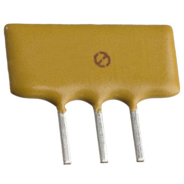
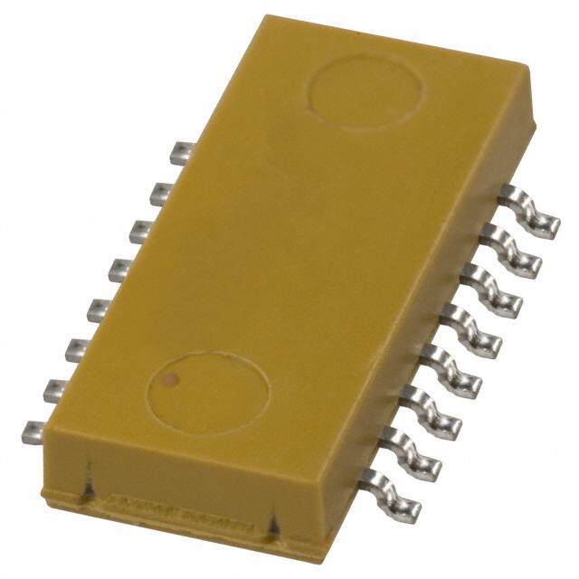
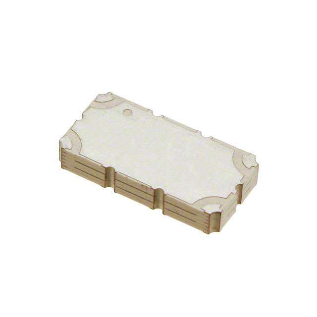
| 产品图片 |
|
| 产品型号 | XDL15-2-020S |
| rohs | 无铅 / 符合限制有害物质指令(RoHS)规范要求 |
| RoHS指令信息 | |
| 产品系列 | Xinger® |
| 其它名称 | 1173-1124-6 |
| 包装 | Digi-Reel® |
| 安装类型 | 表面贴装 |
| 容差 | - |
| 封装/外壳 | 2-SMD |
| 工作温度 | - |
| 延迟时间 | 2.0ns |
| 标准包装 | 1 |
| 电流 | - |
| 阻抗 | - |


- 商务部:美国ITC正式对集成电路等产品启动337调查
- 曝三星4nm工艺存在良率问题 高通将骁龙8 Gen1或转产台积电
- 太阳诱电将投资9.5亿元在常州建新厂生产MLCC 预计2023年完工
- 英特尔发布欧洲新工厂建设计划 深化IDM 2.0 战略
- 台积电先进制程称霸业界 有大客户加持明年业绩稳了
- 达到5530亿美元!SIA预计今年全球半导体销售额将创下新高
- 英特尔拟将自动驾驶子公司Mobileye上市 估值或超500亿美元
- 三星加码芯片和SET,合并消费电子和移动部门,撤换高东真等 CEO
- 三星电子宣布重大人事变动 还合并消费电子和移动部门
- 海关总署:前11个月进口集成电路产品价值2.52万亿元 增长14.8%


PDF Datasheet 数据手册内容提取
Model XDL15-2-020S Rev H Delay Line DESCRIPTION The XDL15-2-020S can be used in amplifier linearization applications from 112 – 2700Mhz. Small form factor of XDL15-2-020S is ideal for cascading to obtain longer delay. The Xinger® delay lines are a low cost, high quality alternative to the traditional coaxial and filter solutions presently available. Parts have been subjected to rigorous qualification testing and units are 100% tested. Produced with 6 of 6 RoHS compliant tin immersion finish. ELECTRICAL SPECIFICATIONS* Features: Return Insertion Production Friendly Frequency Loss Loss Group Amplitude Operating Power Delay Flatness Temp. Handling Consistent Delay (MHz) (dB) (dB/ns) (nS) (dB max ºC Watts Stable Over Temperature (min) (max) per 50Mhz ) Surface Mountable 112 -168 -20 -0.26 1.93 ± 0.08 0.10 -55 to +85 Available in Tape & Reel 1 Non-Lead Solder Paste 300 -2000 -17 -0.90 2.01 ± 0.17 0.10 -55 to +85 1 Compatible Lead Free 1 100% Tested 2000-2700 -14 -1.10 2.20 ± 0.20 0.10 -55 to +85 MSL1 * Specification based on performance of unit properly installed on Anaren Test Board 66111-0001. * Specifications subject to change without notice. Refer to parameter definitions for details. Mechanical Outline USA/Canada: (315) 432-8909 Available on Tape and Reel For Pick and Toll Free: (800) 544-2414 Place Manufacturing. Europe: +44 2392-232392
Model XDL15-2-020S Rev H PIN CONFIGURATION Pin 1 Pin 2 Pin 3 Pin 4 DNC- Do not connect, DNC- Do not connect, Input Output Do not ground Do not ground DNC- Do not connect, DNC- Do not connect, Output Input Do not ground Do not ground TYPICAL PERFORMANCE: 100 MHz to 3000 MHz Return Loss 2 XDL15-2-020S (OVERTEMP) Insertion Loss per ns XDL15-2-020S (OVERTEMP) 0 0 -55ºC -55ºC 25ºC 25ºC 95ºC 95ºC -10 ns) B/ -0.5 d s 2(dB) -20 per ns ( urn Los -30 on loss Ret erti -1 ns I -40 -1.5 100 400 700 1000 1300 1600 1900 2200 2500 2800 -50 100 400 700 1000 1300 1600 1900 2200 2500 2800 Frequency (MHz) Frequency (MHz) Return Loss 1 XDL15-2-020S (OVERTEMP) Group DealyXDL15-2-020S (OVERTEMP) 0 3 -55ºC -55ºC 25ºC 25ºC 95ºC 95ºC -10 2.5 Loss 1(dB) -20 Delay(ns) 2 Return -30 Group 1.5 -40 -5010 0 400 700 1000 1300 1600 1900 2200 2500 2800 110 0 400 700 1000 1300 1600 1900 2200 2500 2800 Frequency (MHz) Frequency (MHz) CASCADING XDL15-2-020S If more than 2ns delay is needed, cascading XDL15-2-020S can provide group delay of 4ns, 6ns and 8ns. Please refer to the app-note for the recommend mounting footprint for cascading the delay. Gap of 2mm between the cascaded parts is needed with solder mask in between. USA/Canada: (315) 432-8909 Available on Tape and Toll Free: (800) 544-2414 Reel For Pick and Place Europe: +44 2392-232392 Manufacturing.
Model XDL15-2-020S Rev H Mounting Coupler Mounting Process In order for Xinger surface mount delay lines to work optimally, there must be 50 transmission lines leading The process for assembling this component is a to and from all of the RF ports. Also, there must be a conventional surface mount process as shown in Figure very good ground plane under the part with a number of 1. This process is conducive to both low and high volume plated thru holes to ensure proper electrical performance. usage. If any of these conditions are not satisfied, insertion loss, average delay and VSWR may not meet published specifications. When a surface mount delay line is mounted to a printed circuit board (PCB), the primary concerns are; insuring Figure 1: Surface Mounting Process Steps the RF pads of the device are in contact with the circuit trace of the PCB and the ground plane of neither the Storage of Components: The Xinger products are component nor the PCB are in contact with the RF signal. available in immersion tin finish. Commonly used storage An example of how the PCB footprint could look is shown procedures used to control oxidation should be followed below. In particular designs, the 50 lines need to be for these surface mount components. The storage adjusted to the unique dielectric coefficients and temperatures should be held between 15OC and 60OC. thicknesses as well as varying pick and place equipment tolerances. Substrate: Depending upon the particular component, Mounting Footprint the circuit material has an x and y coefficient of thermal NC .116 2 X[1 ..1084]6 NC expansion of between 17 and 25 ppm/°C. This coefficient [2.95] minimizes solder joint stresses due to similar expansion 2X .046 rates of most commonly used board substrates such as [1.18] RF35, RO4003, FR4, polyimide and G-10 materials. Mounting to “hard” substrates (alumina etc.) is possible depending upon operational temperature requirements. 2X .040 [1.01] .307 2X 50O The solder surfaces of the coupler are all copper plated [7.80] TRANSMISSION LINE with either an immersion tin or tin-lead exterior finish. 2X .034 Solder Paste: All conventional solder paste formulations [0.86] will work well with Anaren’s Xinger surface mount components. Solder paste can be applied with stencils or 4X .032 syringe dispensers. An example of a stenciled solder PIN 1 .116 [0 .81] PIN 2 paste deposit is shown in Figure 2. As shown in the [2.95] 2 X .046 figure solder paste is applied to the four RF pads and the NC [.21.1965] [1.18] NC entire ground plane underneath the body of the part. 2X .046 [1.18] Reflow: The surface mount coupler is conducive to most of today’s conventional reflow methods. A low and high temperature thermal reflow profile are shown in Figures 5 S 2 X[1 ..0014]0 L15-X-0X0 CCRR [.73.0870] TRAN2LXSI MN50EISOSION aconmd po6n,e ntrse spcaenct ivbeely . doMnea nwuaitlh csoonldveernintigo naol f sutrhfaecsee D mount non-contact hot air soldering tools. Board pre- X heating is highly recommended for these selective hot air 2X .034 [0.86] soldering methods. Manual soldering with conventional irons should be avoided. 4X . 032 PIN 1 [.21.1965] [0. 81] PIN 2 Dimensions are in Inches [Millimeters] Pin 3 & 4 are internally connected and should not be connected or grounded USA/Canada: (315) 432-8909 Available on Tape and Reel For Pick and Toll Free: (800) 544-2414 Place Manufacturing. Europe: +44 2392-232392
Model XDL15-2-020S Rev H Figure 5 – Low Temperature Solder Reflow Thermal Profile Figure 6 – High Temperature Solder Reflow Thermal Profile USA/Canada: (315) 432-8909 Available on Tape and Toll Free: (800) 544-2414 Reel For Pick and Place Europe: +44 2392-232392 Manufacturing.
Model XDL15-2-020S Rev H Qualification Flow Chart Visual Inspection n=45 V-Tek Operation n=45 Visual Inspection Solderability Test n=45 n=5 Mechanical Inspection n=40 Initial RF Test n=40 Solder Units to Test Board n=20 Post Solder Visual Inspection n=20 Initial RF Test Board Mounted Over Temp n=20 Thermal Shock n=40 Visual Inspection n=40 Post Shock RF Test n=40 Moisture Resistance n=40 Reflow /Resistance to Solder Heat n=20 (loose) Bake Units n=40 Visual Inspection n=40 RF Test n = 20 (loose), n = 20 (mounted over temp) Micro section Life Test Voltage Breakdown n = 1 loose control, n = 1 n=3 n=10 mounted control, n = 3 board mounted, n = 3 loose Final RF Test Visual Inspection n=3 n=10 Micro section RF Test n = 2 n=10 USA/Canada: (315) 432-8909 Available on Tape and Reel For Pick and Toll Free: (800) 544-2414 Place Manufacturing. Europe: +44 2392-232392
Model XDL15-2-020S Rev H Packaging and ordering Information Parts are available in a reel and as loose parts in a bag. Packaging follows EIA 481-2 for reels. Parts are oriented in tape and reel as shown below. Minimum order quantities are 2000 per reel. See Model Numbers below for further ordering information. Carrier Tape A .012 .079 .157 Ø.059 .067 [0.30] [2.00] [4.00] [Ø1.50] [1.70] .453 [11.50] .945 .433 [24.00] [11.00] .094 .228 A .315 [2.40] [5.80] [8.00] SECTION A-A Direction of Part Feed (Unloading) Dimensions are in Inches [Millimeters] Reel USA/Canada: (315) 432-8909 Available on Tape and Toll Free: (800) 544-2414 Reel For Pick and Place Europe: +44 2392-232392 Manufacturing.
Mouser Electronics Authorized Distributor Click to View Pricing, Inventory, Delivery & Lifecycle Information: A naren: XDL15-2-020S

 Datasheet下载