ICGOO在线商城 > 分立半导体产品 > 二极管 - 整流器 - 单 > XBS104V14R-G
 Datasheet下载
- 型号: XBS104V14R-G
- 制造商: TOREX SEMICONDUCTOR
- 库位|库存: xxxx|xxxx
- 要求:
| 数量阶梯 | 香港交货 | 国内含税 |
| +xxxx | $xxxx | ¥xxxx |
查看当月历史价格
查看今年历史价格
XBS104V14R-G产品简介:
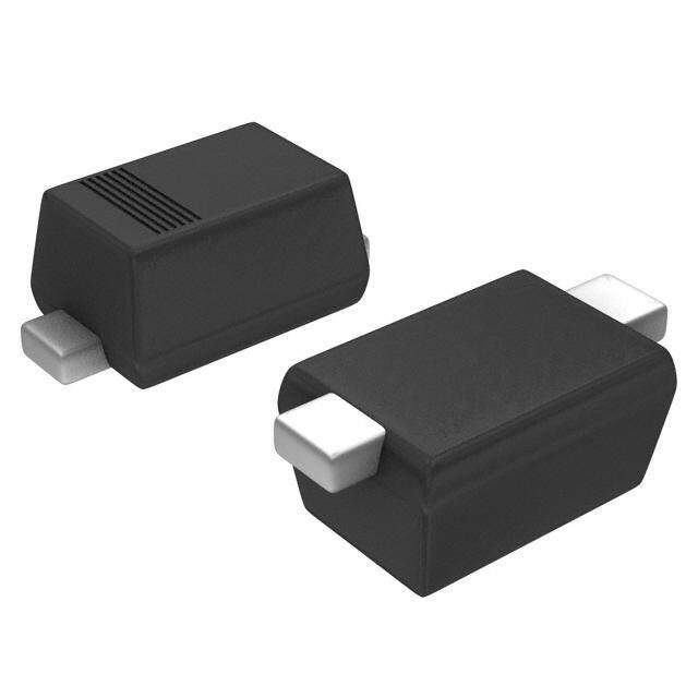
ICGOO电子元器件商城为您提供XBS104V14R-G由TOREX SEMICONDUCTOR设计生产,在icgoo商城现货销售,并且可以通过原厂、代理商等渠道进行代购。 XBS104V14R-G价格参考¥1.94-¥4.93。TOREX SEMICONDUCTORXBS104V14R-G封装/规格:二极管 - 整流器 - 单, 肖特基 表面贴装 二极管 40V 1A SOD-123A。您可以下载XBS104V14R-G参考资料、Datasheet数据手册功能说明书,资料中有XBS104V14R-G 详细功能的应用电路图电压和使用方法及教程。
Torex Semiconductor Ltd. 的 XBS104V14R-G 是一款单个二极管整流器,适用于多种电源管理和电路保护应用。以下是该型号的具体应用场景:

 1. 电源适配器和充电器
XBS104V14R-G 可用于各种电源适配器和充电器中,特别是在需要高效、低损耗的整流功能时。它能够将交流电转换为直流电,确保输出电压稳定且可靠。其高效率和低反向恢复时间特性,使得它在高频开关电源中表现出色。

 2. 消费电子设备
该二极管广泛应用于消费电子产品中,如电视、音响系统、笔记本电脑等。它可以在这些设备的电源部分起到整流作用,确保内部电路获得稳定的直流电源。此外,它还可以用于保护电路,防止电流反向流动,从而避免损坏敏感元件。

 3. 汽车电子
在汽车电子领域,XBS104V14R-G 可用于车载充电器、逆变器和其他电力转换设备中。由于其耐高压和高温性能,能够在严苛的汽车环境中稳定工作。此外,它还适用于电池管理系统中的整流和保护功能,确保电池充放电过程的安全性和可靠性。

 4. 工业控制
在工业自动化和控制系统中,XBS104V14R-G 可以用于电源模块、电机驱动器等设备中。它能够有效地将交流电源转换为直流电源,提供稳定的供电,同时具备良好的抗干扰能力,确保工业设备的正常运行。

 5. 通信设备
对于通信基站、路由器等设备,XBS104V14R-G 可以用于电源模块中,确保设备在不同工作条件下都能获得稳定的直流电源。其低功耗和高效率特性,有助于减少热量产生,延长设备的使用寿命。

 6. LED照明
在LED照明系统中,XBS104V14R-G 可用于驱动电源中,将市电转换为适合LED灯工作的直流电。它不仅能够提高电源转换效率,还能有效抑制电磁干扰,确保照明系统的稳定性和安全性。

总之,XBS104V14R-G 凭借其高性能和可靠性,广泛应用于各类电源管理和电路保护场景,特别适合需要高效整流和低损耗的应用场合。
| 参数 | 数值 |
| 产品目录 | |
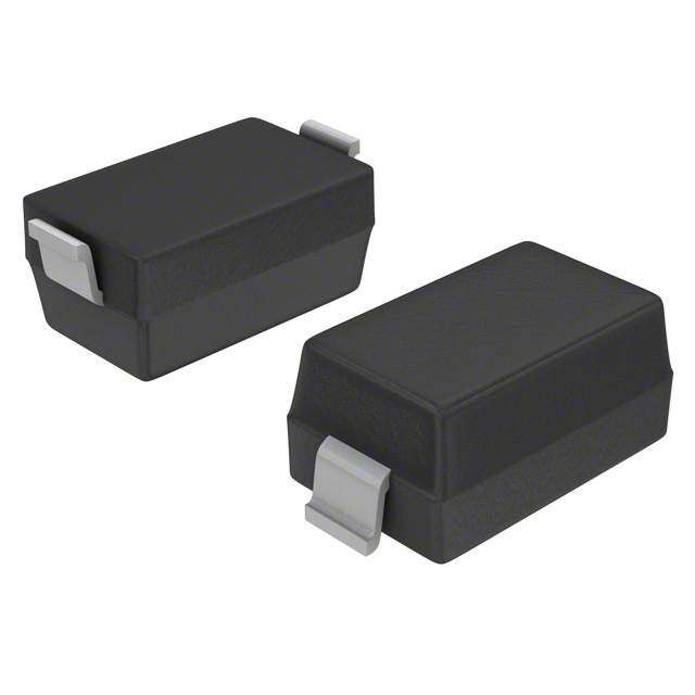
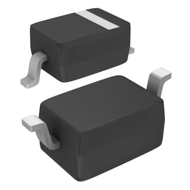
| 描述 | DIODE SCHOTTKY 40V 1A SOD123 |
| 产品分类 | 单二极管/整流器 |
| 品牌 | Torex Semiconductor Ltd |
| 数据手册 | |
| 产品图片 |
|
| 产品型号 | XBS104V14R-G |
| rohs | 无铅 / 符合限制有害物质指令(RoHS)规范要求 |
| 产品系列 | - |
| 不同If时的电压-正向(Vf) | 410mV @ 1A |
| 不同 Vr、F时的电容 | 150pF @ 1V,1MHz |
| 不同 Vr时的电流-反向漏电流 | 2mA @ 40V |
| 二极管类型 | |
| 供应商器件封装 | SOD-123A |
| 其它名称 | 893-1193-6 |
| 包装 | Digi-Reel® |
| 反向恢复时间(trr) | 41ns |
| 安装类型 | 表面贴装 |
| 封装/外壳 | SOD-123 |
| 工作温度-结 | 125°C (最大) |
| 标准包装 | 1 |
| 热阻 | - |
| 电压-DC反向(Vr)(最大值) | 40V |
| 电流-平均整流(Io) | 1A |
| 速度 | 快速恢复 =< 500 ns,> 200mA(Io) |


- 商务部:美国ITC正式对集成电路等产品启动337调查
- 曝三星4nm工艺存在良率问题 高通将骁龙8 Gen1或转产台积电
- 太阳诱电将投资9.5亿元在常州建新厂生产MLCC 预计2023年完工
- 英特尔发布欧洲新工厂建设计划 深化IDM 2.0 战略
- 台积电先进制程称霸业界 有大客户加持明年业绩稳了
- 达到5530亿美元!SIA预计今年全球半导体销售额将创下新高
- 英特尔拟将自动驾驶子公司Mobileye上市 估值或超500亿美元
- 三星加码芯片和SET,合并消费电子和移动部门,撤换高东真等 CEO
- 三星电子宣布重大人事变动 还合并消费电子和移动部门
- 海关总署:前11个月进口集成电路产品价值2.52万亿元 增长14.8%


PDF Datasheet 数据手册内容提取
XBS104V14R-G ETR1610-002 Schottky Barrier Diode, 1A, 40V Type ■FEATURES ■APPLICATIONS Forward Voltage : VF=0.365V (TYP.) ●Rectification Forward Current : I =1A ●Protection against reverse connection of battery F(AV) Repetitive Peak Reverse Voltage : V =40V RM Environmentally Friendly : EU RoHS Compliant, Pb Free ■ABSOLUTE MAXIMUM RATINGS ■PACKAGING INFORMATION Ta=25℃ PARAMETER SYMBOL RATINGS UNIT Repetitive Peak Reverse Voltage VRM 40 V Reverse Voltage (DC) VR 40 V Forward Current (Average) IF(AV) 1 A Non Continuous IFSM 20 A Forward Surge Current*1 Junction Temperature Tj 125 ℃ Storage Temperature Range Tstg -55~+150 ℃ *1: Non continuous high amplitude 60Hz half-sine wave. * When the IC is operated continuously under high load conditions such as high temperature, Cathode Bar high current and high voltage, it may have the case that reliability reduces drastically even if under the absolute maximum ratings. Adequate “Derating” should be taken into consideration while designing. ■MARKING RULE ①: 0 (Product Number) SOD-123A Unit : mm ②: Assembly Lot Number ■PRODUCT NAME PRODUCT NAME DEVICE ORIENTATION XBS104V14R-G SOD-123A(Halogen & Antimony free) XBS104V14R SOD-123A * The “-G” suffix indicates that the products are Halogen and Antimony free as well as being fully RoHS compliant. * The device orientation is fixed in its embossed tape pocket. ■ELECTRICAL CHARACTERISTICS Ta=25℃ LIMITS PARAMETER SYMBOL TEST CONDITIONS UNIT MIN. TYP. MAX. VF1 IF=100mA - 0.23 0.315 V Forward Voltage VF2 IF=500mA - 0.30 0.385 V VF3 IF=1A - 0.365 0.41 V Reverse Current IR VR=40V - 0.25 2 mA Inter-Terminal Capacity Ct V =1V , f=1MHz - 150 - pF R Reverse Recovery Time*2 trr I =I =10mA , irr=1mA - 41 - ns F R *2:trr measurement circuit Bias Device Under test Pulse Generatrix Oscilloscope 1/3
XBS104V14R-G ■TYPICAL PERFORMANCE CHARACTERISTICS (1) Forward Current vs. Forward Voltage (2) Reverse Current vs. Reverse Voltage 1 100 Ta=125℃ Forward Current: I(A) Forward Current I (A)F F 0.00.11 75℃ 2-52℃5℃ Reverse Current: I(mA) R Reverse Current I (mA)R 0.001.1110 T725a5℃=℃100℃ 0.001 0.001 0 0.2 0.4 0.6 0 10 20 30 40 FoFrowrawradr dV Volotaltgaege: VVF (FV (V) ) RReevveerrssee V Vooltlataggee: VVRR ( V(V) ) (3) Forward Voltage vs. Operating Temperature (4) Reverse Current vs. Operating Temperature 0.6 100 V=10V R 5V 1V 10 Forward Voltage: V(V) Forward Voltage V (V)F F 00..24 I0F.=51AA μReverse Current: I(A) R Reverse Current I (uA)R 0.00.111 0.1A 0.0 0.001 -50 0 50 100 150 0 50 100 150 OpOepreartiantgin Tge Tmepmepreartautruer:e T aT (a℃ (℃) ) OOppeerraattiningg TTeemmppeerraattuurree: TTaa ( ℃(℃) ) (5) Inter-Terminal Capacity vs. Reverse Voltage (6) Average Forward Current vs. Operating Temperature 500 2.0 minal Capacity: C(pF) terminal Capacity Ct (pF) 234000000 Forward Current: IF(A) AV Forward Current IF (A)AV 11..05 nter-TerInter-T 100 Average Average 0.5 I 0 0.0 0 10 20 30 40 0 50 100 150 ReRveevresres eV oVlotaltgaeg:e V RV (RV (V) ) OOppeerraattiinngg TTeemmppeerraattuurree : TTaa ((℃℃)) 2/3
XBS104V14R-G 1. The products and product specifications contained herein are subject to change without notice to improve performance characteristics. Consult us, or our representatives before use, to confirm that the information in this datasheet is up to date. 2. We assume no responsibility for any infringement of patents, patent rights, or other rights arising from the use of any information and circuitry in this datasheet. 3. Please ensure suitable shipping controls (including fail-safe designs and aging protection) are in force for equipment employing products listed in this datasheet. 4. The products in this datasheet are not developed, designed, or approved for use with such equipment whose failure of malfunction can be reasonably expected to directly endanger the life of, or cause significant injury to, the user. (e.g. Atomic energy; aerospace; transport; combustion and associated safety equipment thereof.) 5. Please use the products listed in this datasheet within the specified ranges. Should you wish to use the products under conditions exceeding the specifications, please consult us or our representatives. 6. We assume no responsibility for damage or loss due to abnormal use. 7. All rights reserved. No part of this datasheet may be copied or reproduced without the prior permission of TOREX SEMICONDUCTOR LTD. 3/3