ICGOO在线商城 > WR12AS

 Datasheet下载
- 型号: WR12AS
- 制造商: NKK Switches
- 库位|库存: xxxx|xxxx
- 要求:
| 数量阶梯 | 香港交货 | 国内含税 |
| +xxxx | $xxxx | ¥xxxx |
查看当月历史价格
查看今年历史价格
WR12AS产品简介:
ICGOO电子元器件商城为您提供WR12AS由NKK Switches设计生产,在icgoo商城现货销售,并且可以通过原厂、代理商等渠道进行代购。 提供WR12AS价格参考以及NKK SwitchesWR12AS封装/规格参数等产品信息。 你可以下载WR12AS参考资料、Datasheet数据手册功能说明书, 资料中有WR12AS详细功能的应用电路图电压和使用方法及教程。
| 参数 | 数值 |
| 3D型号 | http://www.nkkswitches.com/model.aspx?part=WR12AS&vendor=digikey |
| 产品目录 | |
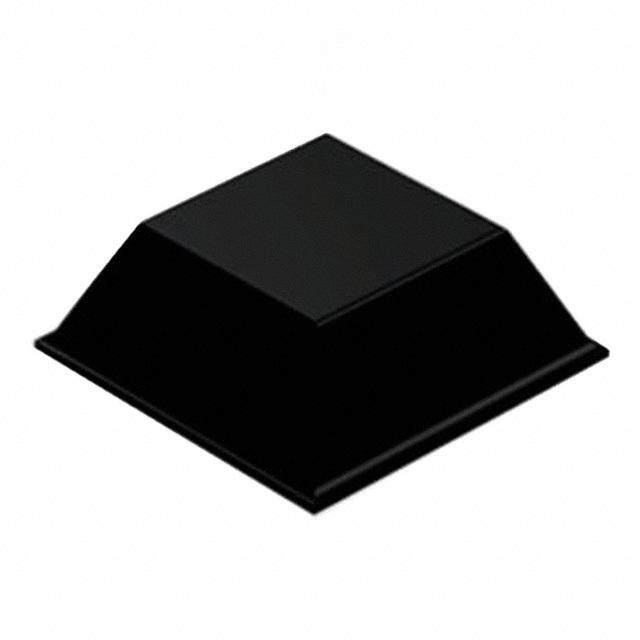
| 描述 | SWITCH ROCKER SPDT 15A 125V翘板开关 SPDT ON-NONE-ON SOLDER LUG SEALED |
| 产品分类 | |
| 品牌 | NKK Switches |
| 产品手册 | |
| 产品图片 |
|
| rohs | 符合RoHS无铅 / 符合限制有害物质指令(RoHS)规范要求 |
| 产品系列 | 翘板开关,NKK Switches WR12ASWR |
| mouser_ship_limit | 该产品可能需要其他文件才能进口到中国。 |
| 数据手册 | |
| 产品型号 | WR12AS |
| RoHS指令信息 | |
| 产品培训模块 | http://www.digikey.cn/PTM/IndividualPTM.page?site=cn&lang=zhs&ptm=7079http://www.digikey.cn/PTM/IndividualPTM.page?site=cn&lang=zhs&ptm=30248http://www.digikey.cn/PTM/IndividualPTM.page?site=cn&lang=zhs&ptm=30583 |
| 产品目录绘图 |
|
| 产品目录页面 | |
| 产品种类 | 翘板开关 |
| 侵入防护 | IP67 - 防尘,防水 |
| 其它名称 | 360-1513 |
| 包装 | 散装 |
| 商标 | NKK Switches |
| 外壳材料 | Polyamide |
| 安装孔 | Rectangular |
| 安装孔大小 | 34.2 mm x 17.2 mm |
| 安装类型 | 面板安装,卡入式 |
| 安装风格 | Panel |
| 工作温度 | -25°C ~ 85°C |
| 工作温度范围 | - 25 C to + 85 C |
| 工厂包装数量 | 1 |
| 开关功能 | 开-开 |
| 执行器 | Rocker |
| 机械寿命 | 30,000 次循环 |
| 标准包装 | 1 |
| 照明 | None |
| 照明电压(标称值) | - |
| 照明类型,颜色 | - |
| 特性 | 环氧树脂密封端子 |
| 电压额定值AC | 250 V |
| 电压额定值DC | 30 V |
| 电气寿命 | 15,000 次循环 |
| 电流额定值 | 15 A |
| 电路 | SPDT |
| 端子密封 | Epoxy |
| 端子类型 | 焊片 |
| 端接类型 | Solder Lug |
| 系列 | WR |
| 致动器标志 | 无标志 |
| 致动器样式 | 凹面(弯曲) |
| 触点形式 | SPDT |
| 触点电镀 | Tin |
| 触点额定值 | 15 A at 125 VAC, 250 VAC, 30 VDC |
| 零件号别名 | WR-12KSE |
| 面板开口尺寸 | 矩形 - 34.20mm x 17.20mm |
| 颜色 | Black |
| 颜色-致动器/盖帽 | 黑 |
| 额定电压-AC | 125V |
| 额定电压-DC | 30V |
| 额定电流 | 15A(AC/DC) |


- 商务部:美国ITC正式对集成电路等产品启动337调查
- 曝三星4nm工艺存在良率问题 高通将骁龙8 Gen1或转产台积电
- 太阳诱电将投资9.5亿元在常州建新厂生产MLCC 预计2023年完工
- 英特尔发布欧洲新工厂建设计划 深化IDM 2.0 战略
- 台积电先进制程称霸业界 有大客户加持明年业绩稳了
- 达到5530亿美元!SIA预计今年全球半导体销售额将创下新高
- 英特尔拟将自动驾驶子公司Mobileye上市 估值或超500亿美元
- 三星加码芯片和SET,合并消费电子和移动部门,撤换高东真等 CEO
- 三星电子宣布重大人事变动 还合并消费电子和移动部门
- 海关总署:前11个月进口集成电路产品价值2.52万亿元 增长14.8%


PDF Datasheet 数据手册内容提取
Series WR Environmentally Sealed Rockers s e gl General Specifications g o T s ker B Electrical Capacity (Resistive Load) c o R Power Level: 15A @ 125/250V AC or 15A @ 30V DC s Other Ratings n utto Contact Resistance: 10 milliohms maximum for solder lug, screw & quick connect terminal models b 30 milliohms maximum for wire lead terminal models h us Insulation Resistance: 200 megohms minimum @ 500V DC P Dielectric Strength: 1,250V AC minimum between contacts for 1 minute minimum B d P 3,750V AC minimum between contacts & case for 1 minute minimum ate Mechanical Life: 30,000 operations minimum min Electrical Life: 15,000 operations minimum for circuit 11 and 12 models Illu 10,000 operations minimum for circuit 13, 15, 18, 19 models e Angle of Throw: 24° bl a m m Materials & Finishes a gr Rocker: Phenylene oxide o Pr Outer Housing: Polyamide (UL94V-0) Inner Case: Melamine (UL94V-0) s ck Cover for Wire Lead Models: Glass fiber reinforced polyamide (UL94V-0) o yl Flange Gasket: Polychloroprene rubber e K Movable Contactor: Copper with silver plating Movable Contacts: Silver alloy plus copper with silver plating Stationary Contacts: Silver alloy plus copper with silver plating s e ari Terminals: Brass with tin plating ot Wire Lead Covers: Heat resistant polyvinyl chloride (Leads are AWG 14) R Environmental Data s Operating Temp Range: –25°C through +85°C (–13°F through +185°F) e d Humidity: 90 ~ 95% humidity for 96 hours @ 40°C (104°F) Sli Vibration: 10 ~ 55Hz with peak-to-peak amplitude of 1.5mm traversing the frequency range & returning in 1 minute; 3 right angled directions for 2 hours Shock: 50G (490m/s2) acceleration (tested in 6 right angled directions, with 5 shocks in each direction) es Front Panel Seal: IP67 of IEC60529, dust tight & water protected during temporary immersion for all models ctil Behind Panel Seal: IP60 of IEC60529, dust tight but not water protected for solder lug, screw & quick connect models a T IP67 of IEC60529, dust tight & water protected during temporary immersion for wire lead models Installation Tilt Soldering Time & Temp: Manual Soldering: See Profile A in Supplement section. Cleaning: Hand clean locally using alcohol based solution. Standards & Certifications h Flammability Standards: UL94V-0 outer housing, inner case, & outer cover on wire lead models c u o UL: File No. E44145 - Recognized only when ordered with marking on switch. T Add “/U” or “/CUL” to end of part number to order UL recognized switch. All models approved at 15A @ 125/250V AC & 15A @ 30V DC. s or EN: No. 61058-1 cat WR11 & WR12 models meet European Norm for 3mm contact gap to prevent contact welds. di In Wiring Material Standards: UL AWM 1015 Recognized at Flammability VW-1. Temperature Range –20°C ~ +105°C; Maximum Load 600V; AWG 14. s e CSA TEW 105 Certified at Temperature Range –20°C ~ +105°C; Maximum Load 600V. ori s s e c c A nt e m e pl p u S B124 www.nkkswitches.com 06/14/19
Series WR Environmentally Sealed Rockers s e Distinctive Characteristics gl g o T s B ker Single unit construction of the flange and outer housing gives added c o R protection from environmental elements. s n o utt Specially designed contact mechanism for breaking hb s u light welds. P B P d e at n Minimal contact bounce achieved with specially mi u designed interlocked switching mechanism. Ill e bl a m m a Heat resistant resin used for outer housing, gr o inner case, and cover on wire lead models Pr meets UL94V-0 flammability standard and s k c provides high arc and tracking resistance. o yl e K Available with solder lug, screw, quick connect, s e and wire lead terminations. ari ot R s e d Sli s e ctil a T Sealed Construction Meets IP60 & IP67 Standards Tilt Actual Size Solder lug, screw, and quick connect terminal models meet IP67 of IEC60529 Standards at front panel (dust tight and water protected for temporary immersion, ch u o patent pending). Behind panel standard is IP60 (dust T tight but not water protected). s or Wire lead models conform fully to IP67 of IEC60529 at c Standards at front and behind panel (dust tight and ndi I water protected for temporary immersion). Switch s base is epoxy sealed and covered by an outer case e ori for further protection from dust and water. (Switches s s e cannot be operated under water. Contact factory for cc A further details regarding operating environment.) nt e m e pl p u S www.nkkswitches.com B125
Series WR Environmentally Sealed Rockers s e gl TYPICAL SWITCH ORDERING EXAMPLE g o T WR 1 2 B S s ker B c o R s n o utt b h s u P B P d Poles Circuits Rockers Terminals e at min 1 SPST 1 ON NONE OFF A Black S Solder Lug with u SPDT Epoxy Seal Ill 2 ON NONE ON *B Ivory ble 3 ON OFF ON *Contact Factory SN Solder Lug without ma for Quick Connect Epoxy Seal m 5 ON NONE (ON) Progra 8 (ON) OFF (ON) with Ivory Rocker T SEpcroexwy LSuega lw ith 9 ON OFF (ON) Screw Lug without s TN ock ( ) = Momentary Epoxy Seal yl e .250” (6.35mm) K F Quick Connect with Epoxy Seal s arie .250” (6.35mm) ot FN Quick Connect R without Epoxy Seal L Wire Lead s e d Sli IMPORTANT: Switches are supplied without UL & cULus marking unless specified. es UL & cULus recognized only when ordered with marking on the switch. ctil Specific models, ratings and ordering instructions are noted on the General a T Specifications page. Tilt DESCRIPTION FOR TYPICAL ORDERING EXAMPLE h uc WR12BS o T ors Ivory Rocker at c di n I SPDT s e ON-NONE-ON Circuit ori s s e Solder Lug Terminals c c A with Epoxy Seal nt e m e pl p u S B126 www.nkkswitches.com
Series WR Environmentally Sealed Rockers s e POLES & CIRCUITS gl g o T Rocker Position ( ) = Momentary Connected Terminals Throw & Schematics s Down Center Up Down Center Up B ker c Note: Terminal numbers are not o Pole Model R actually on wire lead models. s n o 1a (COM) utt SP WR11 ON NONE OFF 1a-1b OPEN OPEN SPST b h 1b us P B WR12 ON NONE ON P d WR13 ON OFF ON 1 (COM) ate n SP WR15 ON NONE (ON) 1-1b OPEN 1-1a SPDT mi WR18 (ON) OFF (ON) 1a 1b Illu e WR19 ON OFF (ON) bl a m m a TYPICAL SWITCH DIMENSIONS gr o Pr Solder Lug Terminals s k c o yl e K NKK P/N This Side .(37.087) (.20.944) Dia Typ (.418.89) Typ s e ari (11.3) Typ 1a ot (41.0) .445 R 1.614(31.018.01) (21.50.04)24° (12.183.84)(13.344.26) 11b (13.344.26)+– 00..03 s e d (.00.381) Typ (17.2)+– 00..03 Sli (12.9) (4.8) (15.8) .677 .508 .189 .622 (24.0) (2.5) (35.4) (17.2) .945 .098 1.394 .677 es ctil a T Panel Thickness .039” ~ .157” WR11 model does not have terminal 1. (1.0mm ~ 4.0mm) WR12AS Tilt Screw Lug Terminals NKK P/N This Side .(37.087) M3.5 x 5 Typ (.62.660) Typ ch u o T (11.2) Typ 1a (14.61.104)(30.0) 24° .441 (12.183.84) 1 (13.344.26)+– 00..03 ators 1.181 (21.50.04) (13.344.26) 1b dic n I (12.9) (8.3) .(013.09) Typ (15.8) (.1677.27)+– 00..03 ories .508 .327 .622 ss (24.0) (2.5) (38.9) (17.2) ce .945 .098 1.531 .677 Ac Panel Thickness nt e .039” ~ .157” m e WR11 model does not have terminal 1. (1.0mm ~ 4.0mm) WR12AT pl p u S www.nkkswitches.com B127
Series WR Environmentally Sealed Rockers s e gl TYPICAL SWITCH DIMENSIONS g o T .250” (6.35mm) Quick Connect Terminals s ker B c o R s NKK P/N This Side .(370.87) (.10.6655)DiaTyp utton .(003.81)Typ b h s u 1a P (41.0) nated PB 1.614(31.018.01) (21.50.04)24˚ (.62.5305).(279.55(1)3.344.26) 11b (.2829.06)(12.183.84) (13.344.26)+– 00..03 mi Illu (3.1.5965) (.1677.27)+– 00..03 e (7.95) (3.6) mabl (.1520.98) (1.04.3.271353) .142 (.1652.82) m (24.0) (2.5) (41.35) (17.2) a .945 .098 1.628 .677 gr o Pr s Panel Thickness k oc .039” ~ .157” eyl WR13AF WR11 model does not have terminal 1. (1.0mm ~ 4.0mm) K Wire Lead Terminals s e ari ot R NKK P/N This Side (7.8) .307 s e d Sli (41.0) 1a ctiles 1.614(31.018.01) (21.50.04)24° (13.344.26) 11b (13.344.26)+– 00..03 a T (.1677.27)+– 00..03 (12.9) (10.0) .508 .394 Tilt (.2944.50) .(029.58) (13.595.55) (270.807.40)+–(20.0) (.1677.72) ch Panel Thickness u o .039” ~ .157” T WR15BL WR11 model does not have terminal 1. (1.0mm ~ 4.0mm) s or STANDARD WIRE COLOR SCHEME at c di n I s Wire leads are covered with heat Terminal Numbers & Wire Colors e ssori rUeLs i1st0a1n5t vainnydl CinS aAc cToErWda 1n0ce5 with 1a 1 1b e cc Standards for Appliance Wiring WR11 Black White A Material (AWM). WR12-19 White Black Red nt e m e pl p u S B128 www.nkkswitches.com
Mouser Electronics Authorized Distributor Click to View Pricing, Inventory, Delivery & Lifecycle Information: N KK Switches: WR11BL/U WR13AL/CUL WR15AT/CUL WR18AF/CUL WR19AF/CUL WR19AL/CUL WR18AL/CUL WR13AF/CUL WR15AL/CUL WR12BF WR11AL/CUL WR11AT/CUL WR19AT/CUL WR13AT/CUL WR15AF/CUL WR12AT/CUL WR18AT/CUL WR11AF/CUL WR12AL/CUL WR12AF/CUL