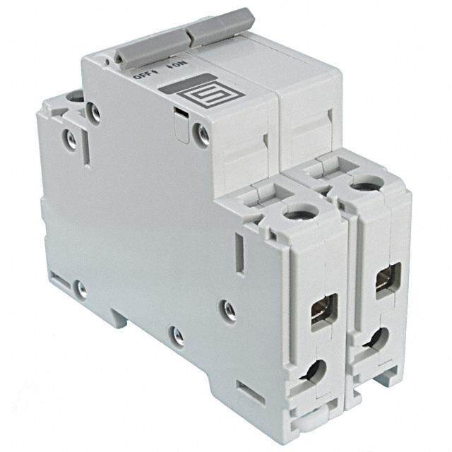
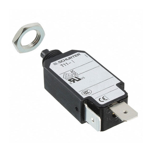
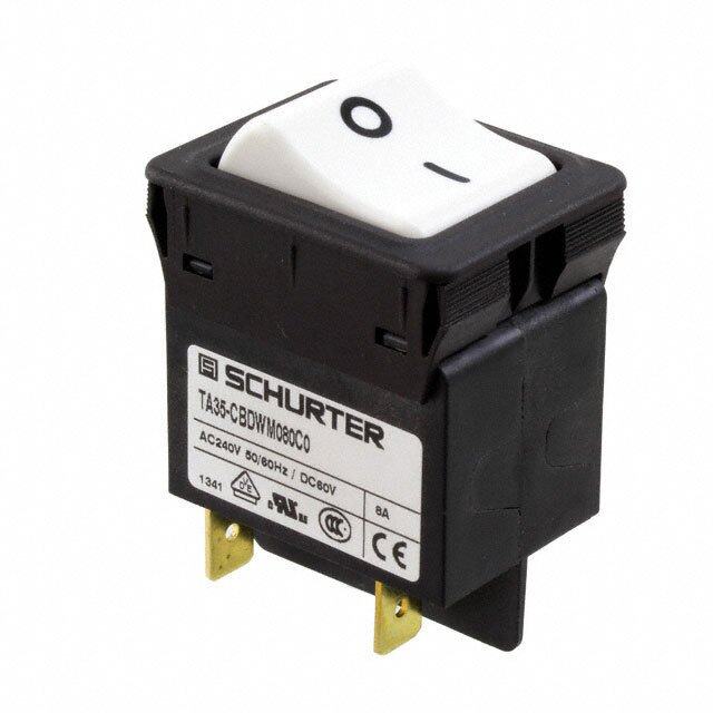
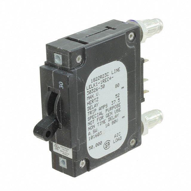
- 型号: W57-XB7A4A10-5
- 制造商: CORCOM/TYCO ELECTRONICS
- 库位|库存: xxxx|xxxx
- 要求:
| 数量阶梯 | 香港交货 | 国内含税 |
| +xxxx | $xxxx | ¥xxxx |
查看当月历史价格
查看今年历史价格
W57-XB7A4A10-5产品简介:
ICGOO电子元器件商城为您提供W57-XB7A4A10-5由CORCOM/TYCO ELECTRONICS设计生产,在icgoo商城现货销售,并且可以通过原厂、代理商等渠道进行代购。 W57-XB7A4A10-5价格参考¥10.83-¥10.83。CORCOM/TYCO ELECTRONICSW57-XB7A4A10-5封装/规格:断路器, 。您可以下载W57-XB7A4A10-5参考资料、Datasheet数据手册功能说明书,资料中有W57-XB7A4A10-5 详细功能的应用电路图电压和使用方法及教程。
| 参数 | 数值 |
| 3D型号 | http://www.te.com/commerce/DocumentDelivery/DDEController?Action=srchrtrv&DocNm=1423675-3&DocType=Customer+View+Model&DocLang=English |
| 产品目录 | |
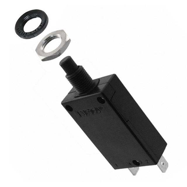
| 描述 | CIR BRKR THRM 5A 250VAC断路器 5A PUSH TO RESET |
| 产品分类 | |
| 品牌 | TE Connectivity / P&B |
| 产品手册 | http://www.te.com/catalog/pn/en/W57-XB7A4A10-5?RQPN=W57-XB7A4A10-5 |
| 产品图片 |
|
| rohs | RoHS 合规性豁免无铅 / 符合限制有害物质指令(RoHS)规范要求 |
| 产品系列 | 断路器,TE Connectivity / P&B W57-XB7A4A10-5W57,Potter & Brumfield |
| mouser_ship_limit | 该产品可能需要其他文件才能进口到中国。 |
| 数据手册 | |
| 产品型号 | W57-XB7A4A10-5 |
| 产品 | Thermal Circuit Breakers |
| 产品培训模块 | http://www.digikey.cn/PTM/IndividualPTM.page?site=cn&lang=zhs&ptm=6307 |
| 产品目录绘图 |
|
| 产品目录页面 | |
| 产品种类 | |
| 产品类型 | Supplementary Protector |
| 介质强度 | 1.5 kVAC |
| 其它名称 | 1423675-3 |
| 单位重量 | 14.300 g |
| 商标 | TE Connectivity / P&B |
| 安装类型 | 面板安装 |
| 安装风格 | Panel |
| 宽度 | 14.6 mm |
| 工作温度范围 | 0 C to + 60 C |
| 工厂包装数量 | 200 |
| 执行器类型 | Pushbutton |
| 断路器类型 | 热敏式 |
| 极数 | 1 Pole |
| 标准包装 | 200 |
| 照明 | Not Illuminated |
| 照明电压(标称值) | - |
| 特色产品 | http://www.digikey.com/product-highlights/cn/zh/te-connectivity-circuit-breakers/3831 |
| 电压额定值 | 250 VAC |
| 电压额定值AC | 250 V |
| 电流额定值 | 5 A |
| 电路功能 | Series Trip |
| 相关产品 | /product-detail/zh/1-1423696-5/PB1863-ND/1427139 |
| 端接类型 | Quick Connect |
| 类型 | Push to Reset only Circuit Breaker |
| 系列 | W57 |
| 致动器类型 | 按下复位 |
| 跳闸时间 | 5 s to 40 s |
| 长度 | 22.6 mm |
| 零件号别名 | 1423675-3 |
| 颜色 | White |
| 额定电压-AC | 250V |
| 额定电压-DC | - |
| 额定电流 | 5A |
| 高度 | 29.2 mm |





- 商务部:美国ITC正式对集成电路等产品启动337调查
- 曝三星4nm工艺存在良率问题 高通将骁龙8 Gen1或转产台积电
- 太阳诱电将投资9.5亿元在常州建新厂生产MLCC 预计2023年完工
- 英特尔发布欧洲新工厂建设计划 深化IDM 2.0 战略
- 台积电先进制程称霸业界 有大客户加持明年业绩稳了
- 达到5530亿美元!SIA预计今年全球半导体销售额将创下新高
- 英特尔拟将自动驾驶子公司Mobileye上市 估值或超500亿美元
- 三星加码芯片和SET,合并消费电子和移动部门,撤换高东真等 CEO
- 三星电子宣布重大人事变动 还合并消费电子和移动部门
- 海关总署:前11个月进口集成电路产品价值2.52万亿元 增长14.8%


PDF Datasheet 数据手册内容提取
Catalog 1308242 Issued 4-15 (PDF Rev. 04-15) Potter & Brumfield W57 series Compact, Push To Reset Only P&B Thermal Circuit Breaker Features Insulation Resistance: 100 megohms. • New, compact design. Maximum Operating Voltages: 50VDC; 250VAC, 50/60 Hz. • 3 to 20 amp ratings. Interrupt Capacity: 1,000 amps in accordance with UL standard 1077. • Cannot be manually tripped. Resettable Overload Capacity: Ten times rated current. • Button extends for visual trip indication. Reset Time: 60 seconds. • Push button to reset breaker. • Numerous mounting and termination options. • Optional bottom marking of amperage rating. Typical Resistance vs. Current Rating @ +25°C Agency Approvals Current Typical Current Typical Rating Resistance Rating Resistance W57 series is UL1077 Recognized as Supplementary Protectors, in Amps in Ohms in Amps in Ohms File E69543, for Canada and the United States. Available models meet Ignition Protection requirements in accordance with UL1500. 3.0 0.083 8.0 0.031 Approved to VDE 0642/EN60934 (Circuit Breakers for Equipment) 4.0 0.062 10.0 0.025 License Number 40007874 (excludes models rated 3-4A and >15A). 5.0 0.050 12.0 0.021 CCC mark compliant, certificate 2004010307123217. 6.0 0.042 15.0 0.017 7.0 0.036 20.0 0.012 Users should thoroughly review the technical data before selecting a product part number. It is recommended that users also seek out the pertinent approvals files of the agencies/labora-tories and review them to confirm the product meets the requirements for a given application. Mechanical/Environmental Data Electrical Data @ 25°C Operating Temperature Range: 0°C to +60°C. Calibration: Will continuously carry 100% of rating. Termination: .250” (6.35mm) quick connects. May trip between 101% and 134%, but must trip at 135% of Mounting: Various options. See Ordering Information and drawings. rating within one hour at +25°C. Approximate Weight: 0.5 oz. (14.3g). Dielectric Strength: 1,500VAC (60 seconds). Time vs. Current Trip Curve @ +25°C Outline Dimensions 1000 .465(cid:18) .889(cid:18) .457(cid:18) Overload Trip Times (11.8) (22.6) (11.6) 900 100% No Trip 135% Trip in 1 hour 800 200% 4.0 - 40.0 Sec. 300% 1.2 - 12.0 Sec. ent 700 450000%% 00..64 -- 52..08 SSeecc.. (12.91.52(cid:18))(.1678.95(cid:18)) .(370.73)(cid:18) c nt As A Peraker Rating650000 1068000000%%% 000..11.283 --- 001...789 SSSeeeccc... SEE TERFMORIN DALE TDARILAWINGS(cid:18) MOUSBNEUTESI NMHGOIN HUGAN ARTNDINDWG(cid:18)(cid:18)ARE(cid:18) d CurreOf Bre430000 .0(.381)(cid:18).(120.62)(cid:18) DRAWINGS FOR DETAIL a .575(cid:18) Lo 200 (14.6) 135 100 0 Optional Protective Boot .1 1 10 100 1000 10,000 Silicone rubber boot is bonded to integral alumimum nut. Time In Seconds Ambient Compensation Table 1-1423696-5 .63 DIA. Black boot for W57 with Ambient Rating Correction Factor (16.0) 3/8”-24 bushing. Temperature To use this chart: Divide the breaker in °C 3-4A Models 5-20A Models rating by the correction factor to .622 -10 .70 .77 determine the compensated rating. (15.8) 0 .75 .85 Calculate the overloads in terms of 10 .82 .90 the compensated rating to use the 20 .90 .95 published trip curve. 25 1.00 1.00 Do not use these devices outside 1-1423696-6 30 1.10 1.05 their specified operating temperature .7(107 D.8IA). Clear boot for W57 with 40 1.25 1.15 ranges. M11 X 1.0 bushing. 50 1.61 1.25 .799 60 2.15 1.40 (20.3) Revised 04-15 Dimensions are in inches over Dimensions are shown for reference USA: 1-800-522-6752 South America: 55-11-2103-6000 www.te.com (millimeters) unless otherwise purposes only. Specifications and Canada: 1-905-470-4425 Hong Kong: 852-2735-1628 1 specified. availability subject to change. Mexico: 01-800-733-8926 Japan: 81-44-844-8013 C. America: 52-55-1106-0803 UK: 44-8706-080208
Catalog 1308242 Issued 4-15 (PDF Rev. 04-15) Potter & Brumfield Ordering Information > W 57 -X B 1 A 4 A 1 0 -4 Typical Part No. 1. Designator: W = Circuit breaker 2. Series Number: 57 = Compact, Single Pole, Push-to-Reset, Thermal Model 3. Circuit Function: X = Series Trip 4. Button Color & Rate Marking: A = White, plain, no rate marking G = White, black rate marking (horizontal) B = White, red rate marking (vertical) H = Black, white rate marking (vertical) C = White, black rate marking (vertical) I = Red, plain, no rate marking D = Black, plain, no rate marking J = Black, no rate marking on button, E = Black, white rate marking (horizontal) white rate marking on bottom of F = White, red rate marking (horizontal) case between terminals. 5. Mounting Bushing: 1 = Plastic, 9.8mm (double D) X 9.6mm long, M11x1 threads, (similar to 7/16”), hex base 2 = Plastic, 3/8” (single D) x 10.5mm long, 3/8”x24 threads, hex base 4 = Plastic, snap-in type 5 = Metal, 9.8mm (double D) X 9.6mm long, M11x1 threads, (similar to 7/16”), round base 6 = Metal, 3/8” (single D) x 10.5mm long, 3/8”x24 threads, hex base 7 = Metal, 10.8mm (double D) x 9.6mm long, M12x1 threads, (similar to 15/32”), round base 8 = Metal, 3/8” (double D) x 10.0mm long, 3/8”x24 threads, hex base Notes: Codes 1 and 3 are similar in size to 7/16” bushings (not exact equivalent). Code 7 is similar in size to a 15/32” bushing (not exact equivalent) 6. Terminals: (see drawings for detail) A = Quick connect .250” (6.35mm) straight B = Quick connect .250” (6.35mm) , bent 90° C = Quick connect .250” (6.35mm) , bent 45° D = Quick connect .250” (6.35mm) , bent 90° E = Quick connect .250” (6.35mm) , bent 90°, PCB compatible F = Quick connect .250” (6.35mm) , bent 90°, PCB compatible G = Quick connect .250” (6.35mm) , straight (smaller hole) H = One quick connect .250” (6.35mm) , one #8-32 screw bent 90° I = Same as F above, but amperage marking reversed. 7. Mounting Hardware: 4 = Metal knurled nut/hex nut 7 = Plastic knurled nut 6 = Metal hex nut 8 = Plastic knurled nut with small hole 12 = Metal knurled nut 22 = Plastic knurled nut, metal lockwasher 15 = 2 metal hex nuts, metal lockwasher 18 = Metal hex nut, metal lockwasher 99 = None 8. Mounting Hardware Packaging: A = Assembled to bushing B = Bulk unassembled C = No mounting hardware. 9. Maximum Operating Voltage (AC): 1 = 250VAC 2 = 125VAC/50VDC 10. Nameplate: 0 = None 1 = Embossed aluminum 2 = Silver color printing on black color 3 = Black color printing on silver color 11. Specify Amp Rating: 3† 4† 5 6 7 8 10 12 15 20† †Not VDE 12. UL Recognition: Leave Blank = UL1077 recognized breaker M = Model meeting Ignition Protection requirements in accordance with UL1500, in addition to UL1077 recognition† †Not VDE Our authorized distributors are more likely to stock the following items for immediate delivery. W57-XB1A4A10-5 W57-XB1A4A10-15 W57-XB1A7A10-5 W57-XB1A7A10-15 W57-XB1A4A10-10 W57-XB1A4A10-20 W57-XB1A7A10-10 W57-XB1A7A10-20 ORDERING NOTE: Mounting hardware can be ordered separately. Some options are subject to extended leadtimes and significant minimum order quantities. Mounting Bushings and Recommended Panel Cutouts .338 .059 .4(1411.+2+.0.028, ,- .-0.0) .043 (8.6) .3(486.8 + +.0.20,8 -,. 0-.)0 .6(1360±±..1030)5 (1.5) (1.1) .386 .394+.008, -.0 .382 +.008, -.0 .543±.005 (9.8) (10.0+.2, -.0) (9.7 +.2, -.0) (13.8±.13) .378 .394 (9.6) (10.0) Option 1 – M11 X 1.0 Thread Option 2 & 6 – 3/8” - 24UNF Thread Option 4 – Snap In Option .441+.008, -.0 .480 +.008, -.0 .382 +.008, -.0 .059 (11.2+.2, -.0) .059 (12.2 +.2, -.0) .043 (9.7 +.2, -.0) (1.5) (1.5) (1.1) .386 .394+.008, -.0 .425 .433 +.008, -.0 .303 .311 +.008, -.0 (9.8) (10.0+.2, -.0) (10.8) (11.0 +.2, -.0) (7.7) (7.9 +.2, -.0) .378 .378 .394 (9.6) (9.6) (10.0) Option 5 – M11 X 1.0 Thread Option 7 – M12 X 1.0 Thread Option 8 – 3/8” - 24UNF Thread Revised 04-15 Dimensions are in inches over Dimensions are shown for reference USA: 1-800-522-6752 South America: 55-11-2103-6000 www.te.com (millimeters) unless otherwise purposes only. Specifications and Canada: 1-905-470-4425 Hong Kong: 852-2735-1628 2 specified. availability subject to change. Mexico: 01-800-733-8926 Japan: 81-44-844-8013 C. America: 52-55-1106-0803 UK: 44-8706-080208
Catalog 1308242 Issued 4-15 (PDF Rev. 04-15) Potter & Brumfield Termination Options .(132.26.()1 32.26) .(135.94.( 1 3±±5. 9 40. 0 .±±3.1(1 3) 0.2.0.2631) ). (132.26.()1 32.26) .(148..(1631.(5)1. 4948. 6 1±±) 0.0.31) .(.0(2139.2.5826.( 0 )2± ±9. 5 80. 0 .±±31.(1 )4 0.8.0.6131) ) .(148.61.()1 48..1611) 0.1 .((012290..588 ( ) 2± ±D. 8 0I.A)0. 3D1.) IA..(148.61) ..101701. 0 ((271.1.88 )() 1 DD.8IIAA) .D.IA. .071 (1.8) DIA. Option A Option C Option D Option E Option B Option F or I Option G Option H .250 QC .250 QC .250 QC .250 QC/PCB .250 QC .250 QC/PCB .250 QC Straight .250 QC Straight Straight 45° 90° 270° 90 ° 270 ° (small hole) with #8-32 Load Term. Bent 90° Mounting Hardware Options Optional Bottom Marking of Rating ALTERNATE TEETH TWISTEDALTERNATE TEETH TWISTED A A A AA A A IN OPAPOSITE DIRECTIONS IN OPPOSITE DIRECTIONS 2 X .059 DIA. 2 X .059 DIA. (1.5) (1.5) A A B B B BB 84B° 56° B 84° 5B6° B B Knurled Nut Hex Nut Integrated Knurled Nut Lockwasher with Small Holes Mounting Hardware Dimensions Dimension Bushing Plastic Integrated Plastic Metal Metal Lockwasher Code Diameter Knurled Nut Knurled Nut w/Holes Knurled Nut Hex Nut 3/8” .74 (18.8) – .56 (14.2) .55 (14.0) .49 (12.5) A M11 .74 (18.8) .74 (18.8) .59 (15.0) .55 (14.0) .587 (14.9) M12 – – .59 (15.0) .55 (14.0) .626 (15.9) 3/8” .126 (3.2) – .079 (2.0) .079 (2.0) .02 (.5) B M11 .126 (3.2) .13 (3.3) .102 (2.6) .118 (3.0) .02 (.5) M12 – – .102 (2.6) .079 (2.0) .02 (.5) Mounting Hardware Ordering Information Mounting Bushing Mounting Bushing Plastic Integrated Plastic Metal Metal Lockwasher Material Code Knurled Nut Knurled Nut w/Holes Knurled Nut Hex Nut Plastic 1 (M11) – 1423696-8 2-1423696-2 – – 2 (3/8”) – 1423696-2 – – – 5 (M11) – – 1423696-4 1423696-6 1-1423696-2 Metal 6 (3/8”) – – 1-1423696-0 1423696-3 1-1423696-1 7 (M12) – – 1423696-5 1423696-7 1-1423696-3 8 (3/8”) – – 1-1423696-0 1423696-3 1-1423696-1 Nameplates .854 DIA.(cid:23) .945 DIA.(cid:23) (21.7) (24.0) .016 (.4) THICK .016 (.4) THICK Embossed Imprinted Aluminum Aluminum (Either Silver on Black or Black on Silver) Revised 04-15 Dimensions are in inches over Dimensions are shown for reference USA: 1-800-522-6752 South America: 55-11-2103-6000 www.te.com (millimeters) unless otherwise purposes only. Specifications and Canada: 1-905-470-4425 Hong Kong: 852-2735-1628 3 specified. availability subject to change. Mexico: 01-800-733-8926 Japan: 81-44-844-8013 C. America: 52-55-1106-0803 UK: 44-8706-080208

 Datasheet下载


