- 型号: W2H15C4738AT1A
- 制造商: AVX
- 库位|库存: xxxx|xxxx
- 要求:
| 数量阶梯 | 香港交货 | 国内含税 |
| +xxxx | $xxxx | ¥xxxx |
查看当月历史价格
查看今年历史价格
W2H15C4738AT1A产品简介:
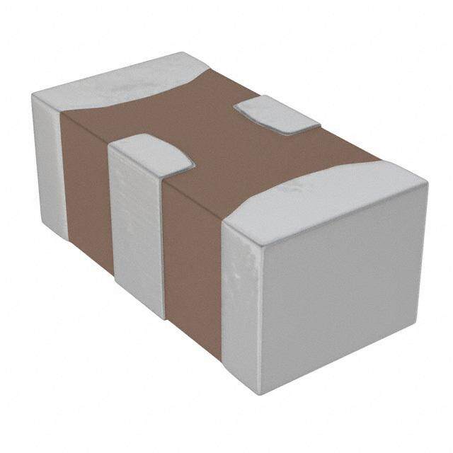
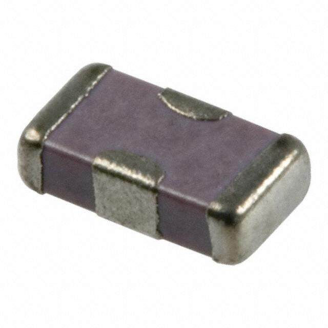
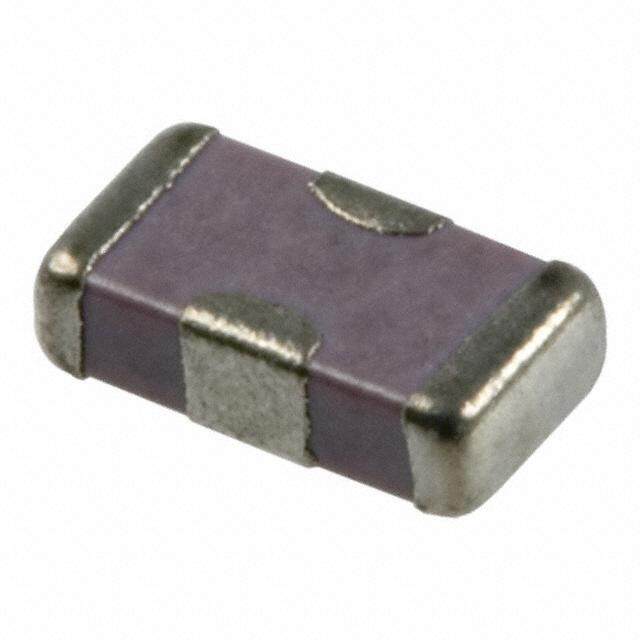
ICGOO电子元器件商城为您提供W2H15C4738AT1A由AVX设计生产,在icgoo商城现货销售,并且可以通过原厂、代理商等渠道进行代购。 W2H15C4738AT1A价格参考¥0.85-¥4.34。AVXW2H15C4738AT1A封装/规格:馈通式电容器, 0.047µF Feed Through Capacitor 50V 2A 150 mOhm 0805 (2012 Metric), 4 PC Pad。您可以下载W2H15C4738AT1A参考资料、Datasheet数据手册功能说明书,资料中有W2H15C4738AT1A 详细功能的应用电路图电压和使用方法及教程。
| 参数 | 数值 |
| 产品目录 | |
| DC电阻(DCR) | 150 毫欧 |
| 描述 | CAP FEEDTHRU 47000PF 50VX7R 0805馈通电容器 50volt .047uF X7R |
| 产品分类 | |
| 品牌 | AVX Corporation |
| 产品手册 | |
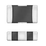
| 产品图片 |
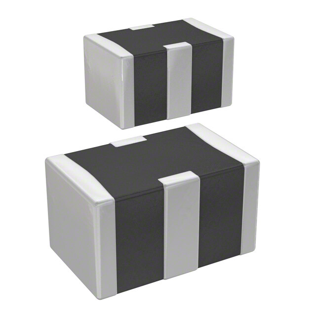
|
| rohs | 符合RoHS无铅 / 符合限制有害物质指令(RoHS)规范要求 |
| 产品系列 | 馈通电容器,AVX W2H15C4738AT1AW2H |
| 数据手册 | |
| 产品型号 | W2H15C4738AT1A |
| 产品 | Three Terminal Filter Capacitors |
| 产品目录绘图 |
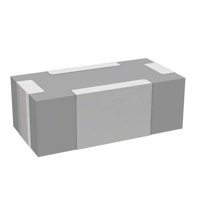
|
| 产品目录页面 | |
| 产品种类 | 馈通电容器 |
| 其它名称 | 478-5476-6 |
| 包装 | Digi-Reel® |
| 商标 | AVX |
| 外壳宽度 | 1.25 mm |
| 外壳长度 | 2.01 mm |
| 外壳高度 | 1.14 mm |
| 大小/尺寸 | 0.079" 长 x 0.049" 宽(2.01mm x 1.25mm) |
| 容差 | - 20 %, + 50 % |
| 封装 | Reel |
| 封装/外壳 | 0805(2012 公制),4 PC 板 |
| 封装/箱体 | 0805 (2012 metric) |
| 工作温度 | -55°C ~ 125°C |
| 工厂包装数量 | 4000 |
| 接地端子 | 0.46 mm |
| 最大工作温度 | + 125 C |
| 最大直流电阻 | 150 mOhms |
| 最小工作温度 | - 55 C |
| 标准包装 | 1 |
| 温度系数 | X7R |
| 电压 | 50V |
| 电压额定值DC | 50 V |
| 电容 | 0.047µF |
| 电流 | 2A |
| 电流额定值 | 2 A |
| 端接类型 | SMD/SMT |
| 类型 | High Current Feed Through Capacitors |
| 系列 | W2H |
| 绝缘电阻 | 1 Ohms |
| 螺纹尺寸 | - |
| 频率范围 | 5 GHz |
| 高度(最大值) | 0.045"(1.14mm) |




- 商务部:美国ITC正式对集成电路等产品启动337调查
- 曝三星4nm工艺存在良率问题 高通将骁龙8 Gen1或转产台积电
- 太阳诱电将投资9.5亿元在常州建新厂生产MLCC 预计2023年完工
- 英特尔发布欧洲新工厂建设计划 深化IDM 2.0 战略
- 台积电先进制程称霸业界 有大客户加持明年业绩稳了
- 达到5530亿美元!SIA预计今年全球半导体销售额将创下新高
- 英特尔拟将自动驾驶子公司Mobileye上市 估值或超500亿美元
- 三星加码芯片和SET,合并消费电子和移动部门,撤换高东真等 CEO
- 三星电子宣布重大人事变动 还合并消费电子和移动部门
- 海关总署:前11个月进口集成电路产品价值2.52万亿元 增长14.8%


PDF Datasheet 数据手册内容提取
AVX Multilayer Ceramic SMD Feedthru Capacitors Commercial, Automotive, High Current, RoHS & SnPb Termination m o c . x v a w. w w Version 17.5
Feedthru 0805/1206 Capacitors Table of Contents W2F/W2H/W3F Series - 0805 & 1206 Feedthru Chips Commercial, Automotive, High Current, RoHS & SnPb . . . . . . . . . . . . . . . . . . . . . . . . . . . 1 Application Notes . . . . . . . . . . . . . . . . . . . . . . . . . . . . . . . . . . . . . . . . . . . . . . . . . . . 5
Feedthru 0805/1206 Capacitors W2F/W3F Series, High Current W2H Series Commercial, Automotive, High Current, RoHS & SnPb GENERAL DESCRIPTION W2F/W2H W3F Series Available in both a standard 0805 and 1206 size, AVX’s line Series 1206 of feedthru capacitors are ideal choices for EMI suppres- sion, broadband I/O filtering, or Vcc power line condition- 0805 ing. The unique construction of a feedthru capacitor pro- vides low parallel inductance and offers excellent decou- pling capability for all high di/dt environments and provides significant noise reduction in digital circuits to <5 GHz. A large range of capacitor values are available in either NP0 or X7R ceramic dielectrics. AVX FeedThru filters are AEC Q200 qualified. High reliability screening options, and SnPb termination are available for spacecraft designs. ELECTRICAL PARAMETERS AVX Part Number Rated Case Size Capacitance Capacitance Rated Type SnPb Termination Automotive w/ SnPb Current Dielectric (EIA) Standard Automotive (pF) Tolerance DC Voltage Finish Termination Finish (Amps) 0805 W2H11A2208ATxx L2H11A2208ABxx W2H11A22084Txx L2H11A22084Bxx 22 +50%, -20% 100V 0.5 NP0 SIGNAL LINE - INPUT OUTPUT ent 00880055 WW22HH1111AA14071088AATTxxxx LL22HH1111AA14071088AABBxxxx WW22HH1111AA1407108844TTxxxx LL22HH1111AA1407108844BBxxxx 14070 ++5500%%,, --2200%% 110000VV 00..55 NNPP00 r 0805 W2H11A2218ATxx L2H11A2218ABxx W2H11A22184Txx L2H11A22184Bxx 220 +50%, -20% 100V 0.5 NP0 GROUND r u 0805 W2H11A4718ATxx L2H11A4718ABxx W2H11A47184Txx L2H11A47184Bxx 470 +50%, -20% 100V 0.5 NP0 C 0805 W2H15C1028ATxx L2H15C1028ABxx W2H15C10284Txx L2H15C10284Bxx 1000 +50%, -20% 50V 1.0 X7R h 0805 W2H15C1038ATxx L2H15C1038ABxx W2H15C10384Txx L2H15C10384Bxx 10000 +50%, -20% 50V 1.0 X7R g Hi 0805 W2H15C2238ATxx L2H15C2238ABxx W2H15C22384Txx L2H15C22384Bxx 22000 +50%, -20% 50V 1.0 X7R 0805 W2H15C4738ATxx L2H15C4738ABxx W2H15C47384Txx L2H15C47384Bxx 47000 +50%, -20% 50V 2.0 X7R 0805 W2H13C1048ATxx L2H13C1048ABxx W2H13C10484Txx L2H13C10484Bxx 100000 +50%, -20% 25V 2.0 X7R 0805 W2F11A2208ATxx L2F11A2208ABxx W2F11A22084Txx L2F11A22084Bxx 22 +50%, -20% 100V 0.3 NP0 0805 W2F11A4708ATxx L2F11A4708ABxx W2F11A47084Txx L2F11A47084Bxx 47 +50%, -20% 100V 0.3 NP0 0805 W2F11A1018ATxx L2F11A1018ABxx W2F11A10184Txx L2F11A10184Bxx 100 +50%, -20% 100V 0.3 NP0 0805 W2F11A2218ATxx L2F11A2218ABxx W2F11A22184Txx L2F11A22184Bxx 220 +50%, -20% 100V 0.3 NP0 0805 W2F11A4718ATxx L2F11A4718ABxx W2F11A47184Txx L2F11A47184Bxx 470 +50%, -20% 100V 0.3 NP0 0805 W2F15C1028ATxx L2F15C1028ABxx W2F15C10284Txx L2F15C10284Bxx 1000 +50%, -20% 50V 0.3 X7R 0805 W2F15C2228ATxx L2F15C2228ABxx W2F15C22284Txx L2F15C22284Bxx 2200 +50%, -20% 50V 0.3 X7R 0805 W2F15C4728ATxx L2F15C4728ABxx W2F15C47284Txx L2F15C47284Bxx 4700 +50%, -20% 50V 0.3 X7R d 0805 W2F15C1038ATxx L2F15C1038ABxx W2F15C10384Txx L2F15C10384Bxx 10000 +50%, -20% 50V 0.3 X7R r 0805 W2F15C2238ATxx L2F15C2238ABxx W2F15C22384Txx L2F15C22384Bxx 22000 +50%, -20% 50V 0.3 X7R a d 0805 W2F15C4738ATxx L2F15C4738ABxx W2F15C47384Txx L2F15C47384Bxx 47000 +50%, -20% 50V 0.3 X7R n 1206 W3F11A2208ATxx L3F11A2208ABxx W3F11A22084Txx L3F11A22084Bxx 22 +50%, -20% 100V 0.3 NP0 a t 1206 W3F11A4708ATxx L3F11A4708ABxx W3F11A47084Txx L3F11A47084Bxx 47 +50%, -20% 100V 0.3 NP0 S 1206 W3F11A1018ATxx L3F11A1018ABxx W3F11A10184Txx L3F11A10184Bxx 100 +50%, -20% 100V 0.3 NP0 1206 W3F11A2218ATxx L3F11A2218ABxx W3F11A22184Txx L3F11A22184Bxx 220 +50%, -20% 100V 0.3 NP0 1206 W3F11A4718ATxx L3F11A4718ABxx W3F11A47184Txx L3F11A47184Bxx 470 +50%, -20% 100V 0.3 NP0 1206 W3F15C1028ATxx L3F15C1028ABxx W3F15C10284Txx L3F15C10284Bxx 1000 +50%, -20% 50V 0.3 X7R 1206 W3F15C2228ATxx L3F15C2228ABxx W3F15C22284Txx L3F15C22284Bxx 2200 +50%, -20% 50V 0.3 X7R 1206 W3F15C4728ATxx L3F15C4728ABxx W3F15C47284Txx L3F15C47284Bxx 4700 +50%, -20% 50V 0.3 X7R 1206 W3F15C1038ATxx L3F15C1038ABxx W3F15C10384Txx L3F15C10384Bxx 10000 +50%, -20% 50V 0.3 X7R 1206 W3F15C2238ATxx L3F15C2238ABxx W3F15C22384Txx L3F15C22384Bxx 22000 +50%, -20% 50V 0.3 X7R 1206 W3F15C4738ATxx L3F15C4738ABxx W3F15C47384Txx L3F15C47384Bxx 47000 +50%, -20% 50V 0.3 X7R xx = Packaging and quantity code - see "How To Order" section. Parameter High Current Standard SIGNAL LINE - INPUT OUTPUT InsulationResistance (Minimum) 1000 MΩ 1000 MΩ DC Resistance <0.15 Ω <0.60 Ω GROUND Operating Temperature -55C to +125C HOW TO ORDER W 3 F 1 5 C 223 8 A T 3 A Style Size Feedthru Number Voltage Dielectric Capacitance Capacitance Failure Rate Termination Packaging Code Quantity W = Plated Ni & Sn 2 = 0805 F = Feedhtru of 1 = 100V A = NP0 Code Tolerance A = Not Applicable T = Plated Ni & Sn (Reel Size) Code L = Plated SnPb 3 = 1206 H= High Current E l e ments 5 = 50V C = X7R 8 = +50/-20% 4 = AUTOMOTIVE B* = Plated SnPb 1 & 2 = 7" Reel (Pcs./Reel) Feedthru *Not RoHS Compliant Embossed Tape F = 1,000 3 & 4 = 13" Reel A = 2,000, Embossed Tape 4,000 or 10,000 050817 1
Feedthru 0805/1206 Capacitors W2F/W3F Series, High Current W2H Series Commercial, Automotive, High Current, RoHS & SnPb Common Ground Feedthru Pad Feedthru Pad L X CL S BL T W BW EW Common Ground DIMENSIONS L W T BW BL EW X S 0805 MM 2.01 ± 0.20 1.25 ± 0.20 1.14 Max. 0.46 ± 0.10 0.18 + 0.25 -0.08 0.25 ± 0.13 1.02 ± 0.10 0.23 ± 0.15 (in.) (0.079 ± 0.008) (0.049 ± 0.008) (0.045 Max.) (0.018 ±0.004) (0.007 + 0.010 -0.003) (0.010 ± 0.005) (0.040 ± 0.004) (0.009 ± 0.006) 1206 MM 3.20 ± 0.20 1.60 ± 0.20 1.27 Max. 0.89 ± 0.10 0.18 + 0.25 -0.08 0.38 ± 0.18 1.60 ± 0.10 0.46 ± 0.15 (in.) (0.126 ± 0.008) (0.063 ± 0.008) (0.050 Max.) (0.035 ± 0.004) (0.007 + 0.010 -0.003) (0.015 ± 0.007) (0.063 ± 0.004) (0.018 ± 0.006) T P P S W C L RECOMMENDED SOLDER PAD LAYOUT (TYPICAL DIMENSIONS) T P S W L C 0805 MM 3.45 0.51 0.76 1.27 1.02 0.46 (in.) (0.136) (0.020) (0.030) (0.050) (0.040) (0.018) 1206 MM 4.54 0.94 1.02 1.65 1.09 0.71 (in.) (0.179) (0.037) (0.040) (0.065) (0.043) (0.028) TYPICAL FEEDTHRU CHIP CAP CONNECTION Feedthru Chip Component Model Physical Layout - A Ground Vcc or Vcc or Signal In Signal Out Signal In Signal Out Ground Ground The terminals are connected internally side to side. Physical Layout - B Left side and right side are connected and front and back are connected internally. Ground For Decoupling, the chip is usually surrounded by four vias, two for Vcc and two for GND. For Signal Filtering, the in and out lines need to be separated on the circuit board. Vcc Vcc Ground 2
Feedthru 0805/1206 Capacitors W2F/W3F Series, High Current W2H Series Commercial, Automotive, High Current, RoHS & SnPb PERFORMANCE CHARACTERISTICS S21 0805 – 100V IMPEDANCE 0805 – 100V 0 10000 -10 1000 -20 B) -30 ms)100 S21 (d -40 W2F11A2208AT Z| (Oh 101 W2F11A2208 -50 W2F11A4708AT | W2F11A4708 W2F11A1018AT W2F11A1018 -60 W2F11A2218AT 0.1 W2F11A2218 W2F11A4718AT W2F11A4718 -70 0.01 1.E+05 1.E+06 1.E+07 1.E+08 1.E+09 1.E+10 1.E+05 1.E+06 1.E+07 1.E+08 1.E+09 1.E+10 Freq (0.3 MHz – 9 GHz) Freq (0.3 MHz – 9 GHz) S21 1206 – 100V IMPEDANCE 1206 – 100V 0 10000 -10 1000 -20 B) -30 ms)100 d S21 ( -40 Z| (Oh 101 -50 W3F11A2208 | W3F11A2208 W3F11A4708 W3F11A4708 -60 W3F11A1018 0.1 W3F11A1018 W3F11A2218 W3F11A2218 -70 0.01 1.E+05 1.E+06 1.E+07 1.E+08 1.E+09 1.E+10 1.E+05 1.E+06 1.E+07 1.E+08 1.E+09 1.E+10 Freq (0.3 MHz – 9 GHz) Freq (0.3 MHz – 9 GHz) S21 1206 – 50V IMPEDANCE 1206 –50V 0 1000 -10 100 -20 B) -30 ms) 10 S21 (d -40 W3F15C2228 Z| (Oh 1 W3F15C2228 -50 W3F15C4728 | W3F15C4728 W3F15C1038 0.1 W3F15C1038 -60 W3F15C2238 W3F15C2238 W3F15C4738 W3F15C4738 -70 0.01 1.E+05 1.E+06 1.E+07 1.E+08 1.E+09 1.E+10 1.E+05 1.E+06 1.E+07 1.E+08 1.E+09 1.E+10 Freq (0.3 MHz – 9 GHz) Freq (0.3 MHz – 9 GHz) 3
Feedthru 0805/1206 Capacitors W2F/W3F Series, High Current W2H Series Commercial, Automotive, High Current, RoHS & SnPb PERFORMANCE CHARACTERISTICS 0805 NP0 Current vs. Temperature 40.00 220pf 100pf C) °e ( 35.00 47pf ur at er mp 470pf Te 30.00 nt e n o p om 25.00 C 20.00 0.3 0.5 0.7 0.8 1.00 1.20 Current (A) 0805 X7R Current vs. Temperature 40.00 1000pf 4700pf 2200pf C) °e ( 35.00 10nf atur 22nf er p m 30.00 Te 47nf nt e n o mp 25.00 o C 20.00 0.3 0.5 0.7 0.8 1.00 1.20 Current (A) 1206 NP0 Current vs. Temperature 40.00 C) °e ( ur at per 100pf 22pf 47pf 470pf 220pf Tem20.00 nt e n o p m o C 0.00 0.3 0.5 0.75 0.87 1.00 1.20 Current (A) 1206 X7R Current vs. Temperature 40.00 C) °e ( 22,000pf 1000pf ur at 2200pf er p m20.00 Te nt e n o p m o C 0.00 0.3 0.5 0.75 0.87 1.00 1.20 Current (A) 4
Feedthru 0805/1206 Capacitors W2F/W3F Series Applications APPLICATIONS FEATURES MARKET SEGMENTS EMI Suppression Standard EIA Sizes Computers Broadband I/O Filtering Broad Frequency Response Automotive Vcc Line Conditioning Low ESR Power Supplies 8 mm Tape and Reel Multimedia Add-On Cards Bar Code Scanners and Remote Terminals PCMCIA Cards Medical Instrumentation Test Equipment Transceivers/Cell Phones Typical Circuits Requiring EMI Filtering THE FOLLOWING APPLICATIONS AND SCHEMATIC DIAGRAMS SHOW WHERE FEEDTHRU CAPACITORS MIGHT BE USED FOR EMI SUPPRESSION • Digital to RF Interface Filtering • Voltage Conditioning in RF Amplifiers • Power Decoupling GaAs FET Transistor Preamplifier • Vcc Line Filtering on Frequency Control Circuit • Clock, Data, Control Line High Frequency Decoupling (Frequency Synthesizer) (SEE APPLICATION NOTES) DIGITAL TO RF INTERFACE FILTERING Audio Digital(cid:31) RF(cid:31) Block Block = Feedthru REV 01 5
Feedthru 0805/1206 Capacitors W2F/W3F Series VOLTAGE CONDITIONING IN RF AMPLIFIERS +28V Q1 R1 C9 D1 R6 R4 +28V RFC7 RFC1 Q2 C25 C18 RFC2 R2 RFC5 Z1 Z2 Z5 Z6 C1 RF in C2 C3 C4 C11 C12 C13 T2 Q3 T1 C10 C14 C5 RFC4 C21 L1 RFC3 Filter Q4 Z3 Z4 Z7 Z8 C22 L2 R3 C6 C7 C8 RFC6 C15 C16 C23 RFC8 L3 +28V R5 = Feedthru C26 C20 C24 RF Out POWER DECOUPLING GaAs FET TRANSISTOR PREAMPLIFIER C2 J2 1.5pF L5 C3 OUTPUT S.M. = SILVER MICA TYPICAL 200 5.6 FB RFC1 CHIP 51 J1 R3 INPUT S.M. L3 G D C5 200 1/8W CHIP 15 C1 Q1 S L4 S.M. C8 L6 R2 62 L1 L2 1/4W U1 C4 200 78L05 1N914 500 R1 CHIP OUT IN +141m2/A14V POT GND D2 D1 16V 1000 = Feedthru 0C.61 0C.71 0.4W F.T. Vcc LINE FILTERING ON FREQUENCY CONTROL CIRCUIT 6-6.35 MHz VFO 7U81L005 R141 VCC 100 C91 C87 Reg 0.022 OUT IN 0.022 GND 2.2μF C90 2N5486 R13816V C85 Q25 100k + L3 C8280 C248p1F C8282 2 D1N25914 R14377k 0.C08292 TMoi xBeirlateral R136 FB1 T14 C83 C84 1M 24 50 C86 Q26 40673 10 R139 R140 C88 100k 100 0.022 = Feedthru 6 REV 01
High Current Feedthru Capacitors W2H Series APPLICATIONS Dual Power Switch Filtering PA Filtering W2H15C1048AT1A W2H15C1038AT1A 3.3V 3VIN PCMCIA Card VC120630D650 TransGuard 5V 5VIN I/O Bus RF OUT Controller REV 01 7
Feedthru 0805/1206 Capacitors W2F/W2H/W3F Series EMI REDUCTION THROUGH THE USE OF SMT FEEDTHRU CAPACITORS ABSTRACT ty and can be processed in the same end user production methods as standard capacitors. What feedthru capacitors Today’s high speed, miniaturized semiconductors have offer is an optimized frequency response across a wide RF made EMI issues a key design consideration. This paper spectrum due to a modified internal electrode design. briefly defines EMI and illustrates the capability of SMT An application comparison between an SMT feedthru and a feedthru capacitors. discrete capacitor is shown in Figure 1. WHAT IS EMI? Signal Trace Signal Trace Signal Trace Signal Trace The term EMI stands for Electromagnetic Interference and INPUT OUTPUT INPUT OUTPUT refers to signals/energy interfering with a circuit or systems functions. In an electronic system, two classes of energy are generated FEEDTHRU FILTER SMT CAPACITOR -wanted and unwanted. Both are potential sources of EMI(1). Figure 1. Comparison of Feedthru Capacitors Wanted signals such as clocks and bus lines could cause to Discrete Capacitors EMI if they were not decoupled, terminated or filtered prop- erly. Unwanted signals (cell phones, police radios, power supply noise, etc.) could be conducted or radiated into the The key difference between the two filtering methods is that circuit due to poor circuit layout, improper decoupling or a the feedthru has a much lower inductance between the sig- lack of high frequency filtering. nal line and ground than the capacitor. The difference in In either type of EMI signal interference, the system could be inductances can be in the range of roughly one order mag- rendered useless or put into a state which would cause early nitude with a feedthru capacitor. This inductance can be failure of its semiconductors. Even worse, the unwanted shown in an electrical sense through the model for a feedthru energy could cause an incorrect answer to be generated and a capacitor (Figure 2). from a computer by randomly powering a gate up or down. From all of this we can gather that EMI is a complex prob- lem, usually with no one solution. EMI interference can be a INPUT OUTPUT INPUT OUTPUT random single shot noise (like a SCR firing) or repetitive in nature (stepper motor or relay noise). The interference can enter into our designs either by being induced by E/B fields, or it can be conducted through control lines or a communi- cation bus. EMI can even be self generated by internal com- ponents that generate steep risetime waveforms of voltage or current. FEEDTHRU FILTER SMT CAPACITOR HOW CAN EMI BE CONTROLLED? Figure 2. Comparison of Feedthru Capacitors EMI is most efficiently controlled by realizing it to be a design to Discrete Capacitors parameter in the earliest stages of the design. This way, the board layout can be optimized with large power and ground planes which will be low impedance in nature. The use of The feedthru capacitor has a minimized parallel inductance SMT feedthru filters will yield optimal results. and an optimal series inductance (which broadens the frequency response curve). Typical attenuation graphs are SMT FEEDTHRU CAPACITORS shown in Figure 3A. These curves demonstrate feedthru capacitors advantage of AVX introduced feedthru capacitors to supply a broadband a broad frequency response with high attenuation. They also EMI filter capacitor for source suppression and receiver noise serve as a comparison to the inductance of even lower reduction. inductance devices (primarily used in extreme decoupling SMT feedthru capacitors use the same material systems as cases and switch mode power supplies) - see Figure 3B. standard ceramic capacitors. They exhibit the same reliabili- (1)Practical Design for Electromagnetic Compatibility edited by Rocco F. Ficchi Hayden Book Company 1978 8 REV 01
Feedthru 0805/1206 Capacitors W2F/W2H/W3F Series SMT FEEDTHRU CAPACITOR W3F15C2228AT High Frequency Analysis TERMINOLOGY 0 AVX’s feedthru capacitors have additional technical termi- -3dB ~ 2.30 MHz nologies relative to standard ceramic capacitors. The reason -10 for this is due to the series manner in which the feedthru element is connected to the circuit. -20 B) The most important term is DCResistance. The DC resis- d 1 ( -30 tance of the feedthru is specified since it causes a minor sig- S2 nal attenuation which designers can calculate by knowing -40 the maximum resistance of the part. -50 The maximum current capability of the part is also of interest to designers since the feedthru may be placed in series with -60 the voltage line. 1.E+05 1.E+06 1.E+07 1.E+08 1.E+09 Frequency (Hz) APPLICATION AND SELECTION OF Figure 3A. Typical Attenuation Graph SMT FEEDTHRU CAPACITOR FILTERS EMI suppression and receiver noise reduction can be achieved most effectively with efficient filtering methods. Attenuations of over 100 dB are achievable depending on 30 the complexity and size of the filters involved. 10 However, before filtering is discussed, another EMI reduction IDC method is noise limiting, using a series element (inductors or e 3 nc Feedthru resistors). This method is easy to implement and inexpen- da 1 sive. The problem it poses is that it can only reduce noise by e 0612 p -3 to -10 dB. Because of that, series element EMI reduction m 0.3 I 1206 is primarily used where there is a poor ground. 0.1 SMT feedthru filter capacitors can actually replace discrete 0.03 L/C filter networks (depending on the frequency response 0.01 0.1 1 10 100 1000 needed). The SMT filter capacitors should first be chosen for Frequency, MHz its specific frequency response. Then the voltage rating, DCR, and current capability must be evaluated for circuit Figure 3B. Comparison of SMT Capacitor suitability. If there is not a match on voltage, current and DC Frequency Response to Feedthru Filters resistance ratings, the designer must select the closest avail- able frequency response available on parts that will meet the design’s power spec. The top 5 applications for SMT feedthru filter capacitors are: 1. Digital to RF interface filtering. 2. Control line high frequency decoupling. 3. Data and clock high frequency decoupling. 4. Power line high frequency decoupling. 5. High gain and RF amplifier filtering. REV 01 9
AMERICAS EUROPE ASIA-PACIFIC ASIA-KED (KYOCERA Electronic Devices) AVX Greenville, SC AVX Limited, England AVX/Kyocera (S) Pte Ltd., KED Hong Kong Ltd. Tel: 864-967-2150 Tel: +44-1276-697000 Singapore Tel: +852-2305-1080/1223 Tel: +65-6286-7555 AVX S.A.S., France KED Hong Kong Ltd. Tel: +33-1-69-18-46-00 AVX/Kyocera, Asia, Ltd., Shenzen Hong Kong Tel: +86-755-3398-9600 AVX GmbH, Germany Tel: +852-2363-3303 Tel: +49-0811-95949-0 KED Company Ltd. AVX/Kyocera Yuhan Hoesa, Shanghai AVX SRL, Italy South Korea Tel: +86-21-3255-1833 Tel: +39-02-614-571 Tel: +82-2785-6504 KED Hong Kong Ltd. AVX Czech Republic AVX/Kyocera HK Ltd., Beijing Taiwan Tel: +420-57-57-57-521 Tel: +86-10-5869-4655 Tel: +886-2-2656-0258 AVX/ELCO UK KED Taiwan Ltd. AVX/Kyocera (M) Sdn Bhd, Tel: +44-1638-675000 Tel: +886-2-2950-0268 Malaysia ELCO Europe GmbH Tel: +60-4228-1190 KED Korea Yuhan Hoesa, Tel: +49-2741-299-0 South Korea AVX/Kyocera International Trading Co. Ltd., Tel: +82-2-783-3604/6126 AVX S.A., Spain Shanghai Tel: +34-91-63-97-197 KED (S) Pte Ltd. Tel: +86-21-3255 1933 Singapore AVX Benelux AVX/Kyocera Asia Ltd., Tel: +65-6509-0328 Shenzen Tel: +31-187-489-337 Tel: +86-755-3336-0615 Kyocera Corporation Japan AVX/Kyocera International Tel: +81-75-604-3449 Trading Co. Ltd., Beijing Tel: +86-10-6588-3528 AVX/Kyocera India Liaison Office Tel: +91-80-6450-0715 Contact: A KYOCERA GROUP COMPANY http://www.avx.com S-FTCA0M815 -C
Mouser Electronics Authorized Distributor Click to View Pricing, Inventory, Delivery & Lifecycle Information: A VX: W2H15C4738AT1A W2H11A4708AT1F W2H11A4708AT1A W2H11A2208AT1F W2H11A2208AT1A W2H13C1048AT1A W2H15C1028AT1F W2H13C1048AT1F W2H15C1028AT1A W2H11A1018AT1A W2H11A1018AT1F W2H11A2218AT1A W2H11A4718AT1A W2H11A2218AT1F W2H11A4718AT1F W2H15C4738AT1F W2H15C2238AT1F W2H15C2238AT1A W2H15C1038AT1F W2H15C1038AT1A W2F15C47384T1A W2H15C47484T1F W2H15C22384T1F W2H15C10384T1F W2H11A47184T1F W2H11A10184T1F W2H15C47384T1F
 Datasheet下载


