ICGOO在线商城 > VLMW41S1T1-5K8L-08

 Datasheet下载
- 型号: VLMW41S1T1-5K8L-08
- 制造商: Vishay
- 库位|库存: xxxx|xxxx
- 要求:
| 数量阶梯 | 香港交货 | 国内含税 |
| +xxxx | $xxxx | ¥xxxx |
查看当月历史价格
查看今年历史价格
VLMW41S1T1-5K8L-08产品简介:
ICGOO电子元器件商城为您提供VLMW41S1T1-5K8L-08由Vishay设计生产,在icgoo商城现货销售,并且可以通过原厂、代理商等渠道进行代购。 提供VLMW41S1T1-5K8L-08价格参考¥2.25-¥2.25以及VishayVLMW41S1T1-5K8L-08封装/规格参数等产品信息。 你可以下载VLMW41S1T1-5K8L-08参考资料、Datasheet数据手册功能说明书, 资料中有VLMW41S1T1-5K8L-08详细功能的应用电路图电压和使用方法及教程。
| 参数 | 数值 |
| 产品目录 | |
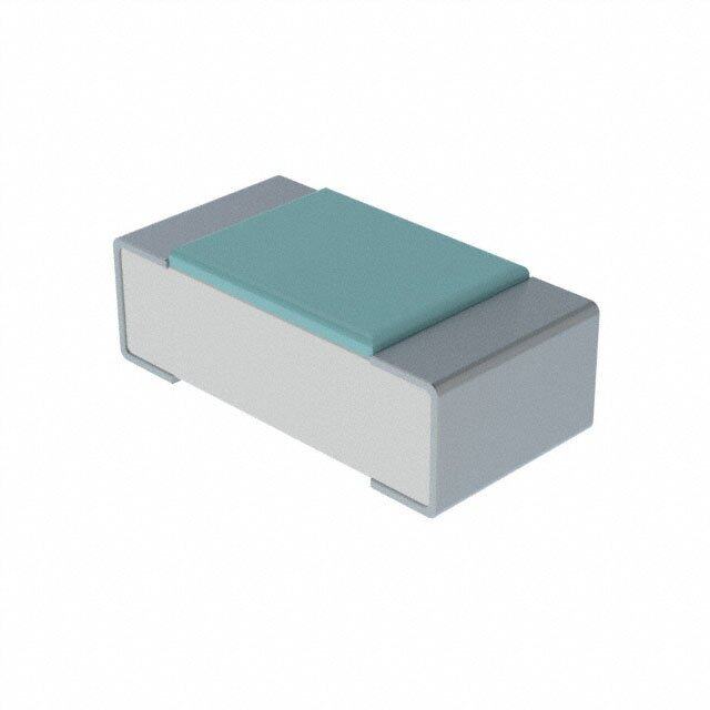
| 描述 | SMD-LED WHITE PLCC2标准LED-SMD White Clear Non-Diff |
| 产品分类 | |
| LED大小 | 3 mm x 2.8 mm x 1.75 mm |
| 品牌 | Vishay SemiconductorsVishay Semiconductor Opto Division |
| 产品手册 | |
| 产品图片 | |
| rohs | 符合RoHS无铅 / 符合限制有害物质指令(RoHS)规范要求 |
| 产品系列 | LED发射器,标准LED-SMD,Vishay Semiconductors VLMW41S1T1-5K8L-08VLM.4 |
| 数据手册 | |
| 产品型号 | VLMW41S1T1-5K8L-08VLMW41S1T1-5K8L-08 |
| 产品种类 | 标准LED-SMD |
| 光强度 | 355 mcd |
| 包装 | 带卷 (TR) |
| 商标 | Vishay Semiconductors |
| 大小/尺寸 | 3.00mm 长 x 2.80mm 宽 |
| 安装类型 | 表面贴装 |
| 封装 | Reel |
| 封装/外壳 | 2-SMD,J 形引线 |
| 封装/箱体 | PLCC-2 |
| 工厂包装数量 | 7500 |
| 显示角 | 120 deg |
| 最大工作温度 | + 100 C |
| 最小工作温度 | - 40 C |
| 标准包装 | 1,500 |
| 正向电压 | 3.3 V |
| 正向电流 | 10 mA |
| 毫烛光等级 | 180mcd ~ 355mcd |
| 波长-主 | 5500K |
| 波长-峰值 | - |
| 波长/色温 | 5500 K |
| 测试电流时的光通量 | - |
| 照明颜色 | Cool White |
| 电压-正向(Vf)(典型值) | 3.3V |
| 电流-测试 | 10mA |
| 系列 | VLMW |
| 视角 | 60° |
| 透镜样式/尺寸 | 圆形,带平顶,2.4mm |
| 透镜类型 | - |
| 透镜颜色/类型 | Yellow Emitting Phosphor |
| 颜色 | 白 |
| 高度 | 1.85mm |


- 商务部:美国ITC正式对集成电路等产品启动337调查
- 曝三星4nm工艺存在良率问题 高通将骁龙8 Gen1或转产台积电
- 太阳诱电将投资9.5亿元在常州建新厂生产MLCC 预计2023年完工
- 英特尔发布欧洲新工厂建设计划 深化IDM 2.0 战略
- 台积电先进制程称霸业界 有大客户加持明年业绩稳了
- 达到5530亿美元!SIA预计今年全球半导体销售额将创下新高
- 英特尔拟将自动驾驶子公司Mobileye上市 估值或超500亿美元
- 三星加码芯片和SET,合并消费电子和移动部门,撤换高东真等 CEO
- 三星电子宣布重大人事变动 还合并消费电子和移动部门
- 海关总署:前11个月进口集成电路产品价值2.52万亿元 增长14.8%


PDF Datasheet 数据手册内容提取
VLMW41.. www.vishay.com Vishay Semiconductors Standard SMD LED PLCC-2 FEATURES • High efficient InGaN technology • Chromaticity coordinate categorized according to CIE1931 per packing unit • Typical color temperature 5500 K • EIA and ICE standard package • Compatible with reflow, vapor phas e 19225 and wave solder processes according t o CECC 00802 and J-STD-020 DESCRIPTION • Available in 8 mm tape reel This device has been designed to meet the increasin g • Preconditioning according to JEDEC® level 2a demand for white SMD LED. • ESD-withstand voltage: up to 2 kV according to The package of the VLMW41.. is the PLCC-2. JESD22-A114-B It consists of a lead frame which is embedded in a white • AEC-Q101 qualified thermoplast. The reflector inside this package is filled with a • Material categorization: for definitions of complianc e mixture of epoxy and TAG phosphor. please see www.vishay.com/doc?99912 The TAG phosphor converts the blue emission partially t o yellow, which mixes with the remaining blue to give white. APPLICATIONS • Camera flash light PRODUCT GROUP AND PACKAGE DATA • Signal and symbol luminaire • Product group: LED • Marker lights • Package: SMD PLCC-2 • Interior and exterior automotive lighting: brake lights, tur n • Product series: standard lights, backlighting, side markers • Angle of half intensity: ± 60° • Indicator lighting PARTS TABLE LUMINOUS INTENSITY COORDINATE FORWARD VOLTAGE PART COLOR (mcd) at IF (x, y) at IF (V) at IF TECHNOLOGY (mA) (mA) (mA) MIN. TYP. MAX. MIN. TYP. MAX. MIN. TYP. MAX. 0.33, InGaN / TAG VLMW41S1T1-5K8L-08 White 180 275 355 10 - - 10 - 3.3 4.2 10 0.33 on sapphire 0.33, InGaN / TAG VLMW41S1T1-5K8L-18 White 180 275 355 10 - - 10 - 3.3 4.2 10 0.33 on sapphire 0.33, InGaN / TAG VLMW41R1T1-5K8L-08 White 112 275 355 10 - - 10 - 3.3 4.2 10 0.33 on sapphire 0.33, InGaN / TAG VLMW41R1T1-5K8L-18 White 112 275 355 10 - - 10 - 3.3 4.2 10 0.33 on sapphire 0.33, InGaN / TAG VLMW41S1T1-8K8L-08 White 180 275 355 10 - - 10 - 3.3 4.2 10 0.33 on sapphire 0.33, InGaN / TAG VLMW41S1T2-5K6L-08 White 180 275 450 10 - - 10 - 3.3 4.2 10 0.33 on sapphire 0.33, InGaN / TAG VLMW41S1T2-6K7L-08 White 180 275 450 10 - - 10 - 3.3 4.2 10 0.33 on sapphire 0.33, InGaN / TAG VLMW41S1T2-7K8L-08 White 180 275 450 10 - - 10 - 3.3 4.2 10 0.33 on sapphire Rev. 1.9, 28-May-2019 1 Document Number: 81370 For technical questions, contact: LED@vishay.com THIS DOCUMENT IS SUBJECT TO CHANGE WITHOUT NOTICE. THE PRODUCTS DESCRIBED HEREIN AND THIS DOCUMENT ARE SUBJECT TO SPECIFIC DISCLAIMERS, SET FORTH AT www.vishay.com/doc?91000
VLMW41.. www.vishay.com Vishay Semiconductors ABSOLUTE MAXIMUM RATINGS (T = 25 °C, unless otherwise specified) amb VLMW41.. PARAMETER TEST CONDITION SYMBOL VALUE UNIT DC forward current T ≤ 80 °C I 20 mA amb F Surge forward current t ≤ 10 μs I 0.1 A p FSM Power dissipation P 84 mW V Junction temperature T 110 °C j Storage temperature range T -40 to +100 °C stg Operating temperature range T -40 to +100 °C amb Thermal resistance junction-to-ambient Mounted on PC board (pad size > 16 mm2) R 360 K/W thJA OPTICAL AND ELECTRICAL CHARACTERISTICS (T = 25 °C, unless otherwise specified) amb VLMW41.., WHITE PARAMETER TEST CONDITION PART SYMBOL MIN. TYP. MAX. UNIT VLMW41R1T1 I 112 275 355 mcd V Luminous intensity I = 10 mA VLMW41S1T1 I 180 275 355 mcd F V VLMW41S1T2 I 180 275 450 mcd V Chromatically coordinate x I = 10 mA VLMW4100 x - 0.33 - acc. to CIE 1931 F Chromatically coordinate y I = 10 mA VLMW4100 y - 0.33 - acc. to CIE 1931 F Angle of half intensity I = 10 mA ϕ - ± 60 - ° F Forward voltage I = 20 mA V - 3.3 4.2 V F F Temperature coefficient of V I = 10 mA TC - -3 - mV/K F F VF Temperature coefficient of I V = 5 V TC - -0.4 - %/K V R IV Note • Not designed for reverse operation LUMINOUS INTENSITY CLASSIFICATION CROSSING TABLE LUMINOUS INTENSITY (mcd) VISHAY OSRAM GROUP OPTIONAL MIN. MAX. VLMW41.. LWT67C.. 1 112 140 R 2 140 180 1 180 224 S 2 224 280 1 280 355 T 2 355 450 Note • Luminous intensity is tested at a current pulse duration of 25 ms and an accuracy of ± 11 %. The above type numbers represent the order groups which include only a few brightness groups. Only one group will be shipped on each reel (there will be no mixing of two groups on each reel). In order to ensure availability, single brightnes s groups will not be orderable. In a similar manner for colors where wavelength groups are measured and binned, single wavelength groups will be shippe d in any one reel. In order to ensure availability, single wavelength groups will no t be orderable Rev. 1.9, 28-May-2019 2 Document Number: 81370 For technical questions, contact: LED@vishay.com THIS DOCUMENT IS SUBJECT TO CHANGE WITHOUT NOTICE. THE PRODUCTS DESCRIBED HEREIN AND THIS DOCUMENT ARE SUBJECT TO SPECIFIC DISCLAIMERS, SET FORTH AT www.vishay.com/doc?91000
VLMW41.. www.vishay.com Vishay Semiconductors CHROMATICITY COORDINATED GROUPS FOR WHITE SMD LED X Y X Y 0.291 0.268 0.330 0.330 0.285 0.279 0.330 0.347 5L 7L 0.307 0.312 0.347 0.371 0.310 0.297 0.345 0.352 0.296 0.259 0.330 0.310 0.291 0.268 0.330 0.330 5K 7K 0.310 0.297 0.338 0.342 0.313 0.284 0.352 0.344 0.310 0.297 0.345 0.352 0.307 0.312 0.347 0.371 6L 8L 0.330 0.347 0.367 0.401 0.330 0.330 0.364 0.380 0.313 0.284 0.352 0.344 0.310 0.297 0.338 0.342 6K 8K 0.330 0.330 0.364 0.380 0.330 0.310 0.360 0.357 Note • Chromaticity coordinate groups are tested at a current pulse duration of 25 ms and a tolerance of ± 0.01 TYPICAL CHARACTERISTICS (T = 25 °C, unless otherwise specified) amb 0° 10° 20° 30 30° y sit urrent (mA) 20 minous Inten 1.0 40° splacement ard C e Lu 0.9 50° ar Di I - ForwF 10 - RelativV rel 00..87 678000°°° ϕ - Angul 0 I 0 20 40 60 80 100 120 0.6 0.4 0.2 0 20913 T - Ambient Temperature (°C) 95 10319 amb Fig. 1 - Forward Current vs. Ambient Temperature Fig. 2 - Relative Luminous Intensity vs. Angular Displacement Rev. 1.9, 28-May-2019 3 Document Number: 81370 For technical questions, contact: LED@vishay.com THIS DOCUMENT IS SUBJECT TO CHANGE WITHOUT NOTICE. THE PRODUCTS DESCRIBED HEREIN AND THIS DOCUMENT ARE SUBJECT TO SPECIFIC DISCLAIMERS, SET FORTH AT www.vishay.com/doc?91000
VLMW41.. www.vishay.com Vishay Semiconductors 100 0.350 y) 90 x, 80 hift ( S 0.325 e Intensity 567000 oordinate 0.300 X v C ati 40 y Y I - Relrel 2300 hromaticit 0.275 10 C 0 f - 0.250 400 450 500 550 600 650 700 750 800 0 10 20 30 40 50 16196 λ - Wavelength (nm) 20220 I - Forward Current (mA) F Fig. 3 - Relative Intensity vs. Wavelength Fig. 6 - Chromaticity Coordinate Shift vs. Forward Current 100 1.5 sity 1.4 Current (mA) 10 uminous Inten 111...1231 ard ve L 0.9 I - ForwF I - RelatiV rel 000...678 1 0.5 2.5 3.0 3.5 4.0 4.5 -40 -20 0 20 40 60 80 100 20217 VF - Forward Voltage (V) 20914 Tamb - Ambient Temperature (°C) Fig. 4 - Forward Current vs. Forward Voltage Fig. 7 - Relative Luminous Intensity vs. Ambient Temperature 10 3.7 y nsit V) 3.6 nous Inte 1 Voltage ( 33..45 mi d u ar L w 3.3 Relative 0.1 V - ForF 3.2 I - V rel 3.1 0.01 3 1 10 100 -40 -20 0 20 40 60 80 100 20219 I - Forward Current (mA) 20915 T - Ambient Temperature (°C) F amb Fig. 5 - Relative Luminous Intensity vs. Forward Current Fig. 8 - Forward Voltage vs. Ambient Temperature Rev. 1.9, 28-May-2019 4 Document Number: 81370 For technical questions, contact: LED@vishay.com THIS DOCUMENT IS SUBJECT TO CHANGE WITHOUT NOTICE. THE PRODUCTS DESCRIBED HEREIN AND THIS DOCUMENT ARE SUBJECT TO SPECIFIC DISCLAIMERS, SET FORTH AT www.vishay.com/doc?91000
VLMW41.. www.vishay.com Vishay Semiconductors 0.40 8L 0.35 8K 7L s 7K e at 6L n 6K di 0.30 or 5L Co 5K y- 0.25 0.20 0.25 0.27 0.29 0.31 0.33 0.35 0.37 19784_3 x-Coordinates Fig. 9 - Coordinates of Colorgroups PACKAGE DIMENSIONS in millimeters 3.5 ± 0.2 1 0. ± 1.75 0.9 0.8 Pin identification technical drawings 5 according to DIN ± 0.1 C A 2.2 specifications 2.8 Dimensions in mm Ø 2.4 3 + 0.15 area covered Mounting Pad Layout with solderresist 1.2 8) 2. 4 6 ( 2. 1.6 (1.9) 4 Dimensions: reflow and vapor phase (wave soldering) A Protection Diode C 20242 Rev. 1.9, 28-May-2019 5 Document Number: 81370 For technical questions, contact: LED@vishay.com THIS DOCUMENT IS SUBJECT TO CHANGE WITHOUT NOTICE. THE PRODUCTS DESCRIBED HEREIN AND THIS DOCUMENT ARE SUBJECT TO SPECIFIC DISCLAIMERS, SET FORTH AT www.vishay.com/doc?91000
VLMW41.. www.vishay.com Vishay Semiconductors METHOD OF TAPING / POLARITY AND TAPE AND REEL SMD LED (VLM.3.../.4... - SERIES) REEL PACKAGE DIMENSION IN MILLIMETERS FOR SMD LEDS, TAPE OPTION GS18 Vishay’s LEDs in SMD packages are available in a n (= 8000 PCS.) PREFERRED antistatic 8 mm blister tape (in accordance with DIN IEC 40 (CO) 564) for automatic component insertion. 10.4 The blister tape is a plastic strip with impressed componen t 8.4 120° cavities, covered by a top tape. 4.5 3.5 13.00 Adhesive tape 2.5 12.75 1.5 62.5 60.0 Identification Label: Blister tape Vishay type group tape code production code 321 14.4max. quantity 329 18857 Fig. 12 - Reel Dimensions - GS18 Component cavity 94 8670 SOLDERING PROFILE TAPING OF VLM.3.../.4... IR Reflow Soldering Profile for Lead (Pb)-free Soldering Preconditioning acc. to JEDEC level 3 3.5 2.2 3.1 2.0 300 max. 260 °C 250 255 °C 245 °C 240 °C 5.75 5.25 4.0 C) 217 °C 33..64 87..37 3.6 erature (° 125000 max. 30 s mp max. 120 s max. 100 s e 1.85 T 100 1.65 1.6 4.1 4.1 0.25 50 max. ramp up 3 °C/s max. ramp down 6 °C/s 1.4 3.9 3.9 2.05 1.95 0 94 8668 0 50 100 150 200 250 300 Fig. 10 - Tape Dimensions in mm for PLCC-2 Time (s) 19885-1 max. 2 cycles allowed Fig. 13 - Vishay Lead (Pb)-free Reflow Soldering Profile REEL PACKAGE DIMENSION IN MILLIMETERS (according to J-STD-020) FOR SMD LEDS, TAPE OPTION GS08 (= 1500 PCS.) TTW Soldering (according to CECC00802) 300 10000 10.0 5 s 9.0 Lead temperature 120° 250 235 °C to 260 °C wSeacvoend Full line: typical Identification 43..55 21..55 1132..0705 6630..55 2nd lineemperature (°C) 112050000 1 10c30aF0 .° i 2Cr°s0C tt0 ow Ka/vse ca. 2 K/s Dprootcteeds sli nlimesit:s 1100000 1st line2nd line Label: T Vishay 2 K/s ca. 5 K/s type 50 Forced cooling group tape code production 0 10 code 180 14.4max. 0 50 100 150 200 250 quantity 178 94 8665 948626-1 Time (s) Fig. 11 - Reel Dimensions - GS08 Fig. 14 - Double Wave Soldering of Opto Devices (all packages) Rev. 1.9, 28-May-2019 6 Document Number: 81370 For technical questions, contact: LED@vishay.com THIS DOCUMENT IS SUBJECT TO CHANGE WITHOUT NOTICE. THE PRODUCTS DESCRIBED HEREIN AND THIS DOCUMENT ARE SUBJECT TO SPECIFIC DISCLAIMERS, SET FORTH AT www.vishay.com/doc?91000
VLMW41.. www.vishay.com Vishay Semiconductors BAR CODE PRODUCT LABEL (example) RECOMMENDED METHOD OF STORAGE Dry box storage is recommended as soon as the aluminu m bag has been opened to prevent moisture absorption. Th e 106 following conditions should be observed, if dry boxes ar e A H not available: VISHAY • Storage temperature 10 °C to 30 °C • Storage humidity ≤ 60 % RH max. 37 After more than 672 h under these conditions moisture content will be too high for reflow soldering. In case of moisture absorption, the devices will recover t o B C D E F G 20216 the former condition by drying under the following condition: A) Type of component 192 h at 40 °C + 5 °C / - 0 °C and < 5 % RH (dry air / B) Manufacturing plant nitrogen) or C) SEL - selection code (bin): 96 h at 60 °C + 5 °C and < 5 % RH for all device containers e.g.: R1= code for luminous intensity group or 5L= code for chrom. coordinate group 24 h at 100 °C + 5 °C not suitable for reel or tubes. D) Date code year / week An EIA JEDEC standard JESD22-A112 level 2a label is included on all dry bags. E) Day code (e.g. 4: Thursday) F) Batch no. G) Total quantity L E V E L CAUTION H) Company code M O I S T U R TEh i–sS bEaNg ScIoTnItaViEns D EVICES 2 a DRY PACKING 1. Shelf life in sealed bag 12 months at <40°C and < 90% relative humidity (RH) The reel is packed in an anti-humidity bag to protect th e 2. After this bag is opened devices that will be subjected to infrared reflow, vapor-phase reflow, or equivalent processing (peak package body temp. devices from absorbing moisture during transportation and 260°C) must be: a) Mounted within 672 hours at factory condition of < 30°C/60%RH or storage. b) Stored at <10% RH. Aluminum bag 3. Devices require baking before mounting if: a) Humidity Indicator Card is >10% when read at 23°C + 5°C or b) 2a or 2b is not met. Label 4. If baking is required, devices may be baked for: 192 hours at 40°C + 5°C/-0°C and <5%RH (dry air/nitrogen) or 96 hours at 60±5oCand <5%RH For all device containers or 24 hours at 100±5°C Not suitable for reels or tubes Bag Seal Date: ______________________________ (If blank, see bar code label) Note: LEVEL defined by EIA JEDEC Standard JESD22-A113 19786 Reel Example of JESD22-A112 level 2a label ESD PRECATION 15973 Proper storage and handling procedures should be followed FINAL PACKING to prevent ESD damage to the devices especially when they The sealed reel is packed into a cardboard box. A secondar y are removed from the antistatic shielding bag. Electrostati c cardboard box is used for shipping purposes. sensitive devices warning labels are on the packaging. VISHAY SEMICONDUCTORS STANDARD BAR CODE LABELS The Vishay Semiconductors standard bar code labels ar e printed at final packing areas. The labels are on each packing unit and contain Vishay Semiconductors specific data. Rev. 1.9, 28-May-2019 7 Document Number: 81370 For technical questions, contact: LED@vishay.com THIS DOCUMENT IS SUBJECT TO CHANGE WITHOUT NOTICE. THE PRODUCTS DESCRIBED HEREIN AND THIS DOCUMENT ARE SUBJECT TO SPECIFIC DISCLAIMERS, SET FORTH AT www.vishay.com/doc?91000
Legal Disclaimer Notice www.vishay.com Vishay Disclaimer ALL PRODUCT, PRODUCT SPECIFICATIONS AND DATA ARE SUBJECT TO CHANGE WITHOUT NOTICE TO IMPROV E RELIABILITY, FUNCTION OR DESIGN OR OTHERWISE. Vishay Intertechnology, Inc., its affiliates, agents, and employees, and all persons acting on its or their behalf (collectively, “Vishay”), disclaim any and all liability for any errors, inaccuracies or incompleteness contained in any datasheet or in any other disclosure relating to any product. Vishay makes no warranty, representation or guarantee regarding the suitability of the products for any particular purpose o r the continuing production of any product. To the maximum extent permitted by applicable law, Vishay disclaims (i) any and all liability arising out of the application or use of any product, (ii) any and all liability, including without limitation special, consequential or incidental damages, and (iii) any and all implied warranties, including warranties of fitness for particular purpose, non-infringement and merchantability. Statements regarding the suitability of products for certain types of applications are based on Vishay’s knowledge of typical requirements that are often placed on Vishay products in generic applications. Such statements are not binding statements about the suitability of products for a particular application. It is the customer’s responsibility to validate that a particular product with the properties described in the product specification is suitable for use in a particular application. Parameters provided in datasheets and / or specifications may vary in different applications and performance may vary over time. All operating parameters, including typical parameters, must be validated for each customer application by the customer’s technical experts. Product specifications do not expand or otherwise modify Vishay’s terms and conditions of purchase, including but not limited to the warranty expressed therein. Except as expressly indicated in writing, Vishay products are not designed for use in medical, life-saving, or life-sustainin g applications or for any other application in which the failure of the Vishay product could result in personal injury or death. Customers using or selling Vishay products not expressly indicated for use in such applications do so at their own risk . Please contact authorized Vishay personnel to obtain written terms and conditions regarding products designed for such applications. No license, express or implied, by estoppel or otherwise, to any intellectual property rights is granted by this documen t or by any conduct of Vishay. Product names and markings noted herein may be trademarks of their respective owners. © 2019 VISHAY INTERTECHNOLOGY, INC. ALL RIGHTS RESERVED Revision: 01-Jan-2019 1 Document Number: 91000