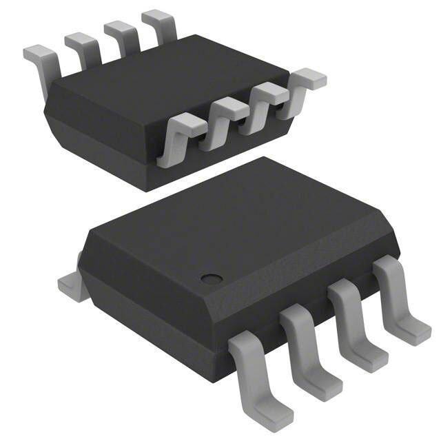
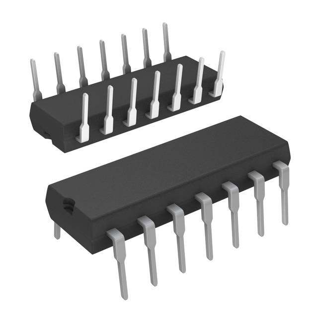
ICGOO在线商城 > 集成电路(IC) > PMIC - V/F 和 F/V 转换器 > VFC320BP
- 型号: VFC320BP
- 制造商: Texas Instruments
- 库位|库存: xxxx|xxxx
- 要求:
| 数量阶梯 | 香港交货 | 国内含税 |
| +xxxx | $xxxx | ¥xxxx |
查看当月历史价格
查看今年历史价格
VFC320BP产品简介:
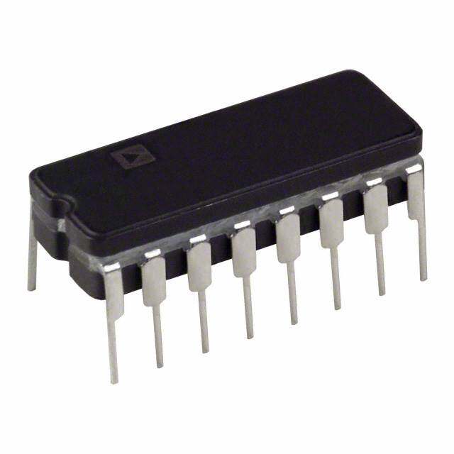
ICGOO电子元器件商城为您提供VFC320BP由Texas Instruments设计生产,在icgoo商城现货销售,并且可以通过原厂、代理商等渠道进行代购。 VFC320BP价格参考¥125.38-¥210.11。Texas InstrumentsVFC320BP封装/规格:PMIC - V/F 和 F/V 转换器, Volt to Frequency and Frequency to Volt Converter IC 1MHz ±0.1% 14-PDIP。您可以下载VFC320BP参考资料、Datasheet数据手册功能说明书,资料中有VFC320BP 详细功能的应用电路图电压和使用方法及教程。
| 参数 | 数值 |
| 产品目录 | 集成电路 (IC)半导体 |
| 描述 | IC CONVERTER V-F/F-V 14-DIP电压频率转换及频率电压转换 Vltg-to-Freq & Freq- to-Vltg Converter |
| 产品分类 | |
| 品牌 | Texas Instruments |
| 产品手册 | |
| 产品图片 |
|
| rohs | 符合RoHS无铅 / 符合限制有害物质指令(RoHS)规范要求 |
| 产品系列 | 数据转换器IC,电压频率转换及频率电压转换,Texas Instruments VFC320BP- |
| 数据手册 | |
| 产品型号 | VFC320BP |
| 产品目录页面 | |
| 产品种类 | 电压频率转换及频率电压转换 |
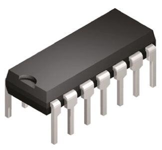
| 供应商器件封装 | 14-PDIP |
| 全标度频率 | 1000 kHz |
| 其它名称 | 296-12616-5 |
| 包装 | 管件 |
| 商标 | Texas Instruments |
| 安装类型 | 通孔 |
| 安装风格 | Through Hole |
| 封装 | Tube |
| 封装/外壳 | 14-DIP(0.300",7.62mm) |
| 封装/箱体 | PDIP-14 |
| 工厂包装数量 | 25 |
| 最大工作温度 | + 85 C |
| 最小工作温度 | - 25 C |
| 标准包装 | 25 |
| 满刻度 | ±20ppm/°C |
| 类型 | 电压到频率和频率到电压 |
| 系列 | VFC320 |
| 线性度 | ±0.1% |
| 线性误差 | +/- 0.1 % FSR |
| 频率-最大值 | 1MHz |



- 商务部:美国ITC正式对集成电路等产品启动337调查
- 曝三星4nm工艺存在良率问题 高通将骁龙8 Gen1或转产台积电
- 太阳诱电将投资9.5亿元在常州建新厂生产MLCC 预计2023年完工
- 英特尔发布欧洲新工厂建设计划 深化IDM 2.0 战略
- 台积电先进制程称霸业界 有大客户加持明年业绩稳了
- 达到5530亿美元!SIA预计今年全球半导体销售额将创下新高
- 英特尔拟将自动驾驶子公司Mobileye上市 估值或超500亿美元
- 三星加码芯片和SET,合并消费电子和移动部门,撤换高东真等 CEO
- 三星电子宣布重大人事变动 还合并消费电子和移动部门
- 海关总署:前11个月进口集成电路产品价值2.52万亿元 增长14.8%
PDF Datasheet 数据手册内容提取
VFC320 VFC320 SBVS017A – AUGUST 2001 Voltage-to-Frequency and Frequency-to-Voltage CONVERTER FEATURES DESCRIPTION (cid:1) HIGH LINEARITY: 12 to 14 bits The VFC320 monolithic voltage-to-frequency and frequency-to- ± 0.005% max at 10kHz FS voltage converter provides a simple low cost method of convert- ± 0.03% max at 100kHz FS ing analog signals into digital pulses. The digital output is an ± 0.1% typ at 1MHz FS open collector and the digital pulse train repetition rate is propor- (cid:1) V/F OR F/V CONVERSION tional to the amplitude of the analog input voltage. Output pulses (cid:1) 6-DECADE DYNAMIC RANGE are compatible with TTL, and CMOS logic families. (cid:1) GAIN DRIFT: 20ppm/°C max High linearity (0.005%, max at 10kHz FS) is achieved with relatively few external components. Two external resistors and (cid:1) OUTPUT TTL/CMOS COMPATIBLE two external capacitors are required to operate. Full scale fre- quency and input voltage are determined by a resistor in series APPLICATIONS with –In and two capacitors (one-shot timing and input amplifier integration). The other resistor is a non-critical open collector (cid:1) INEXPENSIVE A/D AND D/A CONVERTER pull-up (f to +V ). The VFC320 is available in two perfor- OUT CC (cid:1) DIGITAL PANEL METERS mance grades. The VFC320 is specified for the –25°C to +85°C, (cid:1) TWO-WIRE DIGITAL TRANSMISSION WITH range. NOISE IMMUNITY (cid:1) FM MOD/DEMOD OF TRANSDUCER SIGNALS (cid:1) PRECISION LONG TERM INTEGRATOR (cid:1) HIGH RESOLUTION OPTICAL LINK FOR ISOLATION (cid:1) AC LINE FREQUENCY MONITOR (cid:1) MOTOR SPEED MONITOR AND CONTROL +V V f CC OUT IN –In +In Comparators Fflloipp- fOUT –7.5V Ref One-shot –VCC C1 Common Please be aware that an important notice concerning availability, standard warranty, and use in critical applications of Texas Instruments semiconductor products and disclaimers thereto appears at the end of this data sheet. PRODUCTION DATA information is current as of publication date. Copyright © 1982, Texas Instruments Incorporated Products conform to specifications per the terms of Texas Instruments standard warranty. Production processing does not necessarily include testing of all parameters. www.ti.com
ELECTRICAL CHARACTERISTICS At T = +25°C and ±15VDC power supply, unless otherwise noted. A VFC320BP VFC320CP PARAMETER CONDITIONS MIN TYP MAX MIN TYP MAX UNITS V/F CONVERTER f = V /7.5 RC, Figure 4 OUT IN 1 1 INPUT TO OP AMP Voltage Range(1) Fig. 4 with e = 0 >0 Note 2 V 2 Fig. 4 with e = 0 <0 –10 V 1 Current Range(1) I = V /R +0.25 +750 ✻ ✻ µA IN IN IN Bias Current Inverting Input 4 8 ✻ ✻ nA Noninverting Input 10 30 ✻ ✻ nA Offset Voltage(3) ±0.15 ✻ mV Offset Voltage Drift ±5 ✻ µV/°C Differential Impedance 300 || 5 650 || 5 ✻ ✻ kΩ || pF Common-Mode Impedance 300 || 3 500 || 3 ✻ ✻ kΩ || pF ACCURACY Linearity Error(1) (4) (5) Fig. 4 with e = 0(6) 2 0.01Hz ≤ f ≤ 10kHz ±0.004 ±0.005 ±0.0015 ±0.002 % FSR OUT 0.1Hz ≤ f ≤ 100kHz ±0.008 ±0.030 ✻ ✻ % FSR OUT 1Hz ≤ f ≤ 1MHz ±0.1 ✻ % FSR OUT Offset Error Input Offset Voltage(3) ±15 ✻ ppm FSR Offset Drift(7) ±0.5 ✻ ppm FSR/°C Gain Error(3) ±5 ±10 ✻ ✻ % FSR Gain Drift(7) f = 10kHz 50 20 ppm FSR/°C Full Scale Drift f = 10kHz 50 20 ppm FSR/°C (Offset Drift and Gain Drift)(7)(8)(9) Power Supply Sensitivity ±V = 14VDC to 18VDC ±0.015 ✻ % FSR% CC DYNAMIC RESPONSE Full Scale Frequency C ≤ 50pF 1 ✻ MHz LOAD Dynamic Range 6 ✻ Decades Settling Time (V/F) to Specified Linearity For a Full Scale Input Step Note 10 ✻ Overload Recovery <50% Overload Note 10 ✻ OPEN COLLECTOR OUTPUT Voltage, Logic “0” I = 8mA, max 0.4 ✻ V SINK Leakage Current, Logic “1” V = 15V 0.01 1.0 ✻ ✻ µA O Voltage, Logic “1” External Pull-up Resistor Required (See Figure 4) V ✻ V PU Duty Cycle at FS For Best Linearity 25 ✻ % Fall Time I = 5mA, C = 500pF 100 ✻ ns OUT LOAD F/V CONVERTER V = 7.5 RC f , Figure 9 OUT 1 1 IN INPUT TO COMPARATOR Impedance 50 || 10 150 || 10 ✻ ✻ kΩ || pF Logic “1” +1.0 +V ✻ ✻ V CC Logic “0” –V –0.05 ✻ ✻ V CC Pulse-width Range 0.25 ✻ µs OUTPUT FROM OP AMP Voltage I = 6mA 0 to +10 ✻ V O Current V = 7VDC +10 ✻ mA O Impedance Closed-Loop 0.1 ✻ Ω Capacitive Load Without Oscillation 100 ✻ pF POWER SUPPLY Rated Voltage ±15 ✻ V Voltage Range ±13 ±20 ✻ ✻ V Quiescent Current ±6.5 ±7.5 ✻ ✻ mA TEMPERATURE RANGE Specification B and C Grades –25 +85 ✻ ✻ °C S Grade –55 +125 °C Operating B and C Grades –40 +85 ✻ ✻ °C S Grade –55 +125 °C Storage –65 +150 ✻ ✻ °C ✻ Specification the same as for VFC320BP. NOTES: (1) A 25% duty cycle at full scale (0.25mA input current) is recommended where possible to achieve best linearity. (2) Determined by R and full scale current range IN constraints. (3) Adjustable to zero. See Offset and Gain Adjustment section. (4) Linearity error at any operating frequency is defined as the deviation from a straight line drawn between the full scale frequency and 0.1% of full scale frequency. See Discussion of Specifications section. (5) When offset and gain errors are nulled, at an operating temperature, the linearity error determines the final accuracy. (6) For e = 0 typical linearity errors are: 0.01% at 10kHz, 0.2% at 100kHz, 0.1% at 1MHz. (7) Exclusive of external components’ drift. 1 (8) FSR = Full Scale Range (corresponds to full scale and full scale input voltage.) (9) Positive drift is defined to be increasing frequency with increasing temperature. (10) One pulse of new frequency plus 50ns typical. VFC320 2 SBVS017A
ABSOLUTE MAXIMUM RATINGS ELECTROSTATIC Supply Voltage...................................................................................±20V DISCHARGE SENSITIVITY Output Sink Current at f ...............................................................50mA OUT Output Current at V ...................................................................+20mA Input Voltage, –InpuOtU..T........................................................................±V This integrated circuit can be damaged by ESD. Texas Instru- CC Input Voltage, +Input..........................................................................±V ments recommends that all integrated circuits be handled with CC Storage Temperature Range..........................................–65°C to +150°C appropriate precautions. Failure to observe proper handling Lead Temperature (soldering, 10s)...............................................+300°C and installation procedures can cause damage. ESD damage can range from subtle performance degradation to complete device failure. Precision integrated circuits may be more susceptible to damage because very small parametric changes could cause the device not to meet its published specifications. PACKAGE/ORDERING INFORMATION PACKAGE SPECIFIED DRAWING PACKAGE TEMPERATURE PACKAGE ORDERING TRANSPORT PRODUCT PACKAGE NUMBER DESIGNATOR RANGE MARKING NUMBER(1) MEDIA VFC320BP DIP-14 010 N –40°C to +85°C VFC320CP DIP-14 010 N –40°C to +85°C NOTE: (1) Models with a slash (/) are available only in Tape and Reel in the quantities indicated (e.g., /2K5 indicates 2500 devices per reel). Ordering 2500 pieces of “VFC320BP/2K5” will get a single 2500-piece Tape and Reel. PIN CONFIGURATION Top View DIP –In 1 14 +In NC 2 13 V OUT Input NC 3 Amp 12 +VCC –V 4 11 Common CC h c One-Shot 5 wit 10 Comparator Capacitor S Input NC 6 One- 9 NC shot f 7 8 NC OUT VFC320 3 SBVS017A
DISCUSSION OF FREQUENCY STABILITY VS TEMPERATURE SPECIFICATIONS The full scale frequency drift of the VFC320 versus tem- perature is expressed as parts per million of full scale range LINEARITY per °C. As shown in Figure 3, the drift increases above 10kHz. To determine the total accuracy drift over tempera- Linearity is the maximum deviation of the actual transfer ture, the drift coefficients of external components (espe- function from a straight line drawn between the end points cially R and C ) must be added to the drift of the VFC320. (100% full scale input or frequency and 0.1% of full scale 1 1 called zero.) Linearity is the most demanding measure of voltage-to-frequency converter performance, and is a func- tion of the full scale frequency. Refer to Figure 1 to deter- 1000 mine typical linearity error for your application. Once the full scale frequency is chosen, the linearity is a function of Drift operating frequency as it varies between zero and full scale. p mC) Elinxeaamriptlye sis faocrh 1ie0vkeHdz a tf ulollw secra glea ianrse (s∆hfown/ ∆in Fi)g wurieth 2 o. pBereas-t ale TeFSR/° 100 tTiohne ahsi gchlo slien etoa rtihtye cohf otsheen fVuFllC s3c2al0e mfOrUeaTqkueesV nItcNhye ads epvoicssei balne al Full Sc(ppm of B and S Grades c excellent choice for use as the front end of Analog-to-Digital Typi C Grade (A/D) converters with 12- to 14-bit resolution, and for highly accurate transfer of analog data over long lines in 10 noisy environments (2-wire digital transmission.) 1k 10k 100k 1M Full Scale Frequency (Hz) Figure 3. Full Scale Drift vs Full Scale Frequency. 0.10 R) S RESPONSE F % of Response of the VFC320 to changes in input signal level is or ( specified for a full scale step, and is 50ns plus 1 pulse of the Err 0.01 new frequency. For a 10V input signal step with the VFC320 y arit operating at 100kHz full scale, the settling time to within ne ±0.01% of full scale is 10µs. Li cal TA = +25°C pi y T DFS = 0.25 THEORY OF OPERATION 0.001 1k 10k 100k 1M The VFC320 monolithic voltage-to-frequency converter pro- Full Scale Frequency (Hz) vides a digital pulse train output whose repetition rate is directly proportional to the analog input voltage. The circuit Figure 1. Linearity Error vs Full Scale Frequency. shown in Figure 4 is composed of an input amplifier, two Figure comparators and a flip-flop (forming a on-shot), two switched current sinks, and an open collector output transistor stage. 0.003 Essentially the input amplifier acts as an integrator that f = 10kHz FSR) 0.002 FULL SCALE B Grade produces a two-part ramp. The first part is a function of the of input voltage, and the second part is dependent on the input orf (% 0.001 C Grade vapopltlaigede aatn Vd cu, rar ecnutr rseinntk w. Will hfleonw a t hproosuitgivhe t hien pinupt uvto rletsaigseto irs, y jErr 0 causing the INvoltage at VOUT to ramp down toward zero, Linearit –0.001 astcacnotr cduinrrge ntot sdinVk/ dist d=i sVabINle/Rd 1bCy1 t.h De uswrinitgc ht.h Niso ttiem, teh itsh ep ecroiond- pical –0.002 is only dependent on VIN and the integrating components. y T Typical, T = +25°C When the ramp reaches a voltage close to zero, comparator A –0.003 A sets the flip-flop. This closes the current sink switches as 0 1k 2k 3k 4k 5k 6k 7k 8k 9k 10k well as changing f from logic 0 to logic 1. The ramp now Operating Frequency (Hz) OUT begins to ramp up, and 1mA charges through C until V = 1 C1 –7.5V. Note this ramp period is dependent on the 1mA Figure 2. Linearity Error vs Operating Frequency. current sink, connected to the negative input of the op amp, Figure as well as the input voltage. At this –7.5V threshold point C , comparator B resets the flip-flop, and the ramp voltage 1 VFC320 4 SBVS017A
C 2 Integrating +VCC (5V+ VtoP U1L5LV-U TP y(VpiPcUa)lly) Input Resistor Capacitor VOUT 13 10 fIN 12 R 1 1 Pull-up e IIN 14 IAnmpupt A Resitor R2 1 Flip- 7 I Comparators B flop –7.5V Q fOUT IA CuCrroennst tSanintks Ref B 1 e2 (1mA) f = VIN OUT 7.5 R C 1 1 Switch One-shot 4 5 11 Common –V C1 One-shot CC Capacitor V IN: For Postive Input Voltages use e, short e. 1 2 For Negative Input Voltages use e, short e. 2 1 For Differental Input Voltages use e e. 1 and 2 FIGURE 4. Functional Block Diagram of the VFC320. begins to ramp down again before the input amplifier has a In the time t + t the integrator capacitor C charges and 1 2 2 chance to saturate. In effect the comparators and flip-flop discharges but the net voltage change is zero. form a one-shot whose period is determined by the internal Thus ∆Q = 0 = I t + (I – I ) t (2) IN 1 IN A 2 reference and a 1mA current sink plus the external capacitor, So that I (t + t ) = I t (3) C . After the one-shot resets, f changes back to logic 0 IN 1 2 A 2 1 OUT and the cycle begins again. 1 VIN But since t + t = and I = (4), (5) The transfer function for the VFC320 is derived for the 1 2 f IN R OUT 1 circuit shown in Figure 4. Detailed waveforms are shown in V Figure 5. IN f = (6) OUT I R R 1 A 2 2 f = (1) OUT t + t In the time t , I charges the one-shot capacitor C until its 1 2 1 B 1 voltage reaches –7.5V and trips comparator B. C 7.5 Thus t = IN (7) 0V 2 I ot B e-shVC1 V I (8) On Using(7)in(6)yieldf = IN • B OUT 7.5R C I 1 1 A –7.5V Since I = I the result is A B V or Output OUT ∆VOUT fOUT = 7.5 RIN1 C1 (9) egratV Since the integrating capacitor, C2, affects both the rising Int t1 and falling segments of the ramp voltage, its tolerance and t2 temperature coefficient do not affect the output frequency. It should, however, have a leakage current that is small com- ut p pared to I , since this parameter will add directly to the gain Out OUT error of tIhNe VFC. C , which controls the one-shot period, C f 1 VF should be very precise since its tolerance and temperature coefficient add directly to the errors in the transfer function. FIGURE 5. Integrator and VFC Output Timing. VFC320 5 SBVS017A
The operation of the VFC320 as a highly linear frequency- to-voltage converter, follows the same theory of operation as C 2 Integrator Capacitor the voltage-to-frequency converter. e and e are shorted and Gain Adjustment 1 2 F is disconnected from V . F is then driven with a I IN OUT IN IN V signal which is sufficient to trigger comparator A. The one- IN 1 14 shot period will then be determined by C as before, but the R R 1 1 3 cycle repetition frequency will be dictated by the digital NC 2 13 +15V input at F . Input IN R R4 NC 3 Amp 12 +VCC(1) 5 DUTY CYCLE –15V –VCC(1) 4 ch 11 The duty cycle (D) of the VFC is the ratio of the one-shot Offset Adj. 5 wit 10 S C period (t ) or pulse width, PW, to the total VFC period (t + One-shot 1 2 1 Capacitor NC 6 One- 9 NC t ). For the VFC320, t is fixed and t + t varies as the input 2 2 1 2 shot voltage. Thus the duty cycle, D, is a function of the input +VPU 7 8 NC voltage. Of particular interest is the duty cycle at full scale R 2 f frequency, D , which occurs at full scale input. D is a user OUT Pin numbers in squares FS FS determined parameter which affects linearity. NOTE: (1) Bypass with 0.01µF refer to DIP package. t D = 2 =PW•f FIGURE 7. Connection Diagram for V/F Conversion, FS t +t FS 1 2 Negative Input Voltages. Best linearity is achieved when D is 25%. By reducing FS equations (7) and (9) it can be shown that EXTERNAL COMPONENT SELECTION V max / R I max In general, the design sequence consists of: (1) choosing D = I N 1 = IN FS f , (2) choosing the duty cycle at full scale (D = 0.25 1mA 1mA MAX FS typically), (3) determining the input resistor, R (Figure 4), Thus D = 0.25 corresponds to I max = 0.25mA. 1 FS IN (4) calculating the one-shot capacitor, C , (5) selecting the 1 integrator capacitor C , and (6) selecting the output pull-up 2 resistor, R . INSTALLATION AND 2 OPERATING INSTRUCTIONS Input Resistors R and R 1 3 VOLTAGE-TO-FREQUENCY CONVERSION The input resistance (R and R in Figures 6 and 7) is 1 3 calculated to set the desired input current at full scale input The VCF320 can be connected to operate as a V/F converter voltage. This is normally 0.25mA to provide a 25% duty that will accept either positive or negative input voltages, or cycle at full scale input and output. Values other than D = an input current. Refer to Figures 6 and 7. FS 0.25 may be used but linearity will be affected. The nominal value is R is 1 V max C IN 2 Integrator Capacitor R = Gain Adjustment 1 0.25mA (10) I V IN If gain trimming is to be done, the nominal value is reduced IN 1 14 by the tolerance of C and the desired trim range. R should 1 1 R R 3 1 have a very-low temperature coefficient since its drift adds NC 2 13 +15V directly to the errors in the transfer function. Input R R4 NC 3 Amp 12 +VCC(1) 5 Offset A–1d5j.V –VCC(1) 45 witch 1110 OThnies -cSaphaocti toCra dpeatecrimtoinre, sC th1e duration of the one-shot pulse. C S From equation (9) the nominal value is One-shot 1 capacitor NC 6 One- 9 NC V IN shot C = +VPU 7 8 NC 1 NOM 7.5 R1 fOUT (11) R 2 f For the usual 25% duty at f = V /R = 0.25mA there is OUT Pin numbers in squares MAX IN 1 approximately 15pF of residual capacitance so that the NOTE: (1) Bypass with 0.01µF refer to DIP package. design value is FIGURE 6. Connection Diagram for V/F Conversion, 33 • 106 C (pF) = – 15 Positive Input Voltages. 1 f FS (12) VFC320 6 SBVS017A
where f is the full scale output frequency in Hz. The OFFSET AND GAIN ADJUSTMENT PROCEDURES FS temperature drift of C is critical since it will add directly to 1 To null errors to zero, follow this procedure: the errors of the transfer function. An NPO ceramic type is 1. Apply an input voltage that should produce an output recommended. Every effort should be made to minimize frequency of 0.001 • full scale. stray capacitance associated with C . It should be mounted 1 2. Adjust R for proper output. as close to the VFC320 as possible. Figure 8 shows pulse 5 3. Apply the full scale input voltage. width and full scale frequency for various values of C at 1 4. Adjust R for proper output. D = 25%. 3 FS 5. Repeat stems 1 through 4. If nulling is unnecessary for the application, delete R and 10,000 106 4 R , and replace R with a short circuit. 5 3 Full Scale Frequency Pulse Width (µs) 1100000 Pulse Width 110054 Scale Frequency (Hz) PTosTufhhO peeFpW sSpleioR Eeswsu/R %pwe prS h lmsiiUeucashPpx psP.ah lryLToe uY orsel tdjmaCe bbcOaletiei nNbo ttynSoap i IrnwaDa stiE±sitohe0R di.on0 Aaf 1 ±sTt5 1hcI%O%leo NVs caeSoFr aenCs vr 3pee2orc0sosi smoiisnbm ,l0 ee.p 0tnoo1dw 5teh%eder. 10 103 Full converter with 0.01µF capacitors. Internal circuitry causes some current to flow in the common 1 102 101 102 103 104 105 connection (pin 11 on DIP package). Current flowing into the f pin (logic sink current) will also contribute to this Capacitance C1(pF) OUT current. It is advisable to separate this common lead ground FIGURE 8. Output Pulse Width (D = 0.25) and Full Scale from the analog ground associated with the integrator input FS Frequency vs External One-shot Capacitance. to avoid errors produced by these currents flowing through any ground return impedance. Integrating Capacitor, C 2 DESIGN EXAMPLE Since C does not occur in the V/F transfer function equation 2 (9), its tolerance and temperature stability are not important; Given a full scale input of +10V, select the values of R , R , 1 2 however, leakage current in C causes a gain error. A R , C , and C for a 25% duty cycle at 100kHz maximum 2 3 1 2 ceramic type is sufficient for most applications. The value of operation into one TTL load. See Figure 6. C determines the amplitude of V . Input amplifier satu- 2 OUT ration, noise levels for the comparators and slew rate limit- Selecting C (D = 0.25) 1 FS ing of the integrator determine a range of acceptable values, C = [(33 • 106)/f ] – 15 [(66 • 106)/f ] – 15 100/f ; if f ≤ 100kHz (13) 1 MAX MAX FS FS if D = 0.5 C (µF) = 0.001; if 100kHz < f ≤ 500kHz FS 2 FS = [(33 • 106)/100kHz] – 15 0.0005; if f > 500kHz FS = 315pF Choose a 300pF NPO ceramic capacitor with 1% to 10% Output Pull Up Resistor R 2 tolerance. The open collector output can sink up to 8mA and still be TTL-compatible. Select R according to this equation: 2 Selecting R and R (D = 0.25) R min (Ω) V /(8mA – I ) 1 3 RS 2 PULLUP LOAD R + R = V max/0.25mA V max/0.5mA 1 3 IN IN A 10% carbon film resistor is suitable for use as R . 2 if D = 0.5 FS = 10V/0.25mA Trimming Components R , R , R 3 4 5 = 40kΩ R nulls the offset voltage of the input amplifier. It should 5 have a series resistance between 10kΩ and 100kΩ and a Choose 32.4kΩ metal film resistor with 1% tolerance and temperature coefficient less than 100ppm/°C. R can be a R = 10kΩ cermet potentiometer. 4 3 10% carbon film resistor with a value of 10MΩ. R nulls the gain errors of the converter and compensates for Selecting C 3 2 initial tolerances of R and C . Its total resistance should be 1 1 C = 102/F 2 MAX at least 20% of R , if R is selected 10% low. Its temperature 1 1 = 102/100kHz coefficient should be no greater than five times that of R to 1 maintain a low drift of the R - R series combination. = 0.001µF 3 1 Choose a 0.001µF capacitor with ±5% tolerance. VFC320 7 SBVS017A
Selecting R pin 10 should be biased closer to zero to insure that the input 2 signal at pin 10 crosses the zero threshold. R = V /(8mA – I ) 2 PULLUP LOAD Errors are nulled using 0.001 • full scale frequency to null =5V/(8mA – 1.6mA), one TTL-load = 1.6mA offset, and full scale frequency to null the gain error. The =781Ω procedure is given on this page. Use equations from V/F Choose a 750Ω 1/4-watt carbon compensation resistor with calculations to find R , R , R , C and C . 1 3 4 1 2 ±5% tolerance. TYPICAL APPLICATIONS FREQUENCY-TO-VOLTAGE CONVERSION To operate the VFC320 as a frequency-to-voltage converter, Excellent linearity, wide dynamic range, and compatible connect the unit as shown in Figure 9. To interface with TTL, DTL, and CMOS digital output make the VFC320 TTL-logic, the input should be coupled through a capacitor, ideal for a variety of VFC applications. High accuracy and the input to pin 10 biased near +2.5V. The converter will allows the VFC320 to be used where absolute or exact detect the falling edges of the input pulse train as the voltage readings must be made. It is also suitable for systems at pin 10 crosses zero. Choose C to make t = 0.1t (see requiring high resolution up to 14 bits 3 Figure 9). For input signals with amplitudes less than 5V, Figures 10-14 show typical applications of the VFC320. R 1 R 3 C 2 Integrator Capacitor +15V R 4 R5 1 14 T NC 2 13 –15V Input +VCC(1) VOUT NC 3 Amp 12 12kΩ +1V –V (1) 4 11 R 0V CC h 6 C COanpea-schitootr 5 Switc 10 2.5V 3 fIN (t) C 1 0.001µF NC 6 One- 9 NC R 7 shot 2.2kΩ f 7 8 NC OUT Pin numbers in squares F = 100kHz NOTE: (1) Bypass with 0.01µF refer to DIP package. FS FIGURE 9. Connection Diagram for F/V Conversion. + f V OUT Sensor INA101 IN VFC320 Counter Parallel – High Noise Data Computer Instrumentation Immunity Amp Clock FIGURE 10. Inexpensive A/D with Two-Wire Digital Transmission Over Twisted Pair. e1 VIN Differential e VFC320 fOUT BDC Input 2 Counter Clock Driver/Display FIGURE 11. Inexpensive Digital Panel Meter. VFC320 8 SBVS017A
fIN VFC320 VOUT Analog F/V Output Digital Output Transducer INA101 VIN VFVC/3F20 fOUT FOT FOR CoBuCnDter Precision DC Instrumentation 0.005% Linearity Driver levels down to Clock Amp 10mV full scale Display FIGURE 12. Remote Transducer Readout via Fiber Optic Link (Analog and Digital Output). +15V R1 R2 R3 Gain Adjust 0.01µF 11kΩ 100kΩ 40.2kΩ Integrator Current +10V to –10V 30kΩ IN41D541 R C2 0.01µF 1Input 8 7 +15V6 1 12 10 2kΩ 3510B 8.66k4Ω VIN– VFC320 fOUT e + 1 10V 20kΩ 20kΩ 13 Bipolar VFC320 Input Q1 REF101 5 11 7 2N2222 C1 14 5 0 to Sign Bit 3270pF 10kHz Out 4 3 Output 4.7kΩ 4.7kΩ 3300pF –15V +V CC FIGURE 13. Bipolar input is accomplished by offsetting the FIGURE 14. Absolute value circuit with the VFC320. Op input to the VFC with a reference voltage. amp, D and Q (its base-emitter junction 1 1 Accurately matched resistors in the REF101 functioning as a diode) provide full-wave provide a stable half-scale output frequency at rectification of bipolar input voltages. VFC zero volts input. output frequency is proportional to | e |. The 1 sign bit output provides indication of the input polarity. VFC320 9 SBVS017A
PACKAGE DRAWING MPDI002B – JANUARY 1995 – REVISED FEBRUARY 2000 N (R-PDIP-T**) PLASTIC DUAL-IN-LINE PACKAGE 16 PINS SHOWN PINS ** 14 16 18 20 DIM 0.775 0.775 0.920 0.975 A A MAX (19,69) (19,69) (23,37) (24,77) 16 9 0.745 0.745 0.850 0.940 A MIN (18,92) (18,92) (21,59) (23,88) 0.260 (6,60) 0.240 (6,10) 1 8 0.070 (1,78) MAX 0.325 (8,26) 0.035 (0,89) MAX 0.020 (0,51) MIN 0.300 (7,62) 0.015 (0,38) 0.200 (5,08) MAX Gauge Plane Seating Plane 0.125 (3,18) MIN 0.010 (0,25) NOM 0.100 (2,54) 0.430 (10,92) MAX 0.021 (0,53) 0.010 (0,25) M 0.015 (0,38) 14/18 PIN ONLY 4040049/D 02/00 NOTES: A. All linear dimensions are in inches (millimeters). B. This drawing is subject to change without notice. C. Falls within JEDEC MS-001 (20-pin package is shorter than MS-001). VFC320 10 SBVS017A
IMPORTANTNOTICE TexasInstrumentsIncorporatedanditssubsidiaries(TI)reservetherighttomakecorrections,modifications,enhancements,improvements, andotherchangestoitsproductsandservicesatanytimeandtodiscontinueanyproductorservicewithoutnotice.Customersshould obtainthelatestrelevantinformationbeforeplacingordersandshouldverifythatsuchinformationiscurrentandcomplete.Allproductsare soldsubjecttoTI’stermsandconditionsofsalesuppliedatthetimeoforderacknowledgment. TIwarrantsperformanceofitshardwareproductstothespecificationsapplicableatthetimeofsaleinaccordancewithTI’sstandard warranty.TestingandotherqualitycontroltechniquesareusedtotheextentTIdeemsnecessarytosupportthiswarranty.Exceptwhere mandatedbygovernmentrequirements,testingofallparametersofeachproductisnotnecessarilyperformed. TIassumesnoliabilityforapplicationsassistanceorcustomerproductdesign.Customersareresponsiblefortheirproductsand applicationsusingTIcomponents.Tominimizetherisksassociatedwithcustomerproductsandapplications,customersshouldprovide adequatedesignandoperatingsafeguards. TIdoesnotwarrantorrepresentthatanylicense,eitherexpressorimplied,isgrantedunderanyTIpatentright,copyright,maskworkright, orotherTIintellectualpropertyrightrelatingtoanycombination,machine,orprocessinwhichTIproductsorservicesareused.Information publishedbyTIregardingthird-partyproductsorservicesdoesnotconstitutealicensefromTItousesuchproductsorservicesora warrantyorendorsementthereof.Useofsuchinformationmayrequirealicensefromathirdpartyunderthepatentsorotherintellectual propertyofthethirdparty,oralicensefromTIunderthepatentsorotherintellectualpropertyofTI. ReproductionofTIinformationinTIdatabooksordatasheetsispermissibleonlyifreproductioniswithoutalterationandisaccompanied byallassociatedwarranties,conditions,limitations,andnotices.Reproductionofthisinformationwithalterationisanunfairanddeceptive businesspractice.TIisnotresponsibleorliableforsuchaltereddocumentation.Informationofthirdpartiesmaybesubjecttoadditional restrictions. ResaleofTIproductsorserviceswithstatementsdifferentfromorbeyondtheparametersstatedbyTIforthatproductorservicevoidsall expressandanyimpliedwarrantiesfortheassociatedTIproductorserviceandisanunfairanddeceptivebusinesspractice.TIisnot responsibleorliableforanysuchstatements. TIproductsarenotauthorizedforuseinsafety-criticalapplications(suchaslifesupport)whereafailureoftheTIproductwouldreasonably beexpectedtocauseseverepersonalinjuryordeath,unlessofficersofthepartieshaveexecutedanagreementspecificallygoverning suchuse.Buyersrepresentthattheyhaveallnecessaryexpertiseinthesafetyandregulatoryramificationsoftheirapplications,and acknowledgeandagreethattheyaresolelyresponsibleforalllegal,regulatoryandsafety-relatedrequirementsconcerningtheirproducts andanyuseofTIproductsinsuchsafety-criticalapplications,notwithstandinganyapplications-relatedinformationorsupportthatmaybe providedbyTI.Further,BuyersmustfullyindemnifyTIanditsrepresentativesagainstanydamagesarisingoutoftheuseofTIproductsin suchsafety-criticalapplications. TIproductsareneitherdesignednorintendedforuseinmilitary/aerospaceapplicationsorenvironmentsunlesstheTIproductsare specificallydesignatedbyTIasmilitary-gradeor"enhancedplastic."OnlyproductsdesignatedbyTIasmilitary-grademeetmilitary specifications.BuyersacknowledgeandagreethatanysuchuseofTIproductswhichTIhasnotdesignatedasmilitary-gradeissolelyat theBuyer'srisk,andthattheyaresolelyresponsibleforcompliancewithalllegalandregulatoryrequirementsinconnectionwithsuchuse. TIproductsareneitherdesignednorintendedforuseinautomotiveapplicationsorenvironmentsunlessthespecificTIproductsare designatedbyTIascompliantwithISO/TS16949requirements.Buyersacknowledgeandagreethat,iftheyuseanynon-designated productsinautomotiveapplications,TIwillnotberesponsibleforanyfailuretomeetsuchrequirements. FollowingareURLswhereyoucanobtaininformationonotherTexasInstrumentsproductsandapplicationsolutions: Products Applications Amplifiers amplifier.ti.com Audio www.ti.com/audio DataConverters dataconverter.ti.com Automotive www.ti.com/automotive DSP dsp.ti.com Broadband www.ti.com/broadband ClocksandTimers www.ti.com/clocks DigitalControl www.ti.com/digitalcontrol Interface interface.ti.com Medical www.ti.com/medical Logic logic.ti.com Military www.ti.com/military PowerMgmt power.ti.com OpticalNetworking www.ti.com/opticalnetwork Microcontrollers microcontroller.ti.com Security www.ti.com/security RFID www.ti-rfid.com Telephony www.ti.com/telephony RF/IFandZigBee®Solutions www.ti.com/lprf Video&Imaging www.ti.com/video Wireless www.ti.com/wireless MailingAddress:TexasInstruments,PostOfficeBox655303,Dallas,Texas75265 Copyright©2008,TexasInstrumentsIncorporated
 Datasheet下载

