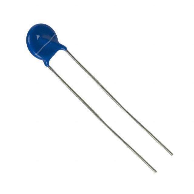
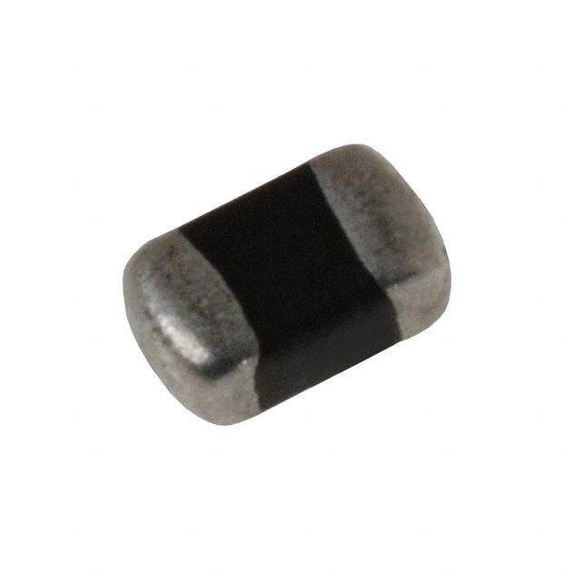
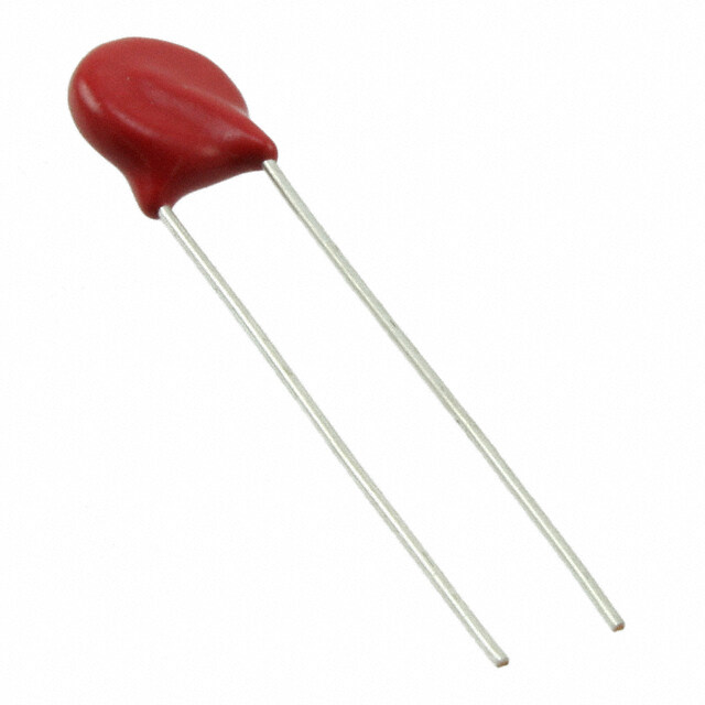
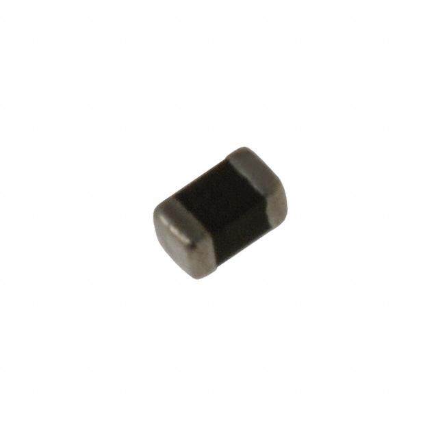
ICGOO在线商城 > 电路保护 > TVS - 变阻器,MOV > VC120626D580DP
- 型号: VC120626D580DP
- 制造商: AVX
- 库位|库存: xxxx|xxxx
- 要求:
| 数量阶梯 | 香港交货 | 国内含税 |
| +xxxx | $xxxx | ¥xxxx |
查看当月历史价格
查看今年历史价格
VC120626D580DP产品简介:
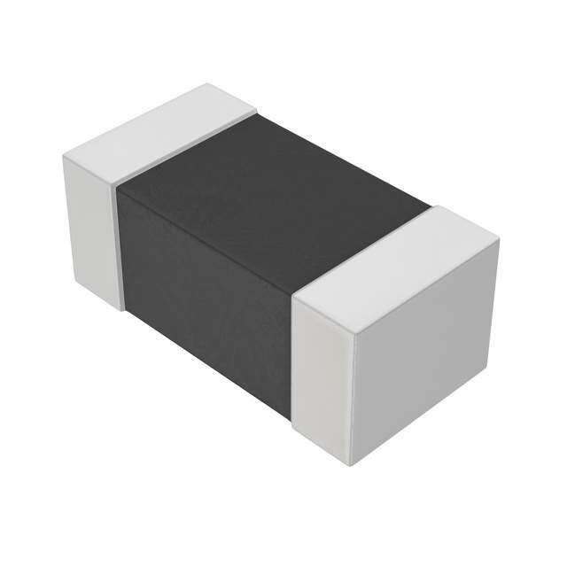
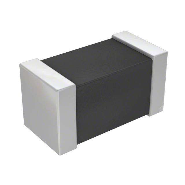
ICGOO电子元器件商城为您提供VC120626D580DP由AVX设计生产,在icgoo商城现货销售,并且可以通过原厂、代理商等渠道进行代购。 VC120626D580DP价格参考。AVXVC120626D580DP封装/规格:TVS - 变阻器,MOV, 34.5V 120A Varistor 1 Circuit Surface Mount, MLCV 1206 (3216 Metric)。您可以下载VC120626D580DP参考资料、Datasheet数据手册功能说明书,资料中有VC120626D580DP 详细功能的应用电路图电压和使用方法及教程。
| 参数 | 数值 |
| 产品目录 | |
| 描述 | VARISTOR 31.05V 120A 1206压敏电阻 26V 0.4J Energy |
| 产品分类 | |
| 品牌 | AVX |
| 产品手册 | |
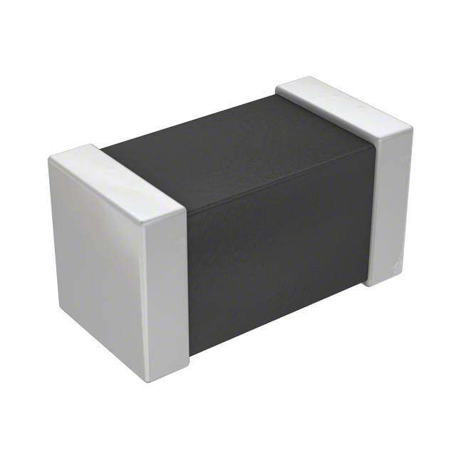
| 产品图片 |
|
| rohs | 符合RoHS无铅 / 符合限制有害物质指令(RoHS)规范要求 |
| 产品系列 | AVX VC120626D580DPTransGuard® |
| 数据手册 | |
| 产品型号 | VC120626D580DP |
| PCN设计/规格 | |
| 产品 | MLV |
| 产品培训模块 | http://www.digikey.cn/PTM/IndividualPTM.page?site=cn&lang=zhs&ptm=4641http://www.digikey.cn/PTM/IndividualPTM.page?site=cn&lang=zhs&ptm=4493http://www.digikey.cn/PTM/IndividualPTM.page?site=cn&lang=zhs&ptm=14046http://www.digikey.cn/PTM/IndividualPTM.page?site=cn&lang=zhs&ptm=19144http://www.digikey.cn/PTM/IndividualPTM.page?site=cn&lang=zhs&ptm=21795 |
| 产品目录绘图 |
|
| 产品目录页面 | |
| 产品种类 | 压敏电阻 |
| 其它名称 | 478-2522-2 |
| 包装 | 剪切带 (CT) |
| 变阻器电压 | 31.05V |
| 商标 | AVX |
| 商标名 | TransGuard |
| 外壳代码-in | 1206 |
| 外壳代码-mm | 3216 |
| 外壳宽度 | 1.6 mm |
| 安装 | SMD/SMT |
| 宽度 | 1.6 mm |
| 封装 | Reel |
| 封装/外壳 | 1206(3216 公制) |
| 封装/箱体 | 1206 (3216 metric) |
| 尺寸 | 1.6 mm W x 3.2 mm L x 1.02 mm H |
| 峰值浪涌电流 | 120 A |
| 工作温度范围 | - 55 C to + 125 C |
| 工厂包装数量 | 1000 |
| 最大AC电压 | 18VAC |
| 最大DC电压 | 26VDC |
| 标准包装 | 1,000 |
| 浪涌能量额定值 | 0.4 J |
| 电压额定值AC | 18 V |
| 电压额定值DC | 26 V |
| 电容 | 500 pF |
| 电流-浪涌 | 120A |
| 电路数 | 1 |
| 端接类型 | SMD/SMT |
| 系列 | VC |
| 能量 | 0.40J |
| 钳位电压 | 60 V |

PDF Datasheet 数据手册内容提取
TransGuard® AVX Multilayer Ceramic Transient Voltage Suppressors GENERAL DESCRIPTION TransGuard® multilayer varistors are zinc oxide (ZnO) based ceramic semiconductor devices with non-linear voltage-current characteristics (bi-directional) similar to back- to-back zener diodes. They have the added advantage of greater current and energy handling capabilities as well as EMI/RFI attenuation. The increasing use of electronics technologies in all areas require reliable protection against transient voltages that could damage the electronics circuitry as well as EMI/RFI attenuation to prevent signal distortion and to meet regulatory requirements. AVX TransGuard components help achieve both functions with single component. GENERAL FEATURES APPLICATIONS CHARACTERISTICS • Bi-Directional protection • IC Protection • Smart Grid • Very fast response to ESD strikes • Micro Controllers • Telecom • Operating Temperature: • Multi-strike capability • Relays • LED Lights -55°C to +125°C • High Reliability • I/O Ports • Cameras • Working Voltage: 3.3 - 85Vdc • EMI/RFI Filtering • Keyboard Protection • Base Stations • Case Size: 0402 - 1812 • Wide range of components • Portable devices • Motion detector • Energy: 0.05 - 4.2J • Industrial Controllers • Alarms • Peak Current: 20 - 2000A • Automation • and more HOW TO ORDER VC 1206 18 D 400 R P Varistor Case Working Energy Clamping Packaging Termination Chip Size Voltage Rating Voltage D = 7" (1000)* P = Ni/Sn plated VC = Varistor Chip 0402 03 = 3.3Vdc 31 = 31Vdc X = 0.05J K = 0.6J 100 = 12V 580 = 60V R = 7" (4000 or VG = Varistor Glass 0603 05 = 5.6Vdc 38 = 38Vdc A = 0.1J M = 1.0J 150 = 18V 620 = 67V 2000)* 0805 09 = 9Vdc 42 = 42Vdc B = 0.2J N = 1.1J 200 = 22V 650 = 67V T = 13" (10,000)* 1206 12 = 12Vdc 45 = 45Vdc C = 0.3J P = 2.5-3.7J 250 = 27V 770 = 77V W = 7" (10,000)** 1210 14 = 14Vdc 48 = 48Vdc D = 0.4J R = 1.7J 300 = 32V 800 = 80V 1812 16 = 16Vdc 56 = 56Vdc E = 0.5J L = 0.8J 380 = 38V 900 = 90V *Not available for 0402 2220 18 = 18Vdc 60 = 60Vdc F = 0.7J S = 1.9-2.0J 390 = 42V 101 = 100V **Only available for 0402 3220 22 = 22Vdc 65 = 65Vdc G = 0.9J U = 4.0-5.0J 400 = 42V 111 = 110V 26 = 26Vdc 85 = 85Vdc H = 1.2J W = 5.1-6.0J 440 = 44V 121 = 120V 30 = 30Vdc J = 1.5-1.6J Y = 6.5-12J 490 = 49V 131 = 135V 540 = 54V 151 = 150V 560 = 60V 161 = 165V 570 = 57V 012317 5
TransGuard® AVX Multilayer Ceramic Transient Voltage Suppressors ELECTRICAL CHARACTERISTICS V (DC) V (AC) V V I I E I Cap AVX PN W W B C VC L T P Freq Case Vdc Vac V V A μA J A pF VC060303A100 3.3 2.3 5.0±20% 12 1 100 0.1 30 1450 K 0603 VC080503A100 3.3 2.3 5.0±20% 12 1 100 0.1 40 1400 K 0805 VC080503C100 3.3 2.3 5.0±20% 12 1 100 0.3 120 5000 K 0805 VC120603A100 3.3 2.3 5.0±20% 12 1 100 0.1 40 1250 K 1206 VC120603D100 3.3 2.3 5.0±20% 12 1 100 0.4 150 4700 K 1206 VC040205X150 5.6 4.0 8.5±20% 18 1 35 0.05 20 175 M 0402 VC060305A150 5.6 4.0 8.5±20% 18 1 35 0.1 30 750 K 0603 VC080505A150 5.6 4.0 8.5±20% 18 1 35 0.1 40 1100 K 0805 VC080505C150 5.6 4.0 8.5±20% 18 1 35 0.3 120 3000 K 0805 VC120605A150 5.6 4.0 8.5±20% 18 1 35 0.1 40 1200 K 1206 VC120605D150 5.6 4.0 8.5±20% 18 1 35 0.4 150 3000 K 1206 VC040209X200 9.0 6.4 12.7±15% 22 1 25 0.05 20 175 M 0402 VC060309A200 9.0 6.4 12.7±15% 22 1 25 0.1 30 550 K 0603 VC080509A200 9.0 6.4 12.7±15% 22 1 25 0.1 40 750 K 0805 VC080512A250 12.0 8.5 16±15% 27 1 25 0.1 40 525 K 0805 VC040214X300 14.0 10.0 18.5±12% 32 1 15 0.05 20 85 K 0402 VC060314A300 14.0 10.0 18.5±12% 32 1 15 0.1 30 350 K 0603 VC080514A300 14.0 10.0 18.5±12% 32 1 15 0.1 40 325 K 0805 VC080514C300 14.0 10.0 18.5±12% 32 1 15 0.3 120 900 K 0805 VC120614A300 14.0 10.0 18.5±12% 32 1 15 0.1 40 600 K 1206 VC120614D300 14.0 10.0 18.5±12% 32 1 15 0.4 150 1050 K 1206 VC121016J390 16.0 13.0 25.5±10% 40 2.5 10 1.6 500 3100 K 1210 VG181216P390 16.0 11.0 24.5±10% 40 5 15 2.9 1000 7000 K 1812 VG181216P400 16.0 11.0 24.5±10% 42 5 10 2.9 1000 5000 K 1812 VG222016Y400 16.0 11.0 24.5±10% 42 10 10 7.2 1500 13000 K 2220 VC040218X400 18.0 13.0 25.5±10% 42 1 10 0.05 20 65 M 0402 VC060318A400 18.0 13.0 25.5±10% 42 1 10 0.1 30 150 K 0603 VC080518A400 18.0 13.0 25.5±10% 42 1 10 0.1 30 225 K 0805 VC080518C400 18.0 13.0 25.5±10% 42 1 10 0.3 100 550 K 0805 VC120618A400 18.0 13.0 25.5±10% 42 1 10 0.1 30 350 K 1206 VC120618D400 18.0 13.0 25.5±10% 42 1 10 0.4 150 900 K 1206 VC120618E380 18.0 13.0 25.5±10% 38 1 15 0.5 200 930 K 1206 VG121018J380 18.0 14.0 22±10% 38 2.5 15 1.5 400 2300 K 1210 VC121018J390 18.0 13.0 25.5±10% 42 5 10 1.6 500 3100 K 1210 VG181218P380 18.0 14 22±10% 38 5 15 2.3 800 5000 K 1218 VG181218P440 18.0 14.0 27.5±10% 44 5 15 2.9 800 5000 K 1812 VG222018W380 18.0 14.0 22±10% 38 10 15 5.8 1200 18000 K 2220 VG121022R440 22.0 17.0 27±10% 44 2.5 15 1.7 400 1600 K 1210 VG222022Y440 22.0 17.0 27±10% 44 10 15 7.2 1200 18000 K 2220 VG222022Y490 22.0 17.0 30±10% 49 10 15 6.8 1200 12000 K 2220 VC060326A580 26.0 18.0 34.5±10% 60 1 10 0.1 30 155 K 0603 VC080526A580 26.0 18.0 34.5±10% 60 1 10 0.1 30 120 K 0805 VC080526C580 26.0 18.0 34.5±10% 60 1 10 0.3 100 250 K 0805 VC120626D580 26.0 18.0 34.5±10% 60 1 10 0.4 120 500 K 1206 VC120626F540 26.0 20.0 33.0±10% 54 1 15 0.7 200 600 K 1206 VC121026H560 26.0 18.0 34.5±10% 60 5 10 1.2 300 2150 K 1210 VG121026S540 26.0 20.0 33±10% 54 2.5 15 1.9 400 1600 K 1210 VG181226P540 26.0 20 35±10% 54 5 15 3 800 3000 K 1812 6 012317
TransGuard® AVX Multilayer Ceramic Transient Voltage Suppressors ELECTRICAL CHARACTERISTICS V (DC) V (AC) V V I I E I Cap AVX PN W W B C VC L T P Freq Case Vdc Vac V V A μA J A pF VG181226P570 26.0 23.0 35.0±10% 57 5 15 2.5 600 3000 K 1812 VG181226P540 26.0 20.0 35.0±10% 54 5 15 3.0 800 3000 K 1812 VG222026Y540 26.0 20.0 33.0±10% 54 10 15 7.8 1200 11000 K 2220 VG222026Y570 26.0 23.0 35.0±10% 57 10 15 6.8 1100 7000 K 2220 VG322026N570 26.0 20.0 33.0±10% 57 10 15 1.1 400 5500 K 3220 VC060330A650 30.0 21.0 41.0±10% 67 1 10 0.1 30 125 K 0603 VC080530A650 30.0 21.0 41.0±10% 67 1 10 0.1 30 90 M 0805 VC080530C650 30.0 21.0 41.0±10% 67 1 10 0.3 80 250 K 0805 VC120630D650 30.0 21.0 41.0±10% 67 1 10 0.4 120 400 K 1206 VC121030G620 30.0 21.0 41.0±10% 67 5 10 0.9 220 1750 K 1210 VC121030H620 30.0 21.0 41.0±10% 67 5 10 1.2 280 1850 K 1210 VC121030S620 30.0 21.0 41.0±10% 67 5 10 1.9 300 1500 K 1210 VC080531C650 31.0 25.0 39.0±10% 65 1 10 0.3 80 250 K 0805 VC120631M650 31.0 25.0 39.0±10% 65 1 15 1.0 200 500 K 1206 VG121031R650 31.0 25.0 39.0±10% 65 2.5 15 1.7 300 1200 K 1210 VG181231P650 31.0 25.0 39.0±10% 65 5 15 3.7 800 2600 K 1812 VG222031Y650 31.0 25.0 39.0±10% 65 10 15 9.6 1200 6100 K 2220 VC080538C770 38.0 30.0 47.0±10% 77 1 10 0.3 80 200 K 0805 VC120638N770 38.0 30.0 47.0±10% 77 1 15 1.1 200 400 K 1206 VG121038S770 38.0 30.0 47.0±10% 77 2.5 15 2.0 400 1000 K 1210 VG181238U770 38.0 30.0 47.0±10% 77 5 15 4.2 800 1300 K 1812 VG222038Y770 38.0 30.0 47.0±10% 77 10 15 12 2000 4200 K 2220 VG322038J920 38.0 30.0 47.0±10% 92 10 15 1.5 400 2600 K 3220 VC120642L800 42.0 32.0 51.0±10% 80 1 15 0.8 180 600 K 1206 VC120645K900 45.0 35.0 56.0±10% 90 1 15 0.6 200 260 K 1206 VG121045S900 45.0 35.0 56.0±10% 90 2.5 15 2 300 800 K 1210 VG181245U900 45.0 35.0 56.0±10% 90 5 15 4.0 500 1200 K 1812 VG222045Y900 45.0 35.0 56.0±10% 90 10 15 12 1000 5000 K 2220 VC120648D101 48.0 34.0 62.0±10% 100 1 10 0.4 100 225 K 1206 VC121048G101 48.0 34.0 62.0±10% 100 5 10 0.9 220 450 K 1210 VC121048H101 48.0 34.0 62.0±10% 100 5 10 1.2 250 500 K 1210 VC120656F111 56.0 40.0 68.0±10% 110 1 15 0.7 100 180 K 1206 VG121056P111 56.0 40.0 68.0±10% 110 2.5 15 2.3 250 500 K 1210 VG181256U111 56.0 40.0 68.0±10% 110 5 15 4.8 500 800 K 1812 VG222056Y111 56.0 40.0 68.0±10% 110 10 15 9 1000 2000 K 2220 VC121060J121 60.0 42.0 76.0±10% 120 5 10 1.5 250 400 K 1210 VC120665L131 65.0 50.0 82.0±10% 135 1 15 0.8 100 250 K 1206 VC120665M131 65.0 50.0 82.0±10% 135 1 15 1.0 150 250 K 1206 VG121065P131 65.0 50.0 82.0±10% 135 2.5 15 2.7 350 600 K 1210 VG181265U131 65.0 50.0 82.0±10% 135 5 15 4.5 400 600 K 1812 VG222065Y131 65.0 50.0 82.0±10% 135 10 15 6.5 800 3000 K 2220 VC121085S151 85.0 60.0 100±10% 150 1 35 2.0 250 275 K 1210 VG181285U161 85.0 60.0 100±10% 165 5 15 4.5 400 500 K 1812 VG222085Y161 85.0 60.0 100±10% 165 10 15 6.8 800 1500 K 2220 V (DC) DC Working Voltage (V) E Transient Energy Rating (J, 10x1000μS) W T V (AC) AC Working Voltage (V) I Peak Current Rating (A, 8x20μS) W P V Typical Breakdown Voltage (V @ 1mA ) Cap Typical Capacitance (pF) @ frequency specified B DC VC Clamping Voltage (V @ IVC ) and 0.5 VRMS I Test Current for V (A, 8x20μS) Freq Frequency at which capacitance is measured VC C I Maximum Leakage Current at the (K = 1kHz, M = 1MHz) L Working Voltage (μA) 012317 7
TransGuard® AVX Multilayer Ceramic Transient Voltage Suppressors (cid:2) (cid:2) W L (cid:2) (cid:2) (cid:2) T (cid:2) (cid:2)t(cid:2) DIMENSIONS:mm (inches) AVX Style 0402 0603 0805 1206 1210 1812 2220 3220 mm 1.00±0.10 1.60±0.15 2.01±0.20 3.20±0.20 3.20±0.20 4.50±0.30 5.70±0.40 8.20±0.40 (L) Length (in.) (0.040±0.004) (0.063±0.006) (0.079±0.008) (0.126±0.008) (0.126±0.008) (0.177±0.012) (0.224±0.016) (0.323±0.016) mm 0.50±0.10 0.80±0.15 1.25±0.20 1.60±0.20 2.49±0.20 3.20±0.30 5.00±0.40 5.00±0.40 (W) Width (in.) (0.020±0.004) (0.031±0.006) (0.049±0.008) (0.063±0.008) (0.098±0.008) (0.126±0.012) (0.197±0.016) (0.197±0.016) 1.02 (0.040) mm 0.6 0.9 1.02 1.70 2.00 2.50 2.50 max. (T) Max Thickness 1.27 (0.050)1) (in.) (0.024) (0.035) (0.040) (0.067) (0.080) (0.098) (0.098 max.) 1.70 (0.067)2) mm 0.25±0.15 0.35±0.15 0.71 max. 0.94 max. 1.14 max. 1.00 max. 1.00 max. 1.30 max. (t) Land Length (in.) (0.010±0.006) (0.014±0.006) (0.028 max.) (0.037 max.) (0.045 max.) (0.039 max.) (0.039 max.) (0.051 max.) 1) Applicable for: VC120618E380 2) Applicable for: VC120626F540, VC120631M650, VC120638N770, VC120642L800, VC120645K900, VC120656F111, VC120660M131 A C B A D SOLDERING PAD:mm (inches) Pad Layout 0402 0603 0805 1206 1210 1812 2220 3220 A 1.61 (0.024) 0.89 (0.035) 1.02 (0.040) 1.02 (0.040) 1.02 (0.040) 1.00 (0.039) 1.00 (0.039) 2.21 (0.087) B 1.51 (0.020) 0.76 (0.030) 1.02 (0.040) 2.03 (0.080) 2.03 (0.080) 3.60 (0.142) 4.60 (0.18) 5.79 (0.228) C 1.70 (0.067) 2.54 (0.100) 3.05 (0.120) 4.06 (0.160) 4.06 (0.160) 5.60 (0.220) 6.60 (0.26) 10.21 (0.402) D 1.51 (0.020) 0.76 (0.030) 1.27 (0.050) 1.65 (0.065) 2.54 (0.100) 3.00 (0.118) 5.00 (0.20 ) 5.50 (0.217) 8 012317
TransGuard® AVX Multilayer Ceramic Transient Voltage Suppressors TYPICAL PERFORMANCE CURVES (0402 CHIP SIZE) VOLTAGE/CURRENT CHARACTERISTICS PULSE DEGRADATION Multilayer construction and improved grain structure result in Traditionally varistors have suffered degradation of electrical excellent transient clamping characteristics up to 20 amps performance with repeated high current pulses resulting in peak current, while maintaining very low leakage currents decreased breakdown voltage and increased leakage cur- under DC operating conditions. The VI curves below show the rent. It has been suggested that irregular intergranular voltage/current characteristics for the 5.6V, 9V, 14V, 18V and boundaries and bulk material result in restricted current low capacitance StaticGuard parts with currents ranging from paths and other non-Schottky barrier paralleled conduction parts of a micro amp to tens of amps. paths in the ceramic. Repeated pulsing of TransGuard®tran- sient voltage suppressors with 150Amp peak 8 x 20μS waveforms shows negligible degradation in breakdown voltage and minimal increases in leakage current. 100 VC04LC18V500 VC040218X400 80 VC040214X300 VC040209X200 ESD TEST OF 0402 PARTS VC040205X150 V) 60 e ( 35 g a Volt 40 VC04LC18V500 30 20 b) V GE ( 25 VC040218X400 0 A 10-9 10-7 10-5 10-3 10-1 10 103 105 LT O Current (A) N V 20 W VC040214X300 O D K EA 15 R PEAK POWER VS PULSE DURATION B VC040209X200 1300 10 VC040205X150 1200 5 10 100 1000 10000 1100 8kV ESD STRIKES VC040218X400 1000 VC040214X300 VC040209X200 INSERTION LOSS CHARACTERISTICS 900 VC04LC18V500 800 VC040205X150 0 W) ER ( 700 W -5 O P 600 K A E P 500 -10 400 dB VC04LC18V VC040218X -15 300 VC040214X VC040209X VC040205X 200 -20 100 0 -25 10 100 1000 0.01 0.1 1 10 IMPULSE DURATION (μS) Frequency (GHz) 012317 9
TransGuard® AVX Multilayer Ceramic Transient Voltage Suppressors TYPICAL PERFORMANCE CURVES (0603, 0805, 1206 & 1210 CHIP SIZES) VOLTAGE/CURRENT CHARACTERISTICS Multilayer construction and improved grain structure result in excellent transient clamping characteristics up to 500 amps peak current, depending on case size and energy rating, while maintaining very low leakage currents under DC operating condi- tions. The VI curve below shows the voltage/current characteristics for the 3.3V, 5.6V, 12V, 14V, 18V, 26V, 30V, 48V and 60VDC parts with currents ranging from parts of a micro amp to tens of amps. VI Curves - 3.3V and 5.6V Products 25 20 V)15 e ( g a Volt10 VI Curves - 9V, 12V, and 14V Products 5 50 010-9 10-6 10-3 10+0 10+3 40 Current (A) 3.3V, 0.1J 3.3V, >0.1J 5.6V, 0.1J 5.6V, >0.1J V)30 e ( g a Volt20 10 VI Curves - 18V and 26V Products 100 010-9 10-6 10-3 10+0 10+3 Current (A) 80 9V, 0.1J 12V, 0.1J 14V, 0.1J 14V, >0.1J V) 60 e ( g a Volt 40 VI Curves - 30V, 48V, and 60V Products 20 200 0 10-9 10-6 10-3 10+0 10+3 150 Current (A) 18V, 0.1J 18V, >0.1J 26V, 0.1J 26V, >0.1J V) e ( g100 a olt V VI Curve - 85V Product 200 50 160 0 10-9 10-6 10-3 10+0 10+3 V)120 Current (A) e ( 30V, 0.1J 30V, >0.1J 48V 60V g a Volt 80 40 0 1.E-09 1.E-06 1.E-03 1.E+00 1.E+03 Current (A) 10 012317
TransGuard® AVX Multilayer Ceramic Transient Voltage Suppressors TYPICAL PERFORMANCE CURVES (0603, 0805, 1206 & 1210 CHIP SIZES) 3.3V 012317 11
TransGuard® AVX Multilayer Ceramic Transient Voltage Suppressors TYPICAL PERFORMANCE CURVES (0603, 0805, 1206 & 1210 CHIP SIZES) TEMPERATURE CHARACTERISTICS TransGuard® suppressors are designed to operate over the full temperature range from -55°C to +125°C. This operating temperature range is for both surface mount and axial leaded products. Temperature Dependence of Voltage TYPICAL ENERGY DERATING VS TEMPERATURE 100 90 1.25 e 80 nt ofVoltag 6700 Voltage as a PerceAverage Breakdown 23450000 Derating 00..186 10 gy 10-9 10-8 10-7 10-6 10-5 10-4 10-3 10-2 er n Current (A) E 0.4 -40 C 25 C 85 C 125 C 0.2 TYPICAL BREAKDOWN AND CLAMPING VOLTAGES 0 VS TEMPERATURE - 5.6V -60 -40 -20 0 20 40 60 80 100 120 140 160 s wn (V )BVoltage 20 VC Temperature ( o C) pical BreakdoClamping (V ) C 11550 5.6V VB Tyand -55 -40 -20 0 2T0e m p e 4ra0t u r e (6 o 0C ) 80 100 120 140 150 TYPICAL CAPACITANCE VS TEMPERATURE TYPICAL BREAKDOWN AND CLAMPING VOLTAGES +25 VS TEMPERATURE - 18V pical Breakdown (V )BClamping (V ) VoltagesC 54320000 18V (( VV CB )) °Relative to 25C ++++21150050 A v era g e Tyand -55 -40 -20 0 2T0e m p e r4a0t u r e ( o6 C0 ) 80 100 120 140 150 acitance -1-50 erence TYPICAL BREAKDOWN AND CLAMPING VOLTAGES Cap -15 C Ref s VS TEMPERATURE - 26V -20 °5 pical Breakdown (V )BClamping (V ) VoltageC 54360000 26V (( VV BC )) -25 -40 -20 0 220 Tem4p0eratur6e0 (°C) 80 100 120 140 Tyand -55 -40 -20 0 2T0e m p e r4a0t u r e ( ∞6C0 ) 80 100 120 140 150 12 012317
TransGuard® AVX Multilayer Ceramic Transient Voltage Suppressors TYPICAL PERFORMANCE CURVES (0603, 0805, 1206 & 1210 CHIP SIZES) PULSE DEGRADATION Traditionally varistors have suffered degradation of electrical perfor- both 5.6 and 14V TransGuard®transient voltage suppressors with mance with repeated high current pulses resulting in decreased 150 Amp peak 8 x 20μS waveforms shows negligible degradation breakdown voltage and increased leakage current. It has been in breakdown voltage and minimal increases in leakage current. suggested that irregular intergranular boundaries and bulk material The plots of typical breakdown voltage vs number of 150A pulses result in restricted current paths and other non-Schottky barrier are shown below. paralleled conduction paths in the ceramic. Repeated pulsing of Repetitive Peak Current Strikes Repetitive Peak Current Strikes TransGuard®1206 0.4J Product TransGuard®1210 1.5J Product %)10% %)10% wn Voltage ( 86%% VVCC112200661286DD450800 wn Voltage ( 86%% Breakdo 4% VVCC112200661045DD310500 Breakdo 4% VC121018J390 Change in 20%%0 100 2N0u0mber3 o0f0 Strik4e0s0 500 600 Change in 20%%0 100 200 300 400 500 600 Number of Strikes Figure 1 Figure 3 Repetitive Peak Current Strikes Repetitive Peak Current Strikes TransGuard®0805 0.1J and 0.3J Products StaticGuard 0805 0.1J Product %)15% %)30% Change in Breakdown Voltage (1050%%%0 100 200 300VVCC008840005501188CA440050000 600 Change in Breakdown Voltage (2112505500%%%%%%0 100 200 300VC08L4C0018A505000 600 Number of Strikes Number of Strikes Figure 2 Figure 4 CAPACITANCE/FREQUENCY CHARACTERISTICS TransGuard®Capacitance vs Frequency 0603 TransGuard®Capacitance vs Frequency 0805 TransGuard®Capacitance vs Frequency 1206 100 100 100 %)80 %)80 %)80 Change (60 Change (60 VC080505C150 Change (60 VC120614D300 pacitance 4200 pacitance 4200 pacitance 4200 Ca VC060305A150 Ca VC080518C400 Ca VC120648D101 0 VC06LC18X500 0 0 VC060326A580 VC080514A300 VC12LC18A500 0 20 40 60 80 100 0 20 40 60 80 100 0 20 40 60 80 100 Frequency (MHz) Frequency (MHz) Frequency (MHz) 012317 13
 Datasheet下载
.jpg)


