ICGOO在线商城 > V275SM20

 Datasheet下载
- 型号: V275SM20
- 制造商: Littelfuse
- 库位|库存: xxxx|xxxx
- 要求:
| 数量阶梯 | 香港交货 | 国内含税 |
| +xxxx | $xxxx | ¥xxxx |
查看当月历史价格
查看今年历史价格
V275SM20产品简介:
ICGOO电子元器件商城为您提供V275SM20由Littelfuse设计生产,在icgoo商城现货销售,并且可以通过原厂、代理商等渠道进行代购。 提供V275SM20价格参考以及LittelfuseV275SM20封装/规格参数等产品信息。 你可以下载V275SM20参考资料、Datasheet数据手册功能说明书, 资料中有V275SM20详细功能的应用电路图电压和使用方法及教程。
| 参数 | 数值 |
| 产品目录 | |
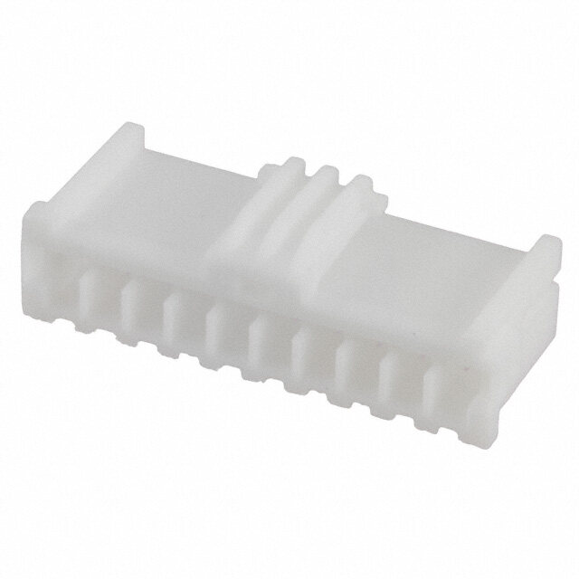
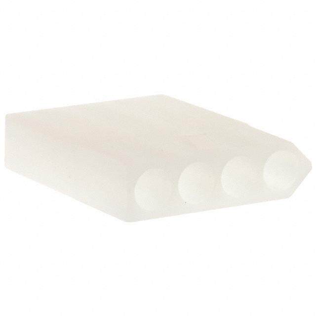
| 描述 | VARISTOR 389V 6.5KA DISC 20MM |
| 产品分类 | |
| 品牌 | Littelfuse Inc |
| 数据手册 | |
| 产品图片 |
|
| 产品型号 | V275SM20 |
| rohs | 无铅 / 符合限制有害物质指令(RoHS)规范要求 |
| 产品系列 | SM20 |
| 产品培训模块 | http://www.digikey.cn/PTM/IndividualPTM.page?site=cn&lang=zhs&ptm=25313http://www.digikey.cn/PTM/IndividualPTM.page?site=cn&lang=zhs&ptm=25936 |
| 产品目录绘图 |
|
| 产品目录页面 | |
| 其它名称 | F3547 |
| 包装 | 托盘 - 晶粒 |
| 变阻器电压 | 389V |
| 封装/外壳 | Disc 20mm,接片式 SMD |
| 最大AC电压 | 275VAC |
| 最大DC电压 | 369VDC |
| 标准包装 | 108 |
| 特色产品 | http://www.digikey.com/cn/zh/ph/Littelfuse/sm20series.html |
| 电流-浪涌 | 6.5kA |
| 电路数 | 1 |
| 能量 | 140J |


PDF Datasheet 数据手册内容提取
Varistor Products Surface Mount Varistors > SM20 Series SM20 Varistor Series Description The Littelfuse 20mm SMD Series is a surface-mount metal oxide varistor device, for use in applications requiring hi-energy / transient current capability. The AC rated parts are designed to operate continuously across AC power lines. The DC rated parts are suitable for Automotive applications. The series comprises a Nylon molded package with folded tin plated metal leads for soldering to board. The SMD Series is based on radial 20mm internal varistor element with similar characteristics to the Littelfuse LA / ZA series of varistors. Agency Approvals Features Agency Agency File Number • DC Voltage • Low voltage E320116 Rating 26VDC devices specified for automotive load • AC Voltage Rating dump energy 175 - 320AC • Available in "waffle" • No De-Rating up s to 85°C ambient tray packaging e i r e • Lead-Free, Halogen- S Free and RoHS 0 2 Compliant M S Absolute Maximum Ratings • For ratings of individual members of a series, see Device Ratings and Specifications chart Continuous SM20 Series Units Steady State Applied Voltage: AC Voltage Range (V ) 20 to 320 V M(AC)RMS DC Voltage Range (V ) 26 V M(DC) Transients: Peak Pulse Current (I ) 8/20μs Current Wave, Single Pulse up to 6500 A TM Single Pulse Energy Capability (W ) 10/1000μs Current Wave 165 J TM Load Dump Energy Capability (td>=30ms) 160 J Operating Ambient Temperature Range (T) -40 to +85 OC A Storage Temperature Range (T ) -55 to +125 OC STG Temperature Coefficient (aV) of Clamping Voltage (V) at Specified Test Current <0.01 %/OC C Hi-Pot Encapsulation (COATING Isolation Voltage Capability) 2500 V (Dielectric must withstand indicated DC voltage for one minute per MIL-STD 202, Method 301) COATING Insulation Resistance 1000 MΩ CAUTION: Stresses above those listed in “Absolute Maximum Ratings” may cause permanent damage to the device. This is a stress only rating and operation of the device at these or any other conditions above those indicated in the operational sections of this specification is not implied. ©2010 Littelfuse, Inc. SM20 Series Varistor Specifications are subject to change without notice. Revision: May 11, 2010 Please refer to www.littelfuse.com/series/sm20.html for current information.
Varistor Products Surface Mount Varistors > SM20 Series SM20 Series Ratings & Specifications Maximum Rating (85°C) Specifications (25°C) Continuous Transient Varistor Voltage Maximum Typical Clamping Energy Peak Current at 1mA DC Capacitance V V Voltage RMS DC 10 x 1000μs 8 x 20μs Test Current 8 x 20 μs f = 1MHz W I Part V V TM TM V Min V Max V I C Branding M(AC) M(DC) 1x pulse 1x pulse NOM NOM C PK Number (V) (V) (J) (A) (V) (V) (V) (A) (pF) 20 32 40 V26SM20 26SM20 20 26 2000 63 20 12000 160 (note 1) (10mA) (10mA) V175SM20 175SM20 175 225 90 6500 247 303 455 100 1400 V230SM20 230SM20 230 300 122 6500 324 396 595 100 1100 V250SM20 250SM20 250 330 130 6500 354 429 650 100 1000 V275SM20 275SM20 275 369 140 6500 389 473 710 100 900 V300SM20 300SM20 300 405 165 6500 420 517 775 100 800 V320SM20 320SM20 320 420 150 6500 462 540 810 100 750 1. Energy rating for impulse duration of 30ms minimum to one half of peak current (automotive load dump). Peak Current, Energy and Power Derating Curve Repetitive Surge Capability For applications exceeding 85ºC ambient temperature, the peak V175SM20 - V320SM20 surge current and energy ratings must be reduced as shown below 10,000 5,000 1 2 MODEL SIZE 20mm 10 V175SM20 - V320SM20 2,000 101203 100 1,000 101405 D VALUE 987000 RENT (A) 250000 106 E R 100 OF RAT 6500 GE CU 50 ENT 40 SUR 2100 INDEFINITE C 30 ER 5 P 20 2 10 1 0 20 100 1,000 10,000 -55 50 60 70 80 90 100 110 120 130 140 150 IMPULSE DURATION (μs) AMBIENT TEMPERATURE (oC) Peak Pulse Current Test Waveform for Clamping Voltage st E Te LU100 A V K A E P OF 50 T N E C R E P 0 t O TIME 1 t 1 t 0 = Virtual Origin of Wave 1 T = Time from 10% to 90% of Peak T = Rise Time = 1.25 x T 1 T = Decay Time 2 Example - For an 8/20 μs Current Waveform: 8μs = T = Rise Time 1 20μs = T = Decay Time 2 SM20 Series Varistor ©2010 Littelfuse, Inc. Revision: May 11, 2010 Specifications are subject to change without notice. Please refer to www.littelfuse.com/series/sm20.html for current information.
Varistor Products Surface Mount Varistors > SM20 Series Lead (Pb) Soldering Recommendations The principal techniques used for the soldering of Reflow Solder Profile components in surface mount technology are IR Re-flow and Wave soldering. Typical profiles are shown on the right. 250 The terminals of SM20 series devices are tin plated copper, MAXIMUM TEMPERATURE and the recommended solder is 62/36/2 (Sn/Pb/Ag), 60/40 230°C 200 (Sn/Pb) or 63/37 (Sn/Pb). Littelfuse also recommends an 40-80 C SECONDS RMA solder flux. E ° ABOVE 183°C R 150 U T RAMP RATE Wave soldering is the most strenuous of the processes. RA <2°C/s To avoid the possibility of generating stresses due to PE 100 thermal shock, a preheat stage in the soldering process TEM PREHEAT DWELL is recommended, and the peak temperature of the solder 50 PREHEAT ZONE process should be rigidly controlled. 0 When using a reflow process, care should be taken to 0 0.5 1.0 1.5 2.0 2.5 3.0 3.5 4.0 ensure that the SM20 chip is not subjected to a thermal TIME(MINUTES) gradient steeper than 4 degrees per second; the ideal gradient being 2 degrees per second. During the soldering Wave Solder Profile process, preheating to within 100 degrees of the solder's peak temperature is essential to minimize thermal shock. 300 Once the soldering process has been completed, it is MAXIMUM WAVE 260°C still necessary to ensure that any further thermal shocks 250 are avoided. One possible cause of thermal shock is hot C printed circuit boards being removed from the solder RE ° 200 s process and subjected to cleaning solvents at room TU e RA 150 ri temperature. The boards must be allowed to cool gradually E SECOND PREHEAT e to less than 50ºC before cleaning. TEMP 100 0 S 2 FIRST PREHEAT M 50 S 0 0.0 0.5 1.0 1.5 2.0 2.5 3.0 3.5 4.0 4.5 TIME (MINUTES) Lead–free (Pb-free) Soldering Recommendations The terminals of SM20 series devices are tin plated copper, Lead–free Re-flow Solder Profile and the recommended Lead-free solder is 96.5/3.0/0.5 (SnAgCu) with an RMA flux, though there is a wide selection of pastes and fluxes available that should be 300 MAXIMUM TEMPERATURE 250˚C, compatible. TIME WITHIN 5˚C OF PEAK 250 20 SECONDS MAXIMUM The reflow profile must be constrained by the maximums RAMP RATE C in the Lead–free Reflow Profile. For Lead–free Wave E °200 <3˚C/s 60 - 150 SEC R > 217˚C soldering, the Wave Solder Profile still applies. TU A150 R E Note: the Lead–free paste, flux and profile were used for MP E100 evaluation purposes by Littelfuse, based upon industry T PREHEAT ZONE standards and practices. There are multiple choices of all 50 three available, it is advised that the customer explores the optimum combination for their process as processes vary 0 0 1.0 2.0 3.0 4.0 5.0 6.0 7.0 considerably from site to site. TIME (MINUTES) ©2010 Littelfuse, Inc. SM20 Series Varistor Specifications are subject to change without notice. Revision: May 11, 2010 Please refer to www.littelfuse.com/series/sm20.html for current information.
Varistor Products Surface Mount Varistors > SM20 Series Product Dimensions Part Numbering System (cid:25) Millimeters V 275 SM20 Symbol Min Max For “VARISTOR” (cid:24) D --- 26 (diameter) Max Voltage Rating (Two or three digits -- refer to H1 --- 10.5 ratings and specifications table) H2 1.0 -- SM20 SERIES t 0.50 0.70 (cid:23)(cid:6) S1 32.5 35 (cid:23)(cid:7) (cid:22) S2 3.0 4.5 (cid:5)(cid:6) (cid:5)(cid:7) W 6.2 6.6 (cid:3) (cid:2) (cid:4)(cid:2) (cid:5)(cid:8)(cid:9)(cid:10)(cid:11)(cid:12)(cid:13)(cid:14)(cid:15)(cid:16)(cid:17)(cid:18)(cid:10)(cid:16)(cid:19)(cid:18)(cid:20)(cid:8)(cid:21)(cid:22) Packaging Standard Packaging is in "Waffle" trays: Quantity per tray: 36 pieces Quantity per box: 108 pieces 192 mm 30 mm typical 11.7 mm 8.4 mm pocket typical depth 30 mm typical 192 mm Radius 30 mm typical SM20 Series Varistor ©2010 Littelfuse, Inc. Revision: May 11, 2010 Specifications are subject to change without notice. Please refer to www.littelfuse.com/series/sm20.html for current information.