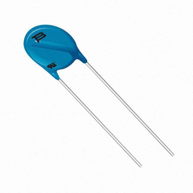
ICGOO在线商城 > 电路保护 > TVS - 变阻器,MOV > V275LA4P
- 型号: V275LA4P
- 制造商: Littelfuse
- 库位|库存: xxxx|xxxx
- 要求:
| 数量阶梯 | 香港交货 | 国内含税 |
| +xxxx | $xxxx | ¥xxxx |
查看当月历史价格
查看今年历史价格
V275LA4P产品简介:
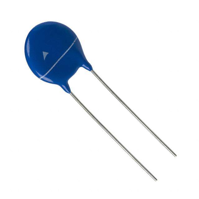
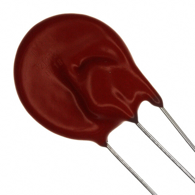
ICGOO电子元器件商城为您提供V275LA4P由Littelfuse设计生产,在icgoo商城现货销售,并且可以通过原厂、代理商等渠道进行代购。 V275LA4P价格参考。LittelfuseV275LA4P封装/规格:TVS - 变阻器,MOV, 430V 1.2kA Varistor 1 Circuit 通孔 圆片式 7mm。您可以下载V275LA4P参考资料、Datasheet数据手册功能说明书,资料中有V275LA4P 详细功能的应用电路图电压和使用方法及教程。
| 参数 | 数值 |
| 产品目录 | |
| 描述 | VARISTOR 389V 1.2KA DISC 7MM压敏电阻 275V 80pF |
| 产品分类 | |
| 品牌 | Littelfuse Inc |
| 产品手册 | |
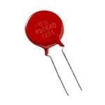
| 产品图片 |
|
| rohs | 符合RoHS无铅 / 符合限制有害物质指令(RoHS)规范要求 |
| 产品系列 | Littelfuse V275LA4PLA |
| 数据手册 | |
| 产品型号 | V275LA4P |
| 产品 | MOV |
| 产品培训模块 | http://www.digikey.cn/PTM/IndividualPTM.page?site=cn&lang=zhs&ptm=25313 |
| 产品目录绘图 |
|
| 产品目录页面 | |
| 产品种类 | 压敏电阻 |
| 其它名称 | F3009 |
| 包装 | 散装 |
| 变阻器电压 | 389 V to 473 V |
| 商标 | Littelfuse |
| 外壳直径 | 7 mm |
| 安装 | Radial |
| 封装 | Bulk |
| 封装/外壳 | 圆盘 7mm |
| 尺寸 | 7 mm Dia. x 5.6 mm H |
| 峰值浪涌电流 | 1.2 kA |
| 工作温度范围 | - 55 C to + 85 C |
| 工厂包装数量 | 1500 |
| 引线间隔 | 4 mm to 6 mm |
| 最大AC电压 | 275VAC |
| 最大DC电压 | 369VDC |
| 标准包装 | 1,500 |
| 浪涌能量额定值 | 23 J |
| 电压额定值AC | 275 V |
| 电压额定值DC | 369 V |
| 电容 | 80 pF |
| 电流-浪涌 | 1.2kA |
| 电流额定值 | 1.2 kA |
| 电路数 | 1 |
| 直径 | 7 mm |
| 端接类型 | Radial |
| 系列 | LA |
| 能量 | 23J |
| 钳位电压 | 710 V |


- 商务部:美国ITC正式对集成电路等产品启动337调查
- 曝三星4nm工艺存在良率问题 高通将骁龙8 Gen1或转产台积电
- 太阳诱电将投资9.5亿元在常州建新厂生产MLCC 预计2023年完工
- 英特尔发布欧洲新工厂建设计划 深化IDM 2.0 战略
- 台积电先进制程称霸业界 有大客户加持明年业绩稳了
- 达到5530亿美元!SIA预计今年全球半导体销售额将创下新高
- 英特尔拟将自动驾驶子公司Mobileye上市 估值或超500亿美元
- 三星加码芯片和SET,合并消费电子和移动部门,撤换高东真等 CEO
- 三星电子宣布重大人事变动 还合并消费电子和移动部门
- 海关总署:前11个月进口集成电路产品价值2.52万亿元 增长14.8%
PDF Datasheet 数据手册内容提取
Metal-Oxide Varistors (MOVs) Radial Lead Varistors > LA Varistor Series LA Varistor Series RoHS Description The LA Varistor Series of transient voltage surge suppressors are radial leaded varistors (MOVs) that are designed to be operated continuously across AC power lines. These UL recognized varistors require very little mounting space, and are offered in various standard lead form options. The LA Varistor Series are available in four model sizes: 7mm, 10mm, 14mm and 20mm; and have a V voltage range from 130V to 1000V, and an M(AC)RMS energy absorption capability up to 360J. Some LA Series model numbers are available with clamping voltage selections, designated by a model number suffix of Agency Approvals either A or B. The 'A' selection is the standard model; Agency File the 'B' selection provides a lower clamping voltage. Agency Agency Approval Number See LA Series Device Ratings and Specifications UL1449 E320116 Table for part number and brand information. CECC 42201-006 IEC 61051-1 Features 116895 IEC 61051-2 IEC 60950-1 (Annex Q) for 14mm and 20mm only • Lead–free, Halogen- • No derating up to CECC 42201-006 Free and RoHS 85ºC ambient IEC 61051-1 E1273/F compliant. IEC 61051-2 • Available in tape and IEC 60950-1 (Annex Q) for 14mm and 20mm only • Energy absorption reel or bulk pack capability (W ) TM up to 360J Additional Information • Wide operating voltage range V 130V to 1000V M(AC)RMS Datasheet Resources Samples Absolute Maximum Ratings • For ratings of individual members of a series, see Device Ratings and Specifications chart Continuous LA Series Units Steady State Applied Voltage: AC Voltage Range (V ) 130 to 1000 V M(AC)RMS DC Voltage Range (V ) 175 to 1200 V M(DC) Transients: Peak Pulse Current (I ) TM For 8/20µs Current Wave (See Figure 2) 1200 to 6500 A Single Pulse Energy Range For 10/1000µs Current Wave (W ) 11 to 360 J TM Operating Ambient Temperature Range (T) -55 to +85 OC A Storage Temperature Range (T ) -55 to +125 OC STG Temperature Coefficient (aV) of Clamping Voltage (V) at Specified Test Current <0.01 %/OC C Hi-Pot Encapsulation (COATING Isolation Voltage Capability) 2500 V (Dielectric must withstand indicated DC voltage for one minute per MIL-STD 202, Method 301) COATING Insulation Resistance 1000 MΩ CAUTION: Stresses above those listed in “Absolute Maximum Ratings” may cause permanent damage to the device. This is a stress only rating and operation of the device at these or any other conditions above those indicated in the operational sections of this specification is not implied. © 2019 Littelfuse, Inc. Specifications are subject to change without notice. Revised: 12/17/19
Metal-Oxide Varistors (MOVs) Radial Lead Varistors > LA Varistor Series LA Series Ratings & Specifications Maximum Rating (85°C) Specifications (25°C) Continuous Transient Typical Varistor Voltage at Maximum Clamping NuPmarbt er Branding MDoi(dsmce mlD S)iaiz. e VRMS VDC Exn 1e0r0g0yµ 1s0 CurP2re0enµatks 8 x DC Te1stm CAurrent 8V xo l2ta0g µes tCa1naMpceaH cfzi -= V V W I V Min V Max V I C M(AC) M(DC) TM TM NOM NOM C PK (V) (V) (J) (A) (V) (V) (V) (A) (pF) V130LA1P P1301 7 130 175 11 1200 198 242 390 10 180 V130LA2P P1302 7 130 175 11 1200 184.5 225.5 340 10 180 V130LA5P P1305 10 130 175 20 2500 184.5 225.5 340 25 450 V130LA10AP P130L10 14 130 175 38 4500 184.5 225.5 340 50 1000 V130LA20AP P130L20 20 130 175 70 6500 184.5 225.5 340 100 1900 V130LA20BP P130L20B 20 130 175 70 6500 190 220 325 100 1900 V140LA2P P1402 7 140 180 12 1200 198 242 360 10 160 V140LA5P P1405 10 140 180 22 2500 198 242 360 25 400 V140LA10AP P140L10 14 140 180 42 4500 198 242 360 50 900 V140LA20AP P140L20 20 140 180 75 6500 198 242 340 100 1750 V150LA1P P1501 7 150 200 13 1200 225 275 430 10 150 V150LA2P P1502 7 150 200 13 1200 216 264 395 10 150 V150LA5P P1505 10 150 200 25 2500 216 264 395 25 360 V150LA10AP P150L10 14 150 200 45 4500 216 264 395 50 800 V150LA20AP P150L20 20 150 200 80 6500 216 264 395 100 1600 V150LA20BP P150L20B 20 150 200 80 6500 216 243 360 100 1600 V175LA2P P1752 7 175 225 15 1200 243 297 455 10 130 V175LA5P P1755 10 175 225 30 2500 243 297 455 25 350 V175LA10AP P175L10 14 175 225 55 4500 243 297 455 50 700 V175LA20AP P175L20 20 175 225 90 6500 243 297 455 100 1400 V230LA4P P2304 7 230 300 20 1200 324 396 595 10 100 V230LA10P P230L 10 230 300 35 2500 324 396 595 25 250 V230LA20AP P230L20 14 230 300 70 4500 324 396 595 50 550 V230LA40AP P230L40 20 230 300 122 6500 324 396 595 100 1100 V250LA2P P2502 7 250 330 21 1200 369 451 730 10 90 V250LA4P P2504 7 250 330 21 1200 351 429 650 10 90 V250LA10P P250L 10 250 330 40 2500 351 429 650 25 220 V250LA20AP P250L20 14 250 330 72 4500 351 429 650 50 500 V250LA40AP P250L40 20 250 330 130 6500 351 429 650 100 1000 V250LA40BP P250L40B 20 250 330 130 6500 354 413 620 100 1000 V275LA2P P2752 7 275 369 23 1200 405 495 775 10 80 V275LA4P P2754 7 275 369 23 1200 387 473 710 10 80 V275LA10P P275L 10 275 369 45 2500 387 473 710 25 200 V275LA20AP P275L20 14 275 369 75 4500 387 473 710 50 450 V275LA40AP P275L40 20 275 369 140 6500 387 473 710 100 900 V275LA40BP P275L40B 20 275 369 140 6500 389 453 680 100 900 V300LA2P P3002 7 300 405 25 1200 441 539 870 10 70 V300LA4P P3004 7 300 405 25 1200 423 517 775 10 70 V300LA10P P300L 10 300 405 46 2500 423 517 775 25 180 V300LA20AP P300L20 14 300 405 77 4500 423 517 775 50 400 V300LA40AP P300L40 20 300 405 165 6500 423 517 775 100 800 V320LA7P P3207 7 320 420 25 1200 459 561 850 10 65 V320LA10P P320L 10 320 420 48 2500 459 561 850 25 170 V320LA20AP P320L20 14 320 420 80 4500 459 561 850 50 380 V320LA40BP P320L40 20 320 420 150 6500 462 540 810 100 750 V385LA7P P3857 7 385 505 27 1200 558 682 1025 10 60 V385LA10P P385L 10 385 505 51 2500 558 682 1025 25 160 V385LA20AP P385L20 14 385 505 85 4500 558 682 1025 50 360 V385LA40BP P385L40 20 385 505 160 6500 558 682 1025 100 700 © 2019 Littelfuse, Inc. Specifications are subject to change without notice. Revised: 12/17/19
Metal-Oxide Varistors (MOVs) Radial Lead Varistors > LA Varistor Series LA Series Ratings & Specifications (Continued...) Maximum Rating (85°C) Specifications (25°C) Continuous Transient Typical Varistor Voltage at Maximum Clamping NuPmarbt er Branding MDoi(dsmce mlD S)iaiz. e VRMS VDC Exn 1e0r0g0yµ 1s0 CurP2re0enµatks 8 x DC Te1stm CAurrent 8V xo l2ta0g µes tCa1naMpceaH cfzi -= V V W I V Min V Max V I C M(AC) M(DC) TM TM NOM NOM C PK (V) (V) (J) (A) (V) (V) (V) (A) (pF) V420LA7P P4207 7 420 560 30 1200 612 748 1120 10 55 V420LA10P P420L 10 420 560 55 2500 612 748 1120 25 140 V420LA20AP P420L20 14 420 560 90 4500 612 748 1120 50 300 V420LA40BP P420L40 20 420 560 160 6500 610 720 1060 100 600 V460LA7P P4607 7 460 615 37 1200 643.5 786.5 1190 10 55 V460LA10P P460L 10 460 615 56 2500 643.5 786.5 1190 25 120 V460LA20AP P460L20 14 460 615 100 4500 643.5 786.5 1190 50 280 V460LA40BP P460L40 20 460 615 170 6500 643.5 755.5 1110 100 560 V480LA7P P4807 7 480 640 35 1200 675 825 1240 10 50 V480LA10P P480L 10 480 640 60 2500 675 825 1240 25 120 V480LA40AP P480L40 14 480 640 105 4500 675 825 1240 50 270 V480LA80BP P480L80 20 480 640 180 6500 675 790 1160 100 550 V510LA10P P510L 10 510 675 63 2500 738 902 1350 25 100 V510LA40AP P510L40 14 510 675 110 4500 738 902 1350 50 250 V510LA80BP P510L80 20 510 675 190 6500 738 860 1280 100 500 V575LA10P P575L 10 575 730 65 2500 819 1001 1500 25 90 V575LA40AP P575L40 14 575 730 120 4500 819 1001 1500 50 220 V575LA80BP P575L80 20 575 730 220 6500 819 960 1410 100 450 V625LA10P P625L 10 625 825 67 2500 900 1100 1650 25 80 V625LA40AP P625L40 14 625 825 125 4500 900 1100 1650 50 210 V625LA80BP P625L80 20 625 825 230 6500 900 1100 1650 100 425 V680LA10P P680L 10 680 875 75 2500 990 1210 1875 25 65 V680LA80AP P680L80 14 680 875 145 4500 990 1210 1875 50 190 V680LA100BP P680L100 20 680 875 260 6500 990 1130 1700 100 380 V660LA10P P660L 10 660 850 70 2500 972 1188 1820 25 70 V660LA50AP P660L50 14 660 850 140 4500 972 1188 1820 50 200 V660LA100BP P660L100 20 660 850 250 6500 940 1100 1650 100 400 V1000LA80AP P1000L8 14 1000 1200 220 4500 1500 1800 2700 50 130 V1000LA160BP P1000L16 20 1000 1200 360 6500 1425 1600 2420 100 250 Note: Average power dissipation of transients not to exceed 0.25W, 0.4W, 0.6W or 1W for model sizes 7mm, 10mm, 14mm and 20mm, respectively. Phenolic Coating Option -- LA Series Varistors for Hi-Temperature Operating Conditions: • Phenolic–coated LA Series devices are available with improved maximum operating maximum temperature 125°C. • These devices also have improved temperature cycling performance capability. • Ratings and Specifications are as per standard LA Series except Hi–Pot Encapsulation (Isolation Voltage Capability) = 500V. • These devices are not UL, CSA, VDE or CECC certified. • To order: add X1347 to end of part number (e.g. V230LA20APX1347). • Product marking: LF 9 P230P20 Lead-Free, YYWW Phenolic Coated Halogen-Free Option & RoHS Compliant Identifier Indicator © 2019 Littelfuse, Inc. Specifications are subject to change without notice. Revised: 12/17/19
Metal-Oxide Varistors (MOVs) Radial Lead Varistors > LA Varistor Series Copper Electrode Option: • Add 'W' to the end of the part number (e.g. V230LA20APW) • Product marking: LF 9 P230L20W Lead-Free, YYWW Copper Electrode Halogen-Free Option & RoHS Compliant Identifier Indicator Current Energy and Power Dissipation Ratings Should transients occur in rapid succession, the average device. The operating values of a MOV need to be derated power dissipation is the energy (watt-seconds) per pulse at high temperatures as shown above. Because varistors times the number of pulses per second. The power so only dissipate a relatively small amount of average power developed must be within the specifications shown on the they are not suitable for repetitive applications that involve Device Ratings and Specifications Table for the specific substantial amounts of average power dissipation. Figure 1A - Power Derating for Epoxy Coated Figure 1B - Power Derating for Phenolic Coated 100 100 E 90 90 ED VALU 8700 ed Value 8700 OF RAT 6500 e of Rat 6500 PERCENT 432000 Percentag 432000 10 10 0 0 -55 50 60 70 80 90 100 110 120 130 140 150 -55 50 60 70 80 90 100 110 120 130 140 150 AMBIENT TEMPERATURE (oC) Ambient Temperature (ºC) FIGURE 1. CURRENT, ENERGY AND POWER DERATING Peak Pulse CuCrrUeRnVtE Test Waveform E 100 U AL 0 = Virtual Origin of Wave V 90 1 T = Time from 10% to 90% of Peak AK T1 = Rise Time = 1.25 x T OF PE 50 TE2x =am Dpelcea y- FToimr aen 8/20 µs Current Waveform: T CEN 8µs = T1 = Rise Time PER 20µs = T2 = Decay Time 10 O1 T TIME Figure 2 T1 T2 O1 = Virtual Origin of Wave T = Time From 10% to 90% of Peak T1 = Virtual Front time = 1.25 • t T2 = Virtual Time to Half Value (Impulse Duration) Example: For an 8/20µs Current Waveform: 8 s = T1 = Virtual Front Time 20 s = T2 = Virtual Time to Half Value FIGURE 2. PEAK PULSE CURRENT TEST WAVEFORM © 2019 Littelfuse, Inc. Specifications are subject to change without notice. Revised: 12/17/19
Metal-Oxide Varistors (MOVs) Radial Lead Varistors > LA Varistor Series Transient V-I Characteristics Curves Pulse Rating Curves Maximum Clamping Voltage for 7mm Parts Repetitive Surge Capability for 7mm Parts Transient V-I Characteristics Curves V130LA1(P) - V300LA2(P) V130LA1(P) - V480LA7(P) 6,000 4,000 5,000 MAXIMUM CLAMPING VOLTAGE 2,000 MAXIMUM CLAMPING VOLTAGE 5,000 MODEL SIZE 7mm 3,000 1 MODEL SIZE 7mm MODEL SIZE 7mm 1 MODEL SIZE 10mm 4,000 130 TO 300VM(AC) RATING 1,000 130 TO 300VM(AC) RATING V130LA1(P) - V480LA7(P) 2,000 V130LA5(P) - V680LA10(P) XIMUM PEAK VOLTS (V) 312,,,987650000000000000000000 TVA3 =0 0-5L5Ao2C(P T)O 85oC V2V7255L0AL2A(P2)(P) SURGE CURRENT (A)XIMUM PEAK VOLTS (V)21215,,005210009876543000000000000000000000000121052TA = -55oC TO 85oC V30V0120L7V1A35204L15V40(A0P2154L03)(A06P4L)(AP4)(P) SURGE CURRENT (A)1,2150005200000000 125 101201301401506 MA 400 V150LA1(P) MA 2500 INDEFINITE V15V01L7A52L(AP2)(P) 10 INDEFINITE 300 2 V140LA2(P) 5 V130LA1(P) V130LA2(P) 200 1010 2 10-3 10-2 10-1 100 101 102 103 104 2100-3 10-2 10010-1 100 110,0100 102 10310,001004 20 100 1,000 10,000 FTigruaren 3sient V-I CharacPEteAKr iAsMtPiEcRsE SC (Au)rves Figure 4 IMPUPLESAEK DAUMRPAETRIOENS ((μAs)) IMPULSE DURATION (μs) Transient V-I Characteristics Curves V130L65F,,A00IG20000(UP)R -E MV A33X0.0IMCLUALMA4( MCP)LPAINMGPI NVGO VLOTALTGAEGE FOR V130LA1(P) - V300LA2(P) Nwoa4vt,ee0f: o0RFrF0emIpIG)e GatinUtUdiMv RUeRA LsE1uEX4 rg4I1 Me494 c4.U.a0pM.C7aSV.b 3LCiU1 l(iAEtL3ydRA M0iitsGiMLo qPnEAuP 4aI IN1)lCN itfi(eGeGUPsdt )RaVcV no-OROdn V dLtEieLTt4siNToAt8neAGT.d0 GEb LaRAEseA 7dFT o(OPnIN 8)R/ G2 0Vu Cs1 cU3ur0RreLVntA Ew2Sav( PeFfo)O r-m RV (n 3ot0 co0mLbAina4ti(oPn ) FIGURE 15. SVU13R0GLEA 5C(UP)R -R VE6N8T0 LRAA1T0I(NP)G CURVES FOR MAXIMUM PEAK VOLTS (V) 654312,,,,,,987654300000000000000000000000000000000 MM1TVVV3AAO0113 =XD 530T I000-EOM5LLLL 5UAAA3 oS11M20CI(((0Z PPP CVTE)))OML 7A( 8AmM5CmPo) CIRNAGT VINOGLTVA2GV7E255L0AL2A(P2)(P) MAXIMUM PEAK VOLTS (V)MAXIMUM PEAK VOLTS (V)MAXIMUM PEAK VOLTS (V)432143125321,,,,000098765432,,,,,,,,29876543000000000000000000000000000000000000000000000000000000000000100000-3MMT3MM1T2AM1TAO3A0 VVV3AAO=0XO DT0113= XD =ITD -53EO0 MTI5-E OM0010-EL5O 5U5L0LL4L 5 ULo3 5S AA-8AMo3S 2MC0oSI011C20IZ 0C ZVI ((C(0T ZCVEPPTP EVMTOLEOML ))) OM7A(7 A( A781m8A( MmM8A0Cm55Cm5mCP-o)Pom)1 o)C ICRIRN CNRAAGGATTVV T VVIIN44NI1OON068GGLGL000TTVLLAAV3AAGG0V277VV0E72E((1L1PP257V03AV5L5))2010A4L15VLL(4A2V0P2AA0(4L13P)2L2(5AV0P)(A(0P4L1P)12L(7A))0P(A5P42)2L()P(AP)2)V(P41)2003LA7(P1)04 MAXIMUM PEAK VOLTS (V)321,,,SURGE CURRENT (A)000987654321MAXIMUM PEAK VOLTS (V)00000000000010000000000005210265431,,,002150-,,,,,,30000009876540052100000000000000000000500M1T0000000000000003AO0 =D1 T12 I5V-ENO0V5M1MT4L1-D 513A232 AOo7SE0 00=CX5D IF0LTZ LI IV-ETAOMNEA5OML1 5IU5174T 0( oS(08AmM2E(PC5P-CI01mZ )o )C)VTE CROML 1AA( 08ATMm5C1INPo0)m GCI0RNVAG3T 0VVINV0O2L1G71VL3AV05T2MV04L11A5V11LV(4AOV00GP23A0124L12D30)E20LV7(5AV01LPE(A3502P40L1VAL)2LL151(7A)421 P(0AA00S5P4031)522LL1I(0A)0ZP(0AA6LP(E()21PAP) 0()11P) (4-0P) 1mV()0P3m3)20LA2100A4(P) SURGE CURRENT (A)521,,,0021500052100000000500000 12I5N1DEFINITE MV3O180D512LE0A1L30 21S400IA1Z50E(P6 1) 4- mV1m000LA80A(P) 20010-3 10-2 10-1PEAK1 0A0MPER1E0S1 (A) 102 103 104 FiguFrI1eG50 010U500R-3E 3.1C0L-2AMPI1N0G-1 VPPOEELAATK1KA0 AA0GMMEPP EFERRO1EER0SS1 V ((AA1)3)0L1A021V(3VP23)08 -L51 AVL07A33(07P(0P)L)A1204(P) FIGURE2300 24200.0CLAMPING1 V0PO0IEMLATPKAU GALMESP EFE DORURERS VA (1TA3I)O0N1L,A 0(μ20s(0P)) - V3V001V3L1V0A41L405AL(05PAL1()5PA0 (,)5P0(0)P0) 220 100IMPULSE DURATION1, 0(μ0s0) 10,000 FIGURE 3. CLAMPING VOLTAGE FOR V130LA1(P) - V300LA2(P) V320FLIGAU7(RPE) -4 V.4C8100LL-A3AM7P(PI1N)0G-2 VOL1T0A-1GE F1O00R V131001LA2(P1)0 -2 V30010L3A4(P)1 04 FIGUR1E0- 316. S1U0R-2GE C1U0-R1RENT10 R0ATIN1G01 CURV1E0S2 FOR1 03 104 FIGURE 17. SURGE CURRENT RATING CURVES FOR PEAK AMPERES (A) PEAK AMPERES (A) 6,000 V130LA10A(P) - V320LA20A(P) V385LA20A(P) - V1000LA80A(P) MAXIMUM PEAK VOLTS (V)5321,,,,000050000000000 3MMT2AAO0 =X DT I1-EOM50L 5U4- 3oS8MCI0Z VCTEMOL1 7A(0 A8mM-C52mPo) CIRNAG1T0VV VIN-441O68GL00TLLAAA1G770E((0PP)) 101 V3V120V30284L52AL07AL(A17P0(7P)3(P)) 104 FMAXIMUM PEAK VOLTS (V)iMAXIMUM PEAK VOLTS (V)MAXIMUM PEAK VOLTS (V)gu53216543125321,,,,Fr00005,,,,,,e,,,,02000009876543I000000000G 0000000000000000000000060000000000000010000U30MMTR2A-3AOMMT30V VVEV0A=XMM1T D4AOT3301 3A I21-EOAO5=XM027 D05T 00 =LX.500I D 5-UEOLT4M- L5LL1I3oS-EAO8CMLM A505AAUC6I0L 1 5oZ-UL5 S1184M V 02CToCS(E00AMI20(PMOLZC P((I1 0 VCMTZ7 PP)AE(0 C)VTAM8OmELM))- POMLC512A ( 1m1PAAo08)I( M00 8ANCCIm5MR-Nm5CP1o)GAPPmoG )1CmIRT CENI R0VV NVVIAAGN-44AG1OOTK68TG V IL00V LIN1ATNOLLT0OVVGAMAAG0AL66L1GT77PT26G0EA((AE500PPVEGGRLL2))AA EEEV7F111S502VO00L15 12(((0AR0APP31L1V)0)) V0A6L(138AP0V0121)(0L3V01P022A(0V3)LP021V84A)L0521VA7(L03P1V7(AL0VVVP4)(1AL117P0554500A)(7L 718P0)33(5-A050LP )(VL5PALL)A(AA4)5P(1118)P1100000)0(((LPPP44A)))/7(P) MAXIMUM PEAK VOLTS (V) 54312SURGE CURRENT (A),,,,,MAXIMUM PEAK VOLTS (V)0200009876543F100000000000000215I00000000000001G,654312,,,00215000,,,,,,9876540U005210000000000-30000000V000521000000000000VR000000M1MT2000000413AE02AO70 0 =X5D I16LTN VL1I-EMM1TAO.MA50D13AL1 5AO-U57CE40 02 oS(=5XM2D F(PLTCPL I0IIZ-E )OAMN AC)5VVVTELM 5I1UOML333T 10o1SA20M(2 EP00A8AC00IM0-Zm 51CI( 1LLCVNTPP02oE)AAmOPM LC0I)G R1N221AE( 5A0084AG MAVTAA5mC KVOPI1o(()Nm PP0O CIARLNG0))LMTAGTATPA VVGIEGN2OREEVG71LE50 2VTFMVSL51A12A1O 00OG(331LA120RDE000A)L1L(3 E1A1V0PA0L11,41)10(02 00PS13005V2(0)VIP00AZ2VV62)L(E721P5VA5 3320)1VL00 50L4-1AL1L (mAV050AP2AL2303m502)A20L( A05PA0-A(A (L)5V(PPP(A()P4)P1)4)20)0401BL0(P,A0)10 00(P) SURGE CURRENT (A)10521,,,,00215000005210000000052100000020I1NDEFINITE102015 MV3O8D510LE1A2L01 43S1001I,4BZ001(E05P0 02)6 0- mV1m000LA160B1(0P,0) 00 PEAK AMPERES (A) FIGURE 5. CLAMPING VPOELATKA AGMEP FEORERS V (3A2)0LA7(P) -V V46408L0AL1A07(P(P)) FIGURE3 060. CLAMPING VOLTIMAGPUEL FSOE RD UVR1A3T0ILOAN5 ((μPs)) - V42V01LV4A1051L00AL(1PA01)A 0(AP()P) IMPULSE DURATION (μs) V385LA10(P) V130LA10A(P) FIGURE 5. CLAMPING VOLTAGE FOR V320LA7(P) - V480LA7(P) FIGU50R0E 6. CLAMPING VOLTAGE FOR V130LA5(P) - V420LA10(P) FIG2U0R0E 18. SURGE CURRENT RATING CURVES FOR FIGURE 19. SURGE CURRENT RATING CURVES FOR 10-3 10-2 10-1 100 101 102 103 104 10-3 V1103-02LA201A0-(1P) - V130200LA4100B1(P) 102 103 104 V385LA40B(P) - V1000LA160B(P) MAXIMUM PEAK VOLTS (V)5321,,,,000000000000 3MMTVV0AAO330 =X02 DT 00I-EOM5LLL 5AAU6 oS118MC00I0Z (( VCTPPEMOL)) 1A( A08MCm5Po)m CIRNAGT VINOVVGL66T26A50GLLAAE1100((PPV))680LA10(PVV)557105LLAA1100((PP)) MAXIMUM PEAK VOLTS (V)MAXIMUM PEAK VOLTS (V)F5321654312,,,,I0000G,,,,,,9876540000000000000000000000U0000000000000000R3MMTVVE0AAO330V MM1T=7X02 D1T3A. 00AOI7-EO0M 5LL=5XD LC T5AAUL 6I -EOMoS11AL85MVVLC00I 051AU33Z3 (( 0VoCST20PPM2MEACMO00IL0)) Z (1 LLPACV(T PEA08AAMOMLI)C m5N221A( Po)0084Am MGCIRAA5mCNPo ((A)VmGPP CITRNOP ))VIANGEOLTVVG ATVIL66NKATO26AG G50LAGTLLMEAAAEG P11F00EEO((RPPVR))E6 SV8VV 02V(32AL7205A)53001L0LL0ALAA(2AP2012VVVV)0A005544A(A(7186(PP0P(500)P)LLLL) )A-AAA V111100006((((8PPPP0))))L/A10(P) MAXIMUM PEAK VOLTS (V)F654312I,,,,,,9876543000000G00000000000000000000U000000REVMM1T 13A8AO70 .=5XD TL CI-EOMA5VVLL 51U333 A0oS20M2ACM00I0Z ( LLCVTPEPAAOML) I221A( N0084AMAA5mCGPo(()m PP CIVRN))OAGTL VITNPOAGELGTAASEKGp eAFEcMOifiPcRaEtV iVVRo2Vn21E7s253 S53a0L0r0 Le(ALLA As2AA)u20V2b01Aj01eAV04(Ac(PA10tP( 5)PtL(o)0PA) cL)1h© A0-a 1nA2V0g0(3R1AeP9e2 (w) vP0LiiisLtt)hteeAodluf:2 ut10 s2neA/o1, t 7Iinc/1ce9.. VV448600LLAA1100((PP))/ 530000 V3V8155L0AL1A01(0PA)(P) 200 V130LA10A(P) V385LA10(P) 10-3 10-2 10-1 100 101 1V012V3014L0A1L10A03A10(PA)(P1)04 10-3 10-2 10-1 100 101 102 103 104 500 200 PEAK AMPERES (A) PEAK AMPERES (A) 10-3 10-2 10-1 100 101 102 103 104 10-3 10-2 10-1 100 101 102 103 104 PEAK AMPERES (A) FIGURE 7. CLAMPING VOPLETAAKG AEM FPOERRE VS3 (0A0)LA10(P) - V680LA10(P) FIGURE 8. CLAMPING VOLTAGE FOR V130LA10A(P) - V320LA20A FIGURE 7. CLAMPING VOLTAGE FOR V300LA10(P) - V680LA10(P) FIGURE 8. CLAMPING VOLTAGE FOR V130LA10A(P) - V320LA20A
Transient V-I Characteristics Curves Transient V-I Characteristics Curves 6,000 4,000 5,000 MAXIMUM CLAMPING VOLTAGE MAXIMUM CLAMPING VOLTAGE 65,,000000 MMAOXDIEMLU SMIZ CEL 7AmMmPING VOLTAGE 4343,,,,000000000000 MMM1T3AAOO0 XD=D TI EM-EO5LLU 5 3 SoMS0ICI0Z ZC VETELOM 7A7( m8AMm5CmPmo)I CNRGAT VINOGLTAGE 32,,000000 M1T3AO0 =D T -EO5L 53 oS0CI0Z VTEOM 7( 8Am5Cmo) CRATINGV300LA4(P) XIMUM PEAK VOLTS (V) 4312,,,,987650000000000000000000000 1TV3A03 = 0T 0-O5L 5A3o20C(0P VT)OM( 8A5Co) CRATINGV2V7255L0AL2A(P2)(P) MAXIMUM PEAK VOLTS (V)XIMUM PEAK VOLTS (V)2112,,,,009876543987654000000000000000000000000000000000000 1T3AVV0 13= 5T0 -0O05LL 53AAo012C0(( PPVT))OM( 8A5Co) CRATINGVV320VV70225L7V5LA520A4L5VL2(A0AP2(4LP32)(A)0(PP4L)()AP4MR)(Pa)deitaal Lle-Oadx Viadreis tVoMAXIMUM PEAK VOLTS (V)ras1,r 098765432 i000000000>000000000s tLoAr Vsa r(iMstOorV Sse)ries V27V52L5VAV024L13(5AV0P04L1)L(7APA54)2L(P(AP)2)(P) MA 400 V150LA1(P) MA 230000 V130LA1(P) V15V01L7A52L(AP2)(P) V13V01L4A02L(AP2)(P) 300 200 V140LA2(P) 100 V130LA1(P) 10-3 10-2 10-1 100 V110310LA2(P1)02 103 104 10-3 10-2 10-1 100 101 102 103 104 20010-3 10-2 10-1 100 101 102 103 104 Tran1s0i10e0n-3t V-I1 0C-2hara1c0t-e1rPiEsAtiK1c0 As0M CPuERrEv10Se1 s(A )(Co10n2tinu1e0d3...) 104 Pulse Rating CurvesP (ECAKo nAMtiPnEuReESd .(.A.)) PEAK AMPERES (A) FIGURE 3. CLAMPING VPOELATKA AGMEP FEORERS V (1A3)0LA1(P) - V300LA2(P) FIGURE 4. CLAMPING VOLTAGE FOR V130LA2(P) - V300LA4(P) Maximum Clamping Voltage for 10mm Parts Repetitive Surge Capability for 10mm Parts FIGURE 3. CLAMPING VOLTAGE FOR V130LA1(P) - V300LA2(P) FIGURE 4. CLAMPING VOLTAGE FOR V130LA2(P) - V300LA4(P) 6,000 MAXIMUM PEAK VOLTS (V)5321,,,,000000000000 3MMT2AAO0 =X DT I-EOM5L 5U4 oS8MCI0Z VCTEMOL 7A( A8mMC5mPo) CIRNAGTVV VIN44O68GL00TLLAAAG77E((PP)) V420LA7(P) V1MAXIMUM PEAK VOLTS (V)3MAXIMUM PEAK VOLTS (V)0SURGE CURRENT (A)5321L21654312,,,,A,,0000,,,,,,0021500000987654000005005210000000000000000000(000050000P0000000000003MMT) 2A1-121AO0 0IV V5NV=X DMM1T2T44 13AID-EO2MAO7250 E0L= X505D U4LTF LoILS8-EMAOIMA5CNAI0L1Z 5U5 VI4C 01TTEoS(M2M0(OPLCE PI07(AZ () PC)VA8TmEMC)5OML mPo1)A( 08ACIRMNm5CAPGo)mT CIVV RNVIN44AOG68GTL 00VITNLLOAAAGGL77TE((APPVG))2EV7152V0LMV5132A0013O1L143000AD01L5(L10EAPVA06L1)(3V1 0PS2V(3()PI0P84Z)L)52 EA-L0 V77AL4m(A7P8(7m0P)(LP)A)7(P) VMAXIMUM PEAK VOLTS (V)SURGE CURRENT (A)1352154312,,,0,,,,,002150000098765430L005210000000000000000A0000000000000000000005(1P12VI5VN)MM1T4 1-3AD2AO 7V0 0E=X5D 6LTF LI-EA8OMIA5NL01 5U54I 0LoTS(M2(PACEPI0Z )1 C)VTE0OML (1AP( 08AM)m5C Po)m CIRNAGT VINOGLTAVG120EV712MV52V01L51O323A0031D0L1400LE0A1L5A(L10AP5 06S1)((0PPIZ())P E-) V1V061Vm84100m5LL0AAL15A0(5(PP()P) ) V130LA5(P) V3V2308L5AL7A(7P(P)) 5300020 10-3 10-2 10-1 100 101 102V1V31V0411L005AL305AL(5PA()5P(1)P0)4 205010-3 10-2 10-1 100 101 102 103 104 500 2010 PEAK AMPERES (A) 2 PEAK AMPERES (A) 10-3 10-2 10-1 100 101 102 103 104 2100-3 10-2 10100-1 100 1011,000102 103 10,100040 20 100 1,000 10,000 PEAK AMPERES (A) FiguFrIeG U7RE 5. CLAMPINGIM VPPOUELLATSKAE GA DMEUP FREOARTREIOS VN (3A (2)μ0sL)A7(P) - V480LA7(P) FFIiGgUuRreE 86. CLAMPING IVMOPLUTLASGEE D UFORART IVO1N3 (0μLsA)5(P) - V420LA10(P) FIGURE 5. CLAMPING VOLTAGE FOR V320LA7(P) - V480LA7(P) V300FLIFGAIGU10UR(PRE)E 6- .V146C.8L0SVALU1MA3R1P00GILN(EAPG) 1C (VUPO)R L-R TVEA4NG8T0E L RFAAO7T(RPIN V) G13 C0ULAR5V(EPS) -F VO4R2 0LA10(P) NwoavteeFf: oIRGrempU)e atinRtdivE Ue Ls11u4r5g4.e9 c4SVa0p.U17a.b33Ri l0(iEtGyLd iiEAtsio q 5nCu (4aUP)l itfi)eRe sd-tR aVcEno6dnN d8tietT0siot LneR.dA bA1aTs0eI(dNP o)Gn 8 /C20UusR cVurrEenSt wFaOveRfor m (not combination 6,000 MAXIMUM PEAK VOLTS (V)5321,,,,000000000000 3MMTVV0AAO330 =X02 DT 00I-EOM5LLL 5AAU6 oS118MC00I0Z (( VCTPPEMOL)) 1A( A08MCm5Po)m CIRNAGT VINOVVGL66T26A50GLLAAE1100((PPV))680LA10(PVV)557105LLAA1100((PP)) MAXIMUM PEAK VOLTS (V)MAXIMUM PEAK VOLTS (V)SURGE CURRENT (A)5321,,,,6543125210000,,,,,,987654,,,0000000000002150000000000000000000521000000000000000000005000003MMTVV0AAO3310V MM12TI=X502 DNT13A 00IAO-E7O1M0D 5LL=5XLD 5EAATU6L I-EoFSOM118MA5VVCI00LI0 5N1UZ33 3(( VC0oTSPP20EMI2TAMCOL00I))0 Z E1A( (LLC VTPAE08AAMOMLCm5) 221APo( )m0084A MCIRAAN5mCPAo(()GmPP TCIRN ))VINAGOVVTG LV66INT26OAG50LGLLTAAEAMV11G1001OE0((31PP2D00V))1LE360AL81V41 V00S2V01L52I07A2ZA5563(E01PL0 0L)A1L(A 4-P2A 2mVVVVV0)203A55440mA27186(A(P00500P(LL)PLLL)AAAAA)1111200000((((APPPP())))P/) MAXIMUM PEAK VOLTS (V)SURGE CURRENT (A)54312521,,,,,9876543,,,000000021500000000000000052100000000000000000000500000 V1MM1T2I5N13AAO710D =5XD TEL I-EOMFA5VVLI 51UN333 0oS20M2IACT00I0Z E( LLCVTPEAAOML) 221A( 0084AMAA5mCPo(()mPP CIRN))AGT VINOGLTMVA3GO18E0D512LE0A1L30 21SV40V0I2VA1Z25702E(55P360 L10)L A4L-A m2AV20V21m0A001AV04(A(P100P(5)PLL)0AA)L18A001AA0((APP())P ) 500 VVV443868005LLLAAA111000(((PPP)))/ Figur5e230 000900220 10-3 101-200IMP1PE0UA-1LKS AE MD1PU0E0RRAETSIO1 (N10A,1 )0(μ0s0)10V21VV3301V84L150A15LL100AA03L1A1A00(1P(A1P0)0(A)P1,00()P04)0 20012200-3 10-2 10100IM-1PPUELASK1E 0A D0MUPREART1E0IOS1N1 (,A 0()μ0s0)102V130L1A0130A(P1)01,00040 10-3 10-2 10-1 100 101 102 103 104 10-3 10-2 10-1 100 101 102 103 104 PEAK AMPERES (A) FIFGIGUURERE 7 .16C.LSAUMRPGINEG C VUORPLRETAEAKNG ATEM RFPAOETRRIE NVSG3 (0 AC0)ULAR1V0E(SP) F- OV6R8 0LA10(P) FIGUFIRGEU 8R.EC 1L7.AMSPUIRNGGE V COULTRARGEEN TF ORRA TVI1N3G0L CAU1R0AV(EPS) -F VO3R20 LA20A V130LA10A(P) - V320LA20A(P) V385LA20A(P) - V1000LA80A(P) FIGURE 7. CLAMPING VOLTAGE FOR V300LA10(P) - V680LA10(P) FIGURE 8. CLAMPING VOLTAGE FOR V130LA10A(P) - V320LA20A 10,000 10,000 5,000 1 2 MODEL SIZE 20mm 5,000 1 2 MODEL SIZE 20mm 15 V130LA20A(P) - V320LA40B(P) 15 V385LA40B(P) - V1000LA160B(P) 2,000 101203 2,000 101203 A)1,500000 101401506 A)1,500000 101401506 T ( T ( N N E 200 E 200 R R R 100 R 100 U U E C 50 E C 50 G G UR 20 UR 20 S 10 INDEFINITE S 10 INDEFINITE 5 5 2 2 1 1 20 100 1,000 10,000 20 100 1,000 10,000 IMPULSE DURATION (μs) IMPULSE DURATION (μs) FIGURE 18. SURGE CURRENT RATING CURVES FOR FIGURE 19. SURGE CURRENT RATING CURVES FOR V130LA20A(P) - V320LA40B(P) V385LA40B(P) - V1000LA160B(P) © 2019 Littelfuse, Inc. Specifications are subject to change without notice. Revised: 12/17/19
Transient V-I Characteristics Curves 6,000 4,000 5,000 MAXIMUM CLAMPING VOLTAGE MAXIMUM CLAMPING VOLTAGE MODEL SIZE 7mm 3,000 MODEL SIZE 7mm 43,,000000 1T3A0 = T -O5 53o0C0 VTOM( 8A5Co) CRATING 2,000 1T3A0 = T -O5 53o0C0 VTOM( 8A5Co) CRATINGV300LA4(P) S (V) 2,000 S (V) V27V52L5VA024L3(A0P4L)(AP4)(P) UM PEAK VOLT 1,987000000000 V300LA2(P) V2V7255L0AL2A(P2)(P) UM PEAK VOLT1,098765400000000000000 XIM 650000 XIM 300 MA 400 V150LA1(P) MA 200 V15V01L7A52L(AP2)(P) 300 V140LA2(P) V130LA1(P) V130LA2(P) 200 100 10-3 10-2 10-1 100 101 102 103 104 10-3 10-2 10-1 100 101 102 103 104 PEAK AMPERES (A) PEAK AMPERES (A) FIGURE 3. CLAMPING VOLTAGE FOR V130LA1(P) - V300LA2(P) FIGURE 4. CLAMPING VOLTAGE FOR V130LA2(P) - V300LA4(P) 6,000 5,000 MMAOXDIEMLU SMIZ CEL 7AmMmPING VOLTAGE 5,000 MMAOXDIEMLU SMIZ CEL 1A0MmPmING VOLTAGE MAXIMUM PEAK VOLTS (V)321,,,000000000 3T2A0 = T -O5 54o8C0 VTMO( A8C5o) CRATVVIN4468G00LLAA77((PP)) V420LA7(P) MAXIMUM PEAK VOLTS (V) 4312,,,,000098765400000000000000000000 VV1T413A270 0=5 LT L-AOA51 5540o(2(PCP0) )VTOM( 8A5Co) CRATING V2V752VL52A03L100AL(1AP01)(0PMR()Pa)deitaal Lle-Oadx Viadreis tVorSURGE CURRENT (A)as21r,, 00215 i00521000>0s0000000 tL1121o0A52r Vsa r(iMstOorV Sse)ries 10MV1301O1430D015L0EA6L1 S(PIZ) E- V74m8m0LA7(P) SURGE CURRENT (A)521,,,0021500052000000000000 1125 1012MV011O3301D040LE15AL05 6S(PIZ) E- V106m80mLA10(P) V3V2308L5AL7A(7P(P)) 300 V1V4105L0AL5A(5P()P) 5 INDEFINITE 10 INDEFINITE V130LA5(P) 500 200 2 5 10-3 10-2 10-1 100 101 102 103 104 Transie1n0-t3 V-I C10h-2arac1t0e-1ristic1s00 Curv10e1s (Co10n2tinu1e0d3...) 104 Pulse Rating Curves (Continued...) PEAK AMPERES (A) PEAK AMPERES (A) 120 100 1,000 10,000 220 100 1,000 10,000 IMPULSE DURATION (μs) IMPULSE DURATION (μs) FIGURE 5. CLAMPING VOLTAGE FOR V320LA7(P) - V480LA7(P) MFaIxGiUmRuEm 6. CClLaAmMPpIiNnGg V VOoLlTtAaGgEe FfoOrR 1V413m0LmA5 P(Pa)r -t sV420LA10(P) Repetitive Surge Capability for 14mm Parts FIGURE 14. SURGE CURRENT RATING CURVES FOR FIGURE 15. SURGE CURRENT RATING CURVES FOR V130LA10A(P) - V320LA20A V130LA10A(P) - VV133200LLAA210(PA)( P- )V 480LA7(P) V130LA5(P) - V680LA10(P) 26,,000000 5,000 5,000 MMAOXDIEMLU SMIZ CEL 1A0MmPmING VOLTAGE 15,,000000 1MMAOXDIEMLU SMIZ CEL 1A4MmPmING VOLTAGE MV1O3D0LEAL1 S(PIZ) E- V74m8m0LA7(P) 25,,000000 1 1 MODMVE1O3LD0 SLEIAZL5 ES( P1IZ4) Em- V1m06m80mLA10(P) 5,000 1 MODEL SIZE 14mm AXIMUM PEAK VOLTS (V)321,,,000000000 3TVV0A330 =02 T 00-O5LL 5AA6o118C000(( VTPPMO))( A8C5o) CRATINVVG662650LLAA1100((PPV))680LA10(PV)575LA10(P) AXIMUM PEAK VOLTS (V)SURGE CURRENT (A)4312,,,,9876521500000000000521000000000000005000000 1210I51TN23AD0 =E T F-OI5VVN 5333Io20T2C00E0 LLVTAAOM22( 008AAA5Co(()PP CR))ATING 10130V1V402V21752055306L0LALA2A2020A0A(A(PP()P)) SURGE CURRENT (A)SURGE CURRENT (A)121,,,2150021500052100005200000000000000000 121I52N5DEFINITE V11100312120001L3103A01411040015150A06(6P) - V320LA20A(P) SURGE CURRENT (A)21,,0215000520000000000 125 V3180512L0A13021400A150(P6) - V1000LA80A(P) M V510LA10(P) M 400 V175LA10A(P) 10 INDEFINITE 10 INDEFINITE VV448600LLAA1100((PP))/ 3002 V150LA10A(P) 55 5 V140LA10A(P) V385LA10(P) 1 V130LA10A(P) 2 500 20020 100 1,000 10,000 220 100 1,000 10,000 2 10-3 10-2 10-1 100 101 102 103 104 10-3 10-2 10I-M1PULS1E0 0DURA1T0IO1N (μs1)02 103 104 20 100IMPULSE DURATIO1N,0 (0μ0s) 10,000 20 100 1,000 10,000 PEAK AMPERES (A) Figure 10 PEAK AMPERES (A) Figure 11 IMPULSE DURATION (μs) IMPULSE DURATION (μs) FIGURE 14. SURGE CURRENT RATING CURVES FOR FIGURE 15. SURGE CURRENT RATING CURVES FOR V130LA1(P) - V480LA7(P) FIGURE 16. SVU1R3G0LEA C5U(PR) R- EVN68T0 RLAA1T0IN(PG) CURVES FOR FIGURE 17. SURGE CURRENT RATING CURVES FOR FIGURE 7. CLAMPING VOLTAGE FOR V300LA10(P) - V680LA10(P) V3F8IG5LUAR2E0A 8(.P)C VL1A0M00PLIAN8G0 VAO(PL)TAGE FOR V130LA10A(P) - V320LA20A V385LA20A(P) - VV113000L0ALA1080AA(P(P) )- V320LA20A(P) V385LA20A(P) - V1000LA80A(P) 3,000 MAXIMUM PEAK VOLTS (V)SURGE CURRENT (A)5312,,,,57521000000,,,0000002150000000005210000000000000VVMM3TA866AO15 62=2XI5D 05NT I-LLEOM1D5AAL 5EU154 oSFM000CII0AANZ C0T((EIPPVTOL ))E1MA 84M(5AmPComCI)N RGA VTOINLGTAGEMVVVV11O5540317182D00V5001LE3LLL60ALAAA8141 00444S01000L5I0AAAAZAV6((((E81PPPP 00)1)))A /04-V (0mV4PL36)mA02L80A0LAA20(2PA0)(AP()P) MAXIMUM PEAK VOLTS (V)SURGE CURRENT (A)SURGE CURRENT (A)1021521521,,,,,,0021500009876543,,,00215000052100000000000000052100000000000000000000000000000000 I11N2IMM1T5NVVA3DAO1D220 E=XD75 ETF I50F-EOMI5NLLILN 5UAA2I ToSI44M7TCEI005EZ AACVTE2((OML PP2A1( ))8A05MC5mPo)m CIRNVAG1T7 VI5NOLGLAT2MVAMV03G1O1A180OE310D5(21DP002LE01L3)EA10L3A0L1 241S02 40S010I5A1Z0I5AZ0E(6P(E6 P1) 2 )4- 0 -mV mV1m30m2000LLAA4800BA((PP)) SURGE CURRENT (A)10215,,,,000215000052100000000000000 I1NDEFINITE 215 MV3O8D510LE1A2L01 43S001I4BZ01(E5P0 2)6 0- mV1m000LA160B(P) 5 V420LA20A(P) 55V150LA20A(P) 5 V385LA20A(P) V130LA20A(P) 3002 20202 2 20 10-4 10-310010-2 10-1 100 1,100010 102 103 101,00040 11200-3 10-2 10100-1 100 1011,000102 103 10,100040 1 Figure 12 IMPPEUALKS AE MDPUERRAETISO (NA )(μs) Figure2 103 100IMPPUELASKE ADMUPREARTIEOS1N, 0( A(0μ)0s) 10,000 20 100 1,000 10,000 FIGURE 16. SURGE CURRENT RATING CURVES FOR FIGURE 17. SURGE CIUMRPRUELSNET D RUARTAITNIOGN C (μUsR)VES FOR IMPULSE DURATION (μs) FIGURE 9. CV1LV0A10M300PLLIAAN81G00 AVAO((PPL)T) A- GV3E2 F0OLAR2 V03A8(5PL) A20A(P) - NwoaFvtIeFeGf: IoRGUrempUR)e atERintdi Ev 1Ue 0Ls11u.48rg4.Ce9 c4LSVa0VAp.U17a3M.3b3R8i 0l(PiEG5tLydIL iNEAitsiAo Gq2nCu2 04a VU0)lA iOtfiARee(sdP(LRtP Tac)EnoA )-dn NG - dVt ieVTtE3siot1 ne2RF0.d0 OA0bLa0TRsAeLI dN4VA o01Gn8B 380 C/(0A2PLU0()uAP sR 2c)Vu0rErAeSn(tP wF)a -Ov VeRfo2 r7m5 (nLoAt c4om0bAin(aPti)on FIGURE 19. SVU38R5GLEA 4C0UBR(PR)E -N VT1 0R0A0TLIAN1G6 0CBU(RPV) ES FOR 10,000 10,000 3,50,00000 1 215 MV1O3D0LEAL2 S0IAZ(EP 2) 0- mV3m20LA40B(P) 35,0,00000 1 215 MV3O8D5LEAL 4S0IBZ(EP 2) 0- mV1m000LA160B(P) 2,000MMAOXDIEMLU SMIZ CEL 2A0MmPmING VOLTAGE 101203 2,000 MMAOXDIEMLU SMIZ CEL 2A0MmPmING VOLTAGE101203 MAXIMUM PEAK VOLTS (V)SURGE CURRENT (A)21,,100987654,00000000215000000000005210000005000T1A3VV0 I= N22T 75-OD550E 5LL2oFAA7CI544N V00TITBBOME((( PP8A))C5o) CRATING 101401506 MAXIMUM PEAK VOLTS (V)SURGE CURRENT (A)121,,005,2150000005210000000005000 1TA4I0 N= TD -O5E 5F2oI3NC0I VTTEOM( 8AC5o) CRATING V21031040L15A0460AV(P1)40LA20A(P) 3002 V150LA20B(P) 3002 1 1 20V130LA20B(P1)00 1,000 10,000 20 100 1,000 10,000 200 IMPULSE DURATION (μs) 200 IMPULSE DURATION (μs) 10-3 10-2 10-1 100 101 102 103 104 10-3 10-2 10-1 100 101 102 103 104 FIGURE 18. SURGE CUPRERAEKN ATM RPEARTEINSG (A C)URVES FOR FIGURE 19. SURGE CURPREEANKT A MRPAETRINEGS (CAU)RVES FOR V130LA20A(P) - V320LA40B(P) V385LA40B(P) - V1000LA160B(P) FIGURE 11. CLAMPING VOLTAGE FOR V130LA20B(P) - V275LA40(P) FIGURE 12.C LAMPING VOLTAGE FOR V140LA20A(P) - V230LA40A(P) © 2019 Littelfuse, Inc. Specifications are subject to change without notice. 5,000 MAXIMUM CLAMPING VOLTAGE Revised: 12/17/19 MODEL SIZE 20mm 300 TO 1000VM(AC) RATING V1000LA160B(P) 3,000 TA = -55oC TO 85oC S (V) V625LA80B(P) V680LA100B(P) T V660LA100B(P) K VOL 2,000 V575LA80B(P) EA V510LA80B(P) P V480LA80B(P)/ M V460LA40B(P) U M 1,000 XI A M V420LA40B(P) V385LA40B(P) V320LA40B(P) V300LA40A(P) 500 10-3 10-2 10-1 100 101 102 103 104 PEAK AMPERES (A) FIGURE 13. CLAMPING VOLTAGE FOR V300LA40A - V1000LA160B
3,000 5,000 MAXIMUM CLAMPING VOLTAGE MAXIMUM CLAMPING VOLTAGE MODEL SIZE 14mm V1000LA80A(P) MODEL SIZE 20mm MAXIMUM PEAK VOLTS (V) 312,,,700000000000 VV3TA8665 62= 05T -LLO5AA 5154o000C0AA 0T((PPVO))M 8(5ACoC) RATING VV5571V50LL6AA804400LAAA((8PP0))A(P) MAXIMUM PEAK VOLTS (V)21,,009876540000000000000000 1TVVA3220 =75 T 50-O5LL 5AA2o447C005 AAVT((OMPP( ))8AC5o) CRVA1T7I5NLGA20A(P) 500 V480LA40A(P)/V460LA20A(P) 300 V150LA20A(P) V420LA20A(P) V385LA20A(P) V130LA20A(P) 300 200 10-4 10-3 10-2 10-1 100 101 102 103 104 10-3 10-2 10-1 100 101 102 103 104 PEAK AMPERES (A) PEAK AMPERES (A) FIGURE 9. CLAMPING VOLTAGE FOR V385LA20A(P) - FIGURE 10. CLAMPING VOLTAGE FOR V130LA20A(P) - V275LA40A(P) V1000LA80A(P) 3,000 3,000 MAXIMUM CLAMPING VOLTAGE MAXIMUM CLAMPING VOLTAGE MODEL SIZE 20mm MODEL SIZE 20mm 2,000 T1A30 = T -O5 52o7C5 VTOM( 8AC5o) CRATING 2,000 1TA40 = T -O5 52o3C0 VTOM( 8AC5o) CRATING MAXIMUM PEAK VOLTS (V)1,09876540000000MR0000000 adeVVi22ta75a50lLL LAAl44e-00OaBB((dPPx)) Viadreis tVorasCURRENT (A)r 21 i,,>00215s005000 0 00000tLoA112105r 2Vsa r(iMstOorV Sse)ries MAXIMUM PEAK VOLTS (V)10MV11301,05O143000D01005L0EA6L1 S(PIZ) E- V74m8m0LA7(P) CURRENT (A)V5212,,,30021500000000L000000A40112A5V(P1)40LA20A(P) 1012MV011O3301D040LE15AL05 6S(PIZ) E- V106m80mLA10(P) 300 V150LA20B(P) GE 20 300 GE 50 R R V130LA20B(P) SU 10 SU 20 20100-3 10-2 10-1 100 1015 IN10D2EFINI1T0E3 104 200 10-3 10-2 10-1 100 10110 10I2NDEF1I0N3ITE104 PEAK AMPERES 2(A) PEAK AMPERES (A5) Maximum Clamping Voltage for 20FmIGmUR PEa 1r1t.sCLAMPING VOLTAGE FOR V1310LA20B(P) - V275LA40(P) FIGURE 12.C LAMPING VOLTAGE FOR V1402LA20A(P) - V230LA40A(P) 20 100 1,000 10,000 20 100 1,000 10,000 V130LA5,2000A0(PM) A- XVIM27U5ML AC4L0AAM(PPI)NG VOLTAGE V3030,0L0A040AM - AVX1I0M0U0MLA C1L6A0MBPIMINPGU VLOSLET ADGUERATION (μs) IMPULSE DURATION (μs) MAXIMUM PEAK VOLTS (V) 5312,,,,537000000000000000000 VVMM3TA866AO5 62=XD 105T I0-LLEOM5-AAL4 5U154 oSM000CI0AAZ 1 C0T((E0PPVOL -))1M3A 84M(5AmPCo1mCI)0N R-G2A VTOIN1L0GT-A1GE1VVVVV055443071828V50005LLLLL6AAAAA81044422000000L1AAAAAAV(((((81PPPPP00)))))A1/0V0(04P2L6)A0L8A01A2003(PA)(P)104 MAXIMUM PEAK VOLTS (V)MAXIMUM PEAK VOLTS (V)SURGE CURRENT (A)21321,,31200215,,,,,,00098765432537000005210000000000000000000000005200000000000000000000010VV1-121VVM3T30I115AN8662O53MM1T5 62DVV00=A3D 105AOTLL22 0E 0-LLEO=XAAD75 5FT-AA1L 4I50 522I-EOM1054N 5LLo00SL0-00 5UAACAAI22I 0TAAoZS441M7(( 0TEC((PPEI0005PPVZ O)) AA -CVT))1EM3 ((OML84 PP(12A5Am( ))08A0CoM1mC-5mC)10Po) PmR- CIR2NEVAAGAT1TI7K VN11I5N O00AGLG0-LMA1T2PA0GEA1REVVVVV(10PE5544300171828)S10V50005MV1 3LLLLL(601AOAAAAA18431)0044422D00100000L5L10E1AAAAAAVA6L0(((((81PPPPP1 20S0)))))(A1/PI0VZ0()04P E2L-6) AV701L84m0A0813mA2000L3(PAA)(7P(1)P100)4 4 MAXIMUM PEAK VOLTS (V)SURGE CURRENT (A)SURGE CURRENT (A)21521MAXIMUM PEAK VOLTS (V),,F,,,0098765432002150521I0000000000005210000G,,,1000000000053200215000005100000,0,,,05210U000050000VV000050000000-000R31100112000VVVIE535M1TN544VV100A3 V2OI186D51MM3TLL220N VV6000=A04AAD75E AO1TD665LLL1 0 50.22F-EO=X207AAA0D E5LLT00I1L 5L5-INSV884 5F-AAEOAAM022 5LAL000oISIUL441-7((N 5AATU13BBBCPP1 I0035oSZ808ERIM(((0)) AAVTT0CPPP000EI0GZ(( EOMLBBB))) C0 PPT1/1E2EA(((( VOL))008APPP0 2MA-1C-5 mC)))2180Mo(()5AmUPmP CRPCoVEV)mRCI)A 61A1N- TR8R 07KVG1I0-E5AN 10L 4VALTNG0AO8AIMNT102LP0GT L010ERAA0ABGRA0(1MV17(PEE0PT101()O012S1PMV)3I1N02D 01)0(11O3 1LA3EG30001AD0)L411 04LC1 E0S15A011VLU50I0A05 1Z6SR260((1EPPI00V Z))102 EE4--L VVVVmSVVA1143330361 mF02820m286130500O0000mLLLLBLL3RAAAAAA(P 444421)000000BBBA11A(0P((((0(PPPP4)4P ))))) SURGE CURRENT (A)F521IG,,,002150005210U0000000500000RE1 2I15N51D.ESVFIU1N3RIT0GELEA 5C(UP)R -R VE6N8T0 LRAMVA31OT1800D5I(1N2LPE0A1L)G30 21S 4C00IA1ZU50E(PR6 1)V 4- EmVS1m0 F0O0LRA 80A(P) PEAK AMPERES (A) FigurFeIG 11U4RE 9. CLAMPING VPOELATKA GAMEP FEORRES V (3A8)5LA20A(P) - FFIGigUuRr2eE 1105. CLAMPING VOLTAPGEEA FKO ARM PVE1R3E0SLA (A2)0A(P) - V275LA40A(P) 20 100 1,000 10,000 202 100 1,000 10,000 2 V1000LA8I0MAP(UP)LSE DURATION (μs) FIGURE2 103. CLAMPIN1G00 IVMOPLUTLASGEE D FUORRAT VIO30N10 ,(0Lμ0As0)40A - V1000LA1106,00B00 20 100 1,000 10,000 FIGURE 9. CLAMPING VOLTAGE FOR V385LA20A(P) - V130FLIGAU2R0BE( P1)0 .- VC2L7A5MLAP4IN0G(P V)OLTAGE FOR V130LA20A(P) - V275LA40A(P) IMPULSE DURATION (μs) IMPULSE DURATION (μs) 5,000 MMAOXDVIEM1LU0 SM0I0Z CLELA 1A84M0mPAmI(NPG) VOLTAGE V1000LA80A(P) F33IG,,000U000REM A1MM4XAO.IMXDSVIUEMU1MLU3 R SMC0GILZL CAEEALM 12ACP0(MUPmINP)Rm IG-NR VVGEO4 VNL8OTT0LA LTGRAAEGA7ET(PIN) G CURVES FOR R3eF,F0IpGI0Ge0UUtRiMRtEAiE vX1 e1I5M6 .SU.SVMuSU1 UrC3RgLR0GeALGM EACE P5C aIC(NUPpUG)Ra R V-R bORVELEi6NTlN8iAtT0GTy LE R ARfAoA1T0TrI( INP2N)G0G mC CUUmRRV VPEEaSSr tFFsOORR FIGURE 17. SURGE CURRENT RATING CURVES FOR MAXIMUM PEAK VOLTS (V)MAXIMUM PEAK VOLTS (V)321,,,00098765433120000000000,,,5370000000000000000000000000TMM1A3VVAO3TVVV0 A8=66XD 221T5 62 I755=-EOM 1055T500 L0-LL 5OULLL52 -AAoS4AAA 5M71C54Io5442Z0 00 CCV000T0EAABBB1O ML0T ((02(((APPVO( PPP-8A0M))M3 )))C5m8(Po)5Am CICoRN1C)A0G RT- 2VIANOTGLIN1TA0G-G1E 1VVVVV055443071828V50005LLLLL6AAAAA81044422000000L1AAAAAA(((((8PPPPP0)))))A1/V0(4P26)0LA12003A(P)104 MAXIMUM PEAK VOLTS (V)MAXIMUM PEAK VOLTS (V)SURGE CURRENT (A)MAXIMUM PEAK VOLTS (V)1322115221,,,,,,,,00053,,009876543200215000987654320000000000000000052100000000000000000000000000000000000000000000000010MM1TVVTM1-13A411A3AO2IO50 NVVVV5301T =XD= VV00DA 3T22111DT I LL-22E0O7535M -EO5E=5AA75 5000LTL 51U F 550222LLLL -2O o0S5IoLLSM300AAAA7NC- 5CIAA0AA2I254422Z ZIo CV44 T7((TV0000TECEPP00O5MLBBBBEOM )) AA2VAT2((((( ( 8APPPP0((OM8A0MPPC5m1))))C5m( P))o08A)o)m mCC-I5 CRN1Ro)AG ACRTVT VAII1NONT7G1IGL5NT0LGA0AG2E0MVA11(1O0PV3012D)02011L3E30A0L14L1 0SA015I04AZ106(0EPA2 V)1( P14- )4mV03mL12A0023L0AA2(0PA)1(0P4) VMAXIMUM PEAK VOLTS (V)1SURGE CURRENT (A)3SURGE CURRENT (A)120,,152100523L0152,,,00000002150A,,,,0000000215000052100002000521000000000000000000000000M1TAA4O(01 2P=ID 5NTI1 )N-EO1 D5-DL 5EV2 EoSF33VFCII02NZI1 NVT0EI3OMTIL T02E( AE8A0LC45mAo0)2m1 CBR10(A5APT)(IPN)G - V32MV03OLMV18V1A01D520O1321L3E202D00A10L031L30EL 20A1SA4AL1040(I02 A41ZPS510500E(0I)APAZ6 6V1)(E( PP41- 2 )m)4V 0-01 mmVL0A30m22000LLAAA(8P40)0AB((PP)) SURGE CURRENT (A)10521,,,,002150000052100000000000000 I1NDEVFI3N8IT5ELA22105A(P) - V1MV030O80D51L0LE1AA2L081 43S0001I4BAZ01(E5(P0P 2)6) 0- mV1m000LA160B(P) V130LA20B(P) PEAK AMPERES (A) 150-3 10-2 10-1PEAK10 A0MPER1E0S1 (A) 102 103 104 55 10-3 10-2 10-1 100 101 102 103 104 5 2F0I10G0U-3RE 9.10C-2LAMP10IN-1G VOL1T0A0GE FO10R1 V3851L0A220A(1P0) 3- 104 FigFuIGre2U 01R026E 10.1C0L-3AMP1I0N-2G VO10PLT-E1AAGKE A1 F0M0OPRER V1E10S31 0(AL)A2100A2(P) -1 V03275L1A0440A(P) 22 PEAK AMPERES (A) 2 V1000LA80PAE(PA)K AMPERES (A) V130FLIGAU20RAE2( 0P1)1 -. VC2L7A5MLAP4IN01A0G0( VIPMO)PPLUTEALAGSKEE A DFMUOPRERAR TVEI1OS3N 10(,A 0L()μ0As02)0B(P) - V275LA1400,0(P00) FIGURE21 10220.C LAMPIN1G01 V00I0OMLPTUALGSEE FDOURR AVT1IO40N11L, 0,(A0μ020s000)A(P) - V230LA411000,A,00(00P00) 120 100 1,000 10,000 Figure 18 IMPULSE DURATION (μs) IMPULSE DURATION (μs) FIGU3R,0E00 11. CLAMPING VOLTAGE FOR V130LA20B(P) - V275LA40(P) FIFG3IGU,0UR00ER E1 21.6C. LSAUMRPGINEG C VUORLTRAEGNET F ROART VIN14G0 CLAU2R0VAE(PS) -F VO2R3 0LA40A(P) FIGURE 17. SURGE CURRENT RATING CURVES FOR MMAOXDIEMLU SMIZ CEL 2A0MmPmING VOLTAGE MMAOXDIEMLVU S1M3IZ C0ELL 2AA0M1mP0mIAN(GP V) O- LVT3AG20ELA250,A00(0P) V385FLIAG4U0RBE(P 1) 8- V.V1SV30U1083R050LLGLAAEA12 26C000UAAB(R((PPPR))) E -- NV VT130 2R00A0LLTAAIN480G0BA C(P(UP) )RVES FOR FIGURE 19. SVU38R5GLEA 4C0UBR(PR)E -N VT1 0R0A0TLIAN1G6 0CBU(RPV) ES FOR MAXIMUM PEAK VOLTS (V)21,,009876543000000000000000000 T1A3VVVV0 = 2211T 7535-O55000 5LLLL2oAAAA7C54422 V0000TBBBBOM((((( PPPP8A))))C5o) CRATING XIMUM PEAK VOLTS (V) 1532,,,,000000000000VVV544V186MM3TVV6000A0AO665LLL0 =X207AAAD T 5L5I884-EOM5LAL000L 5AAU1BBB1 oS808M(((0CPPP000I0Z BBB))) C0T/E(((VOLPPP 2MA )))80M(5AmPCoVmCI)6N 8RG0AL VTAOIN1L0GT0ABG(EP)MAXIMUM PEAK VOLTS (V)SURGE CURRENT (A)1012512,,,,,,0021500005300052100000000V000000000000001001T0A4I1NL0 =A DT -1OE56F 502IoNB3C0(IP TVT)EOM( 8A2C51o)5 CRATING MVMAXIMUM PEAK VOLTS (V)110OV3122D0013213L,3E,,00000AL10L40002 0A00S1VVV0540I544AZ0V6186MM3T(EAVV6000PA0V AO(665LLL2)0 P1 =X207AAAD0 -T)4 5L5ImV884-E0OM5LAL0003LLm 5AAU1BBB12A oS808M(((002CPPP000I0L0Z BBB))) C0ATA/E(((VOL(4PPP P2MA0 )))8)0BM(5Am(PCoVPmCI)6)N 8RG0AL VTAOIN1L0GT0ABG(EP)SURGE CURRENT (A)10215,,,,0002150V000521000010000000000000LI1NVA4D126E00FLBIAN(P4IT)0BE(P2)15 MV3O8D510LE1A2L01 43S001I4BZ01(E5P0 2)6 0- mV1m000LA160B(P) 20100-3 10-2 10-1 100 MA101 102 103 104 2050 V1402-30LA4100B-2(P) 10-1 100 101 102 103 104 5 VV338250LLAA4400BB((PP)) PEAK AMPERES (A) Figure 127 VV338250LLAA4400BB((PP)) PEAK AMPERES 5(0A0) 10-3 10-2 10-1 100 101 2102V30100L3A40A10(P4) FIGURE 11. CLAMPING VOLTAGE FOR V153000LA20B1(P0)- 3- V27105-L2A401(P0PE-)1AK A1MNpt0yu0opPbetleEi so:h RfI efFs Edhp1I iuSG0sfltps1, e eU(wcA rihRafi1)itcciE2anh1t0g in0os1o n2ar2smr,e.V ab elC3ul xyt0c Ldr1e0eoAe0sLedu3MsAel tdns4P,o i0atnI A1Np s1arh0( e0GdiP4vfe0te) cVonrIfteOM VathsNLPee(DT CUdoA) ef(a GLvVtiS cNsE(eDpEC ef),F rc DomiOmfiFaUe yRIcd RGo rce nVAusUtrTiu1nrleRIut4On ii1ntnE0)Ng, tL0o ht1f Ao0e (m μ3 0fd2uos.en0rv)eciAC tctieho(L aPnnn,Ao ) at +-M n /mVd-1e Pt20eo%tI3 ipNn0 rcgoGLo vtuihAd lVed1e4 o0Ora0er,mis0gLAupiT0nllP(teaAP.0 ElT G)hAiEsK FAOMPRE VRF3E0iSg0 u(LAAr)e41 0210A9 - V1000LA116000BIMPULSE DURATIO1N,0 0(μ0s) 10,000 protectioFn.IGURE 18. SURGE CURRENT RATING CURVES FOR FIGURE 19. SURGE CURRENT RATING CURVES FOR FIGUR5E,0 1003. CLAMPING VOLTAGE FOR V300LA40A - V1V010300LLAA16200BA(P) - V320LA40B(P) Note: Repetitive surge capVa3bi8lit5y Lis Aqu4al0ifiBed( Pan)d -te Vste1d0 b0as0eLd Aon1 86/200uBs (cPur)re nt waveform (not combination MAXIMUM CLAMPING VOLTAGE waveform) and UL1449 40.7.3 (Edition 4) test condition. MODEL SIZE 20mm 300 TO 1000VM(AC) RATING V1000LA160B(P) 3,000 TA = -55oC TO 85oC S (V) V625LA80B(P) V680LA100B(P) Specifications are subject to ch©a n2g01e9 w Liitthteolufut sneo, tIincce.. K VOLT 2,000 VV66507L5ALA10800BB((PP)) Revised: 12/17/19 EA V510LA80B(P) P V480LA80B(P)/ M V460LA40B(P) U M 1,000 XI A M V420LA40B(P) V385LA40B(P) V320LA40B(P) V300LA40A(P) 500 10-3 10-2 10-1 100 101 102 103 104 PEAK AMPERES (A) FIGURE 13. CLAMPING VOLTAGE FOR V300LA40A - V1000LA160B
Metal-Oxide Varistors (MOVs) Radial Lead Varistors > LA Varistor Series Wave Solder Profile Non Lead–free Profile Lead–free Profile 300 300 Maximum Wave 260C Maximum Wave 240C 250 250 C) C) E (º 200 E (º 200 R R U U T T A 150 A 150 R R E E P P M 100 M 100 E E T T 50 50 0 0 0 0.5 1 1.5 2 2.5 3 3.5 4 0 0.5 1 1.5 2 2.5 3 3.5 4 Figure 20 TIME(MINUTES) Figure 21 TIME(MINUTES) Physical Specifications Environmental Specifications Lead Material Copper Clad Steel Wire Operating Ambient Temperature Range -55°C to +85°C Soldering Storage Temperature Range -55°C to +125°C Solderability per MIL–STD–202, Method 208 Characteristics +85°C, 85% RH, 1000 hours Insulating Material Cured, flame retardant epoxy polymer meets Humidity Aging +/-10% typical voltage change UL94V–0 requirements +85°C to -40°C 5 times Thermal Shock Device Labeling Marked with LF, voltage, UL/CSA logos, and date code +/-10% typical voltage change Solvent Resistance MIL–STD–202, Method 215 Moisture Sensitivity Level 1, J-STD-020 © 2019 Littelfuse, Inc. Specifications are subject to change without notice. Revised: 12/17/19
Metal-Oxide Varistors (MOVs) Radial Lead Varistors > LA Varistor Series VARISTOR MODEL SIZE 7mm 10mm 14mm 20mm VOLTAGE SYMBOL MODEL MIN MAX MIN MAX MIN MAX MIN MAX Product Dimensions (mm) A V130LA- - 12 - 16 - 20 - 26.5 V320LA - (0.472) - (0.630) - (0.787) - (1.043) V385LA- - 13 - 17 - 20.5 - 28 *SPELAATNINEG ATRIM V1000LA - (0.0512) - (0.689) - (0.807) - (1.102) øD All - 9 (0.354) - 12.5 - 17 - 23 - - (0.492) - (0.669) - (0.906) L TRIM e All 4 (0.157) 6 (0.236) 6.5 8.5 6.5 8.5 6.5 8.5 25.4(1.00) Min. for (0.256) (0.335) (0.256) (0.335) (0.256) (0.335) Bulk pack(LA) only (Note 2) (Note 2) e1 V130LA- 1.5 3.5 1.5 3.5 1.5 3.5 1.5 3.5 V320LA (0.059) (0.138) (0.059) (0.138) (0.059) (0.138) (0.059) (0.138) CRIMPED AND TRIMMED LEAD Crimped leads are standard oVn 3LA8 5tyLpeAs- supplied in 2ta.5pe and reel a5n.d5 are denote2d .b5y the model5 le.5tte r "T." 2.5 5.5 2.5 5.5 Model letter "S" denotes strVai1gh0t0 le0aLdsA and letter( 0"U.0" d9e8n)otes s(p0ec.2ia1l u7n)der-cr(im0.p0ed9 8le)ads. (0.217) (0.098) (0.217) (0.098) (0.217) *Seating plane interpretation per IEC-717 E V130LA- - 5.6 - 5.6 - 5.6 - 5.6 V320LA - (0.220) - (0.220) - (0.220) - (0.220) VRMS 7mm Size V385LA- -10mm Si7z.e3 - 7.31 4mm Si-ze 7.3 - 20mm7 S.3i ze Dimension Voltage Min. MaxV.510LA Min.- (0.28M7)ax. - M(0in.2.87) -Max. (0.287) Mi-n. (0.287)Max. Model mm (in) mm (in) mm (in) mm (in) mm (in) mm (in) mm (in) mm (in) V130LA-V320LA - 12 (0.4V7525)0LA- - - 186.3 (0.630) - -8.3 20- (0.787)8.3 -- 8.32 6.5 (1.043) A V680LA - (0.327) - (0.327) - (0.327) - (0.327) V385LA-V1000LA - 13 (0.512) - 17 (0.689) - 20.5 (0.807) - 28 (1.102) ØD All - 9 (0.3V5140)00LA - - 12-.5 (0.492)- - - 17- (0.669)10.8 -- 10.82 3 (0.906) - - - - - (0.425) - (0.425) e All 4 (0.157) 6 (0.236) 6.5 (0.256) 8.5 (0.335) 6.5 (0.256) 8.5 (0.335) 6.5 (0.256)(Note 2) 8.5(Note 2) V130LA-V320LA 1.5 (0.059ø) b 3.5 (0.138A) ll 1.5 (00.0.55895) 03.6.58 5(0 .138)0.76 1.5 (00.0.8569 ) 03..756 ( 0.138)0 .86 1.5 (00.7.065 9) 0.863 .5 (0.138) e1 V385LA-V1000LA 2.5 (0.098) 5.5 (0.2(N17o)te 3) 2.5 (0(0.0.09283)) (05.0.52 7(0).217(0) .030)2.5 ((00..009348)) (05.0.53 0(0).217(0) .034) 2.5(0 (.00.3009)8 ) (0.0354.)5 (0.217) (Note 2) (Note 2) V130LA-V320LA - 5.6 (0.220) - 5.6 (0.220) - 5.6 (0.220) - 5.6 (0.220) V385LA-V510LA N-OTES: 7.3 (0.287) - 7.3 (0.287) - 7.3 (0.287) - 7.3 (0.287) E V550LA-V680LA -1. Dimensio8n.3s (in0 .m32ill7im) eters, inche-s in parenth8e.s3e (s0..327) - 8.3 (0.327) - 8.3 (0.327) V1000LA -2. 10mm (9mm m-in, 11mm Max) A-LSO AVAILABLE-; See Additional- Lead Style1 0O.8pt i(o0n.4s25) - 10.8 (0.425) All 3. 1000V parts supplied with lead wire of diameter 1.00 ± 0.05 (0.039 ± 0.002). Øb 0.585 (0.023) 0.685 (0.027) 0.76 (0.030) 0.86 (0.034) 0.76 (0.030) 0.86 (0.034) 0.76 (0.030)(Note 2)0.86 (0.034)(Note 2) (Note 3) A All - 15 (0.591) - 19.5 (0.768) - 22.5 (0.886(Note 4) - 29.0 (1.142) TRIM L All 2.41 (0.095) 4.69 (0.185) 2.41 (0.095) 4.69 (0.185) 2.41 (0.095) 4.69 (0.185) 2.41 (0.095) 4.69 (0.185) TRIM Notes : 1. Dimensions in millimeters, (inches) in parentheses. 2. 10mm (9mm Min. & 11mm Max.) ALSO AVAILABLE; see additional lead style options 3. 1000V parts supplied with lead wire of diameter 1.00 -/+ 0.05 (0.039 -/+ 0.002) 4. 'A' Max. for V1000LC80A (P) = 24.00 (0.945”) © 2019 Littelfuse, Inc. Specifications are subject to change without notice. Revised: 12/17/19
Metal-Oxide Varistors (MOVs) Radial Lead Varistors > LA Varistor Series Tape and Reel Specifications (Dimensions presented on following page.) 7mm Devices 10, 14 and 20mm Devices P2 P E PP22P2 PDPPDPP2PPP22 CRIMPPDDPDDDPPPPPPEDDDHH LEAEEDESDP DDDD"PLHPHDTHDD"HH E EE DHDDHH PPP222 P2 CPRPDDPPDPPI2PMPEPDDP LEAPDDDDDPPDPPPSDD HHD"LHTD"PEEDEH DDDHHDPDEPHDDHHDH E DHDH DP DP DH DH C H1H1H1H0H0 S PELS APAETLNAIANETS NPGIENEL AAGTN HINEGH1 1H1HH00 S PELS APAES TLPNAEAILNTAEANITGNNEI NEGG DDCbCbC DDCCbCb WW00 WW22 WW11 W0WW00W2WWW221WW11 HHH111 HH00 S PHS S EPPLEAEAL1LAATAANTITNNNEIINNEGEGG HH0H11 S PHEHLAA0TN0INEG S PS EPLEALAATANTINNEINEGG DDCbCCb DCb DDCbb WW0W00WW2W2W20WW1W1W12 WW1W00WW22WW11W H0 Db W0 W2 W1 W H0 DD0 Db WW W DDD0D0H0 DDDD00 P1Db F t WW W W DDDD00 DD0 PP1D1D0 PP11P0 FF ttFF tt W W CrimpDDe0d LeaCdCPrsP1ir 1mi"mPDZP0Dp0Tp0e"edd L LeeaaddsPPs1 1" P"ZPP0Z00TT"" FF ttFF t t W CrimDDp0ed LeaCCdrrsiPimP m1P"00ZppTee"dd LLPe1Pe0aaddss P""0ZZTT"" F F t t Crimped LeadCsrP i"1mZTp"ed Leads "ZT" F t CrimpedC Lreimadpse d"P Z0LTe"ads "ZT" P0 STRAIGHT LEADS "LS" STRAIGHT LEADS "LS" Crimped Leads "ZT" Crimped Leads "ZT" P2 P E PP22 PPPDPP2P22 PPPDDDPPP EE DDPPDH E EE DH PP22 P2 PPPD2DPP PDP PDDDPDPPP DHDPEE DDPDEPHDDHH E DHDH DP DDPPDDHH DPDDHHDHDH DHDH P2 P DH EDH DH DH P2 P E DP DP DP DP DH DH DH DH H1 H1H1H1HH HH11H1 HHH DDbb DDDbbb WW00 WW22 WW11 W0WWW002WWW221WW11 HHH111 HH H1 HH1 HH DDbb Db DDbb WW00WW2W20WW1W12 WW1W00WW22WW11 W0 W2 W1 SStrDtarDDa0DiDg0iDgHh0ht tL LeeaaSddSPstSP1srtD 1ra"D DtP"aZrDD0i1ZaD0giSP0gSiP0hg"0h"Pth0 tLt LeLeeaaadddPsPs1PsD 11" b""ZZZSPUSSPP0"00N""DFEFRF-CRIMPEttFDtFF LEADSW 0"tLtWtU2" W1WWW W WW SSttrraDaDDDiDDiH0g00ghhtt S LLteeraaDaDdiSSd0gstshtPPr rPPPP" t01aD01a"D01 ZDULZiDiS0ge0gSNh"ah"Ddtt sLELPP eR"e01Zaa-SCddD"sRsbPP PP I"01"M01ZZSSP"E"D FFLFEADSF "LUtt"tFF t tt WWW W WW Straight Leads "ZS" PP22P2 PPPDDPP2PP2P2 PPPDDDDDPPPPPDDHH EEE DPDDDDPHPHDHDDHH E EE DHDDHH Straight LeadsPPP 22"2ZS" P2 PPPDDPPDPP22P PDP PPDDDDPPDPPPDHDHDPEEDEH DDHDPDEPHDDHHDH EE DHDH DP DP DH DH DH DH U H1H1H1HoHo HH11H1 HHoHoo DDDbbb UUUWW00 WW22 WWU11UUW0WW0W02WWW221WW11 HHH111 HHoo H1 HHHo11 HHoo DDbb Db DDbb UUUWW00WW2W20WW1W1U2UWW1W00WW22WW11 DDbb W0 W2 W1 W Ho DD0 Db W0 W2 W1 W WW Ho DD0 Db WW WW WW DDDD00 P1 F t UUnDndDDd0DeD0erD-r0c-crirmimpUpeUPendP1UDnd1dDD PnLd D01eLd0eePrePe0a-r0ar-cPd-c0drcsrisr mi"i m"mZpZUppeUPee"Pd1P"d1d1 L LLePeePP0a00aadddsssF F" ""ZFZZUUU""" ttFtFF t tt W UUnDnDDDdDDd000eerr--ccrUriimnmdppeUeUPerPPd1-nPn1dP1Pc0 d00dL rLeieemerra-a-pcdcdesrrsidP im" 0m "ZLZpeUpUeaeP"Pd1d"Pd1P0 s0 LL "eeZaaUdd"sFFs F ""ZZUU"" tttFF © 2019 LittttelfuseW, Inc. Under-crimped Leads "ZU" Under-crimped Leads "ZU" Specifications are subject to change without notice. Revised: 12/17/19
Metal-Oxide Varistors (MOVs) Radial Lead Varistors > LA Varistor Series Tape and Reel Specifications (continued) • Can be supplied to IEC Publication 286-2 • Radial devices on tape are supplied with crimped leads, straight leads, or under-crimped leads • 7mm parts are available on tape and reel up to 480 VAC only • 10mm parts are available on tape and reel up to 510 VAC only • 14mm and 20mm parts are available on tape and reel up to 550 VAC only Model Size Symbol Description 7mm 10mm 14mm 20mm P Pitch of Component 12.7 +/- 1.0 25.4 +/- 1.0 25.4 +/- 1.0 25.4 +/- 1.0 P Feed Hole Pitch 12.7 +/- 0.2 12.7 +/- 0.2 12.7 +/- 0.2 12.7 +/- 0.2 0 P Feed Hole Center to Pitch 3.85 +/- 0.7 8.85 +/- 0.7 8.85 +/- 0.7 8.85 +/- 0.7 1 P Hole Center to Component Center 6.35 +/- 0.7 12.7 +/- 0.7 12.7 +/- 0.7 12.7 +/- 0.7 2 F Lead to Lead Distance 5.0 +/- 0.8 7.5 +/-0.8 7.5 +/- 0.8 7.5 +/- 0.8 h Component Alignment 2.0 Max 2.0 Max 2.0 Max 2.0 Max W Tape Width 18.0 +1.0 / -0.5 18.0 +1.0 / -0.5 18.0 +1.0 / -0.5 18.0 +1.0 / -0.5 W Hold Down Tape Width 12.0 +/- 0.3 12.0 +/- 0.3 12.0 +/- 0.3 12.0 +/- 0.3 0 W Hole Position 9.0 +0.75 / -0.50 9.0 +0.75 / -0.50 9.0 +0.75 / -0.50 9.0 +0.75 / -0.50 1 W Hold Down Tape Position 0.5 Max 0.5 Max 0.5 Max 0.5 Max 2 Height from Tape Center to Component H 18.0 +2.0 / -0.0 18.0 +2.0 / -0.0 18.0 +2.0 / -0.0 18.0 +2.0 / -0.0 Base H Seating Plane Height 16.0 +/- 0.5 16.0 +/- 0.5 16.0 +/- 0.5 16.0 +/- 0.5 0 H Component Height 32.0 Max 36.0 Max 40.0 Max 46.5 Max 1 D Feed Hole Diameter 4.0 +/- 0.2 4.0 +/- 0.2 4.0 +/- 0.2 4.0 +/- 0.2 0 T Total Tape Thickness 0.7 +/- 0.2 0.7 +/- 0.2 0.7 +/- 0.2 0.7 +/- 0.2 U Under-crimp Width 8.0 Max 8.0 Max 8.0 Max 8.0 Max P Component Alignment 3° Max 1.00mm 3° Max 1.00mm 3° Max 1.00mm 3° Max Note: Dimensions are in mm. Standard Bulk Pack Quantity Standard Bulk Pack Quantity Varistor Voltage Model Varistor Model Size 7mm 10mm 14mm 20mm 130-275 1500 1000 700 500 300-460 1500 1000 600 400 510-625 1500 1000 500 400 660 N/A 1000 500 400 680 N/A 1000 400 300 1000 N/A N/A 300 200 © 2019 Littelfuse, Inc. Specifications are subject to change without notice. Revised: 12/17/19
Metal-Oxide Varistors (MOVs) Radial Lead Varistors > LA Varistor Series Part Numbering System BASE PART CODES OPTION CODES (See Ratings & Specifications tables and notes below) (See notes below) V XXXX LA XX X P W XXXXX For “ VARISTOR” See OPTIONS CODES notes below VM(AC) (Three or four digits -- 130V to 1,000V) For standard parts, use the Base Part designator only. SERIES + PACKAGING / LEAD STYLE For parts with non-standard options (such as additional form, packaging and lead space DESIGNATOR options), use Base Part + Option Code. (See BASE PART CODES notes below) Option Code items are subject to availability and minimum order requirements. Please contact LA = Bulk Pack / Straight Leads (standard) a Littelfuse products representative for additional information or questions LC = Bulk Pack / Crimped and Trimmed Leads LS = Tape and Reel / Straight Leads LT = Tape and Reel / Crimped Leads LU = Tape and Reel / Under-Crimped Leads RELATIVE ENERGY INDICATOR (One or Two Digits) CLAMP VOLTAGE VARIANT (One digit, where applicable) LEAD-FREE, HALOGEN-FREE AND RoHS COMPLIANT INDICATOR COPPER ELECTRODE Ordering Notes: BASE PART CODES: OPTION CODES: Series + Packaging / Lead Style Designators: X10: 10mm lead spacing option -- For 10 (-/+1) mm lead spacing (available on 20mm Ordering examples: diameter models only), append standard model Straight Lead Crimped & Under-Crimp BASE PART number with "X10." Example: Straight Lead Crimped Lead Bulk Pack Trimmed Lead Lead (standard) Tape & Reel Tape & Reel Bulk Pack Tape & Reel Standard Model Order As V130LA2P V130LS2P V130LT2P V130LC2P V130LU2P V130LA20AP V130LA20APX10 Crimped leads are standard on LA Series varistors supplied in X2855: Nickel Barrier coated wire option -- tape and reel, denoted with "LT." For crimped leads without All standard parts use tinned copper clad steel wire. trimming and any varitions other than that described above, Nickel Barrier coated wire is available as an option, please contact Littelfuse. consisting of Copper wire with a flashing of Nickel Littelfuse LA Series varistors are shipped standard in bulk pack followed by a top coating of Tin. To order append standard with straight leads and lead spacing outlined in the Package model BASE PART number with "X2855." Example: Dimensions section of this data sheet. Contact your Littelfuse Standard Model Order As sales representative to discuss non-standard options. V130LA20AP V130LA20APX2855 X1347: Hi-Temperature phenolic coating option -- Phenolic Coated LA Series devices are available with improved maximum operating maximum temperature of 125°C. To order, add X1347 to end of part number (Example: V230LA20APX1347). For additional information please refer to the section labeled "Phenolic Coating Option" on the third page of this document under the "Electrical Characteristics" table. Disclaimer Notice - Information furnished is believed to be accurate and reliable. However, users should independently evaluate the suitability of and test each product selected for their own applications. Littelfuse products are not designed for, and may not be used in, all applications. Read complete Disclaimer Notice at www.littelfuse.com/disclaimer-electronics. © 2019 Littelfuse, Inc. Specifications are subject to change without notice. Revised: 12/17/19
 Datasheet下载


