ICGOO在线商城 > 电路保护 > TVS - 变阻器,MOV > V251DB40
- 型号: V251DB40
- 制造商: Littelfuse
- 库位|库存: xxxx|xxxx
- 要求:
| 数量阶梯 | 香港交货 | 国内含税 |
| +xxxx | $xxxx | ¥xxxx |
查看当月历史价格
查看今年历史价格
V251DB40产品简介:
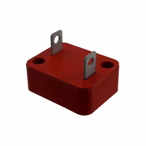
ICGOO电子元器件商城为您提供V251DB40由Littelfuse设计生产,在icgoo商城现货销售,并且可以通过原厂、代理商等渠道进行代购。 V251DB40价格参考。LittelfuseV251DB40封装/规格:TVS - 变阻器,MOV, 390V 40kA Varistor 1 Circuit Chassis Mount Blade Type, Encased。您可以下载V251DB40参考资料、Datasheet数据手册功能说明书,资料中有V251DB40 详细功能的应用电路图电压和使用方法及教程。
| 参数 | 数值 |
| 产品目录 | |
| 描述 | VARISTOR 354V 40KA BLADE ENCASED压敏电阻 250V 40kA 5000pF |
| 产品分类 | |
| 品牌 | Littelfuse |
| 产品手册 | |
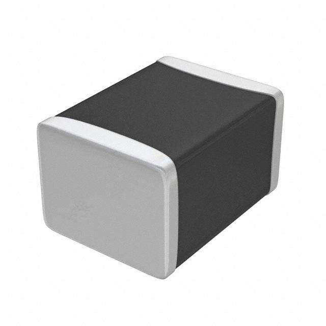
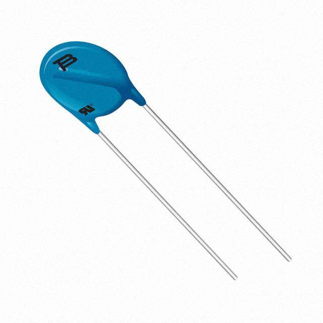
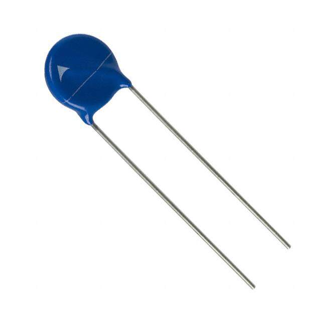
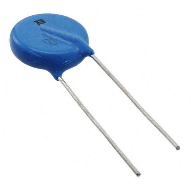
| 产品图片 |
|
| rohs | 符合RoHS无铅 / 符合限制有害物质指令(RoHS)规范要求 |
| 产品系列 | Littelfuse V251DB40DB |
| 数据手册 | |
| 产品型号 | V251DB40 |
| 产品培训模块 | http://www.digikey.cn/PTM/IndividualPTM.page?site=cn&lang=zhs&ptm=25313http://www.digikey.cn/PTM/IndividualPTM.page?site=cn&lang=zhs&ptm=25936 |
| 产品目录绘图 |
|
| 产品种类 | 压敏电阻 |
| 其它名称 | F3742 |
| 包装 | 散装 |
| 变阻器电压 | 354V |
| 商标 | Littelfuse |
| 外壳直径 | 40 mm |
| 安装 | SMD/SMT |
| 封装 | Bulk |
| 封装/外壳 | 插片式,有壳 |
| 尺寸 | 40 mm Dia. x 60.3 mm L x 12.7 mm H |
| 峰值浪涌电流 | 40 kA |
| 工作温度范围 | - 55 C to + 85 C |
| 工厂包装数量 | 10 |
| 最大AC电压 | 250VAC |
| 最大DC电压 | 330VDC |
| 标准包装 | 10 |
| 浪涌能量额定值 | 370 J |
| 电压额定值AC | 250 V |
| 电压额定值DC | 330 V |
| 电容 | 5000 pF |
| 电流-浪涌 | 40kA |
| 电路数 | 1 |
| 端接类型 | Screw |
| 系列 | DA / DB |
| 能量 | 370J |
| 钳位电压 | 650 V |




- 商务部:美国ITC正式对集成电路等产品启动337调查
- 曝三星4nm工艺存在良率问题 高通将骁龙8 Gen1或转产台积电
- 太阳诱电将投资9.5亿元在常州建新厂生产MLCC 预计2023年完工
- 英特尔发布欧洲新工厂建设计划 深化IDM 2.0 战略
- 台积电先进制程称霸业界 有大客户加持明年业绩稳了
- 达到5530亿美元!SIA预计今年全球半导体销售额将创下新高
- 英特尔拟将自动驾驶子公司Mobileye上市 估值或超500亿美元
- 三星加码芯片和SET,合并消费电子和移动部门,撤换高东真等 CEO
- 三星电子宣布重大人事变动 还合并消费电子和移动部门
- 海关总署:前11个月进口集成电路产品价值2.52万亿元 增长14.8%



PDF Datasheet 数据手册内容提取
Varistor Products Industrial High Energy Terminal Varistors > DA/DB Series DA/DB Varistor Series RoHS Description DA SERIES The DA and DB Series transient surge suppressors are heavy-duty industrial Metal-Oxide Varistors (MOVs) designed to provide surge protection for motor controls and power supplies used in oil- drilling, mining, and transportation equipment. These UL recognized varistors have identical ratings and specifications but differ in case construction to provide flexibility in equipment designs. DB SERIES DA Series devices feature rigid terminals to ensure secure wire contacts. Both the DA and DB Series feature improved creep and strike distance capability to minimize Agency Approvals breakdown along the package surface design that provides complete electrical isolation of the disc subassembly. Agency Agency File Number See DA/DB Series Device Ratings and Specifications E320116 table for part number and brand information. Features • RoHS compliant • Screw terminals (DA and Lead–free Series),quick connect push-on connectors • High energy (DB Series) absorption capability W up to 1050J • Case design provides TM complete electrical • Wide operating isolation of disc voltage range subassembly V 130V to 750V M(AC)RMS • 40mm diameter disc • No derating up to 85ºC ambient Ss ’e Vi r Absolute Maximum Ratings Oe MS • For ratings of individual members of a series, see Device Ratings and Specifications chart B Y Continuous DA/DB Series Units GD Steady State Applied Voltage: RA/ ED AC Voltage Range (VM(AC)RMS) 130 to 750 V N DC Voltage Range (V ) 175 to 970 V E M(DC) – Transients: I H Peak Pulse Current (I ) TM For 8/20μs Current Wave (See Figure 2) 40,000 A Single Pulse Energy Range For 2ms Current Squarewave (W ) 270 to 1050 J TM Operating Ambient Temperature Range (T) -55 to +85 ºC A Storage Temperature Range (T ) -55 to +125 ºC STG Temperature Coefficient (aV) of Clamping Voltage (V) at Specified Test Current <0.01 %/ºC C Hi-Pot Encapsulation (COATING Isolation Voltage Capability) 5000 V (Dielectric must withstand indicated DC voltage for one minute per MIL-STD 202, Method 301) COATING Insulation Resistance 1000 MΩ CAUTION: Stresses above those listed in "Absolute Maximum Ratings" may cause permanent damage to the device. This is a stress only rating and operation of the device at these or any other conditions above those indicated in the operational sections of this specification is not implied. ©2009 Littelfuse, Inc. DA/DB Varistor Series Specifications are subject to change without notice. Please refer to www.littelfuse.com/series/da or /db.html for current information. Revision: October 29, 2009
Varistor Products Industrial High Energy Terminal Varistors > DA/DB Series DA/DB Series Ratings & Specifications Maximum Rating (85ºC) Specifications (25ºC) Continuous Transient Maximum Typical Clamping DePvaircte N Burmanbdeirng VRMS VDC E(n2emrgs)y 8C uPx er2rae0knμ st VarisDtCor T Veostl tCaguerr eant t1mA 20V0(o8A/l 2tC V0uμCr sar)et nt tCa1naMpceaH cfzi -= V V W I Min V Max V C M(AC) M(DC) TM TM NOM C DA DB (V) (V) (J) (A) (V) (V) (V) (A) (pF) V131DA40 V131DB40 130 175 270 400001 184 200 228 345 10000 V151DA40 V151DB40 150 200 300 400002 212 240 268 405 8000 V251DA40 V251DB40 250 330 370 40000 354 390 429 650 5000 V271DA40 V271DB40 275 369 400 40000 389 430 473 730 4500 V321DA40 V321DB40 320 420 460 40000 462 510 561 830 3800 V421DA40 V421DB40 420 560 600 40000 610 680 748 1130 3000 V481DA40 V481DB40 480 640 650 40000 670 750 825 1240 2700 V511DA40 V511DB40 510 675 700 40000 735 820 910 1350 2500 V571DA40 V571DB40 575 730 770 40000 805 910 1000 1480 2200 V661DA40 V661DB40 660 850 900 40000 940 1050 1160 1720 2000 V751DA40 V751DB40 750 970 1050 40000 1080 1200 1320 2000 1800 Note : Average power dissipation of transients not to exceed 2.0W. Power Dissipation Ratings Peak Pulse Current Test Waveform E 100 100 U L LUE 9800 K VA 90 RATED VA 7600 OF PEA 50 F 50 T O N T 40 E N C PERCE 3200 PER 10 10 O1 T TIME 0 -55 50 60 70 80 90 100 110 120 130 140 15 T1 Figure 1 AMBIENT TEMPERATURE (oC) Figure 2 T2 NOTES: 1. Peak current Applies to applications rated up to 115VRMS. Peak current is 30kA for applications greater than 115V. 2. Peak current applies to applications rated up to 132VRMS. Peak 01 = Virtual Origin of Wave Current is 30kA for applications greater than 132V. T = Time from 10% to 90% of Peak T = Rise Time = 1.25 x T 1 Should transients occur in rapid succession, the T = Decay Time 2 average power dissipation required is simply the energy Example - For an 8/20 μs Current Waveform: (watt- seconds) per pulse times the number of pulses 8μs = T = Rise Time 1 per second. The power so developed must be within 20μs = T = Decay Time 2 the specifications shown on the Device Ratings and Specifications table for the specific device. Furthermore, the operating values need to be derated at high temperatures as shown above. Because varistors can only dissipate a relatively small amount of average power they are, therefore, not suitable for repetitive applications that involve substantial amounts of average power dissipation. DA/DB Varistor Series ©2009 Littelfuse, Inc. Specifications are subject to change without notice. Revision: October 29, 2009 Please refer to www.littelfuse.com/series/da or /db.html for current information.
Varistor Products Industrial High Energy Terminal Varistors > DA/DB Series Maximum Clamping Voltage Repetitive Surge Capability V131DA40 - V751DA40 and V131DB40 - V751DB40 V131DA40 - V751DA40 and V131DB40 - V751DB40 654,,,000000000 MD13IAS0X CTI OMS UI7ZM5E0 C 4V0LMmA(MmACP)IN RGA TVINOGLTAGEV751DA/DTBA4 =0 -55oC to 85oC 5200,,000000 1 210 VV1133D11IDDSBAC44 S00 I--Z VVE77 455011mDDmAB4400 V661DA/DB40 10,000 VOLTS (V) 32,,000000 V4V2V4158D111ADD/ADA/BD/D4B0B4400 V571DA/DB40 RENT (A) 521,,,000000000 110032 104105106 K R MUM PEA 1,987600000000000 URGE CU 520000 XI 500 S 100 A M 400 50 V151DA/DB40 V321DA/DB40 300 V271DA/DB40 20 INDEFINITE V131DA/DB40 V251DA/DB40 200 10 10-2 10-1 100 101 102 103 104 105 20 100 1,000 10,000 Figure 3 PEAK AMPERES (A) Figure 4 IMPULSE DURATION (μs) NOTE: If pulse ratings are exceeded, a shift of V (at specified current) of more than N(DC) +/-10% could result. This type of shift, which normally results in a decrease of V , may N(DC) result in the device not meeting the original published specifications, but it does not prevent the device from continuing to function, and to provide ample protection. Physical Specifications Environmental Specifications DA - Copper, Tin–plated Operating/Storage -55°C to +85°C/ -55°C to Lead Material DB - Brass, Tin–plated Temperature +125°C Cured, flame retardant epoxy polymer +85°C, 85% RH, 1000 hours Insulating Material meets UL94V–0 requirements. Humidity Aging +/- 5% typical resistance change Marked with LF, part number and date Device Labeling code +85°C to -40°C 10 times Thermal Shock +/- 5% typical resistance change Solvent Resistance MIL–STD–202, Method 215F Ss Moisture Sensitivity Level 1, J–STD–020C ’e Vi r Oe MS B Y D G RA/ ED N E – I H ©2009 Littelfuse, Inc. DA/DB Varistor Series Specifications are subject to change without notice. Please refer to www.littelfuse.com/series/da or /db.html for current information. Revision: October 29, 2009
Varistor Products Industrial High Energy Terminal Varistors > DA/DB Series Product Dimensions (mm) DA SERIES DB SERIES “A” DIMENSION: 60.3 ALL DIMENSIONS ARE MAXIMUM FILISTER HEAD SCREW - 51mm (2.01) (2.37) EXCEPT WHERE NOTED PAN HEAD SCREW - 53mm (2.09) 44.45 0.75 (1.75 0.03) A 4.3mm 15mm (0.59) (0.170) 46.8 25.4 0.75 (1.84) (1.00 0.03) 23mm 1mm M4 INTERNATIONAL (0.90 0.04) THREAD HOLES 0.23 THRU BORE 0.370 x 0.370 DP 12.7 40.5 (0.50) (1.6) 12.7 1.6 (0.50) 67mm (0.06) (2.64) 6.60 2 HOLES (0.26) 57mm 6.60 (2.24) (0.26) 41 23 (1.61) (0.90) 62mm (2.44) 4.5mm (0.18) Dimensions in millimeters and (inches). Part Numbering System V XX X DA 40 VARISTOR DISC SIZE (60mm) VVV MMM(((AAACCC))) SERIES DESIGNATOR First Tw o Significant Digits* DA or DB V M(AC) Decade Multiplier* *Refer to Rating & Specifications table Example: 130 VM(AC) = 131 DA/DB Varistor Series ©2009 Littelfuse, Inc. Specifications are subject to change without notice. Revision: October 29, 2009 Please refer to www.littelfuse.com/series/da or /db.html for current information.

 Datasheet下载
