
 Datasheet下载
- 型号: UWR-5/1600-D5A-C
- 制造商: Murata
- 库位|库存: xxxx|xxxx
- 要求:
| 数量阶梯 | 香港交货 | 国内含税 |
| +xxxx | $xxxx | ¥xxxx |
查看当月历史价格
查看今年历史价格
UWR-5/1600-D5A-C产品简介:
ICGOO电子元器件商城为您提供UWR-5/1600-D5A-C由Murata设计生产,在icgoo商城现货销售,并且可以通过原厂、代理商等渠道进行代购。 UWR-5/1600-D5A-C价格参考。MurataUWR-5/1600-D5A-C封装/规格:直流转换器, 隔离模块 DC/DC 转换器 1 输出 5V 1.6A 4.7V - 7.25V 输入。您可以下载UWR-5/1600-D5A-C参考资料、Datasheet数据手册功能说明书,资料中有UWR-5/1600-D5A-C 详细功能的应用电路图电压和使用方法及教程。
| 参数 | 数值 |
| 产品目录 | |
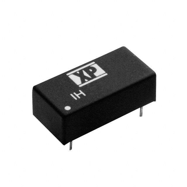
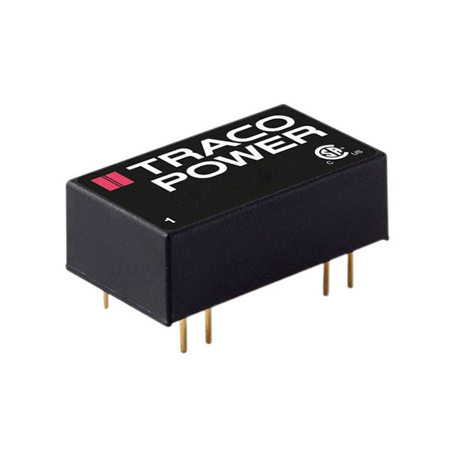
| 描述 | CONV DC/DC 5V 1600MA SGL A T/H隔离式DC/DC转换器 8W 5V to 5V 1600mA |
| 产品分类 | DC DC ConvertersDC/DC转换器 |
| 品牌 | Murata Power Solutions |
| 产品手册 | |
| 产品图片 |
|
| rohs | RoHS 合规性豁免无铅 / 符合限制有害物质指令(RoHS)规范要求 |
| 产品系列 | 隔离式DC/DC转换器,Murata Power Solutions UWR-5/1600-D5A-CUWR |
| 数据手册 | |
| 产品型号 | UWR-5/1600-D5A-C |
| 产品 | Isolated |
| 产品培训模块 | http://www.digikey.cn/PTM/IndividualPTM.page?site=cn&lang=zhs&ptm=21792 |
| 产品目录页面 | |
| 产品种类 | 隔离式DC/DC转换器 |
| 其它名称 | 811-1918-5 |
| 功率(W)-制造系列 | 8W |
| 功率(W)-最大值 | 8W |
| 包装 | 管件 |
| 商标 | Murata Power Solutions |
| 大小/尺寸 | 2.00" 长 x 1.00" 宽 x 0.38" 高(50.8mm x 25.4mm x 9.7mm) |
| 安装类型 | 通孔 |
| 封装 | Bulk |
| 封装/外壳 | 5-DIP 模块 |
| 工作温度 | -40°C ~ 70°C |
| 工厂包装数量 | 16 |
| 效率 | 76% |
| 标准包装 | 16 |
| 特性 | - |
| 电压-输入(最大值) | 7.25V |
| 电压-输入(最小值) | 4.7V |
| 电压-输出1 | 5V |
| 电压-输出2 | - |
| 电压-输出3 | - |
| 电压-隔离 | 1.5kV(1500V) |
| 电流-输出(最大值) | 1.6A |
| 类型 | 隔离模块 |
| 绝缘电压 | 1.5 kV |
| 输入电压范围 | 4.7 V to 7.25 V |
| 输出功率 | 8 W |
| 输出数 | 1 |
| 输出电压—通道1 | 5 V |
| 输出电流—通道1 | 1.6 A |
| 输出端数量 | 1 |
| 零件号别名 | UWR-5/1600-D5A-C |


- 商务部:美国ITC正式对集成电路等产品启动337调查
- 曝三星4nm工艺存在良率问题 高通将骁龙8 Gen1或转产台积电
- 太阳诱电将投资9.5亿元在常州建新厂生产MLCC 预计2023年完工
- 英特尔发布欧洲新工厂建设计划 深化IDM 2.0 战略
- 台积电先进制程称霸业界 有大客户加持明年业绩稳了
- 达到5530亿美元!SIA预计今年全球半导体销售额将创下新高
- 英特尔拟将自动驾驶子公司Mobileye上市 估值或超500亿美元
- 三星加码芯片和SET,合并消费电子和移动部门,撤换高东真等 CEO
- 三星电子宣布重大人事变动 还合并消费电子和移动部门
- 海关总署:前11个月进口集成电路产品价值2.52万亿元 增长14.8%


PDF Datasheet 数据手册内容提取
UWR Series www.murata-ps.com Single Output, High Reliability, 2" x 1", 6-10 Watt, DC-DC Converters FEATURES Low Cost! Highly reliable! Proven SMT-on-pcb construction PRODUCT OVERVIEW Designed to meet UL/EN/IEC 60950-1, CAN/CSA-C22.2 60950-1 Placing reliability and cost considerations above the intention of precipitating any potential electrical, all others, Murata Power Solutions' new A-Series DC/ mechanical or process weaknesses. Qual tested; HALT tested; EMC tested DC Converters combine straightforward circuit topolo- Packaged in 2" x 1" x 0.375" shielded metal Small packages, 2" x 1" x 0.375" gies, the newest components, proven SMT-on-pcb cases with non-conductive coatings, these fully Standard pinouts construction, and highly repeatable automatic assem- isolated (1500Vdc guaranteed) DC/DC’s offer excellent bly techniques. Considering the critical low-cost and line/load regulation, full I/O protection, and industry- 5, 5.2, 12 or 15 Volt outputs long-term-reliability requirements of today’s telecom, standard pinouts. Choice of 3 wide-range inputs: datacom and computer/networking applications, the Output voltages include 5, 5.2, 12 and 15 Volts. 4.7-7.25 Volts A-Series may well be the most cost-effective DC/DC’s Input voltage ranges are either 4.7-7.25V ("D5A" 9-18 Volts available today. models), 9-18V ("D12A" models) or 18-75V ("D48A" 18-75 Volts The single-output, 6-10 Watt Models of the models). All A-Series UWR models are fully EMI char- Fully isolated, 1500Vdc guaranteed A-Series deliver both high power densities and acterized and agency safety approved. impressive MTBF’s. Their superior durability is A-Series DC/DC’s are extremely reliable, easy- –40 to +100°C operation substantiated by a rigorous in-house qualifi cation pro- to-use, cost-effective power converters. Use them 5-side metal shielded cases with non- gram including HALT (Highly Accelerated Life Testing). to improve the reliability of existing equipment or to conductive baseplates The goal of HALT is not to simulate fi eld conditions but develop new systems that exceed design objectives. Modifi cations and customs for OEMs to expose devices to multiple excessive stresses with +VIN +VOUT (1) (3) COMMON (5) Typical topology is shown –VIN (2) PWM OPTO REFERENCE & CONTROLLER ISOLATION ERROR AMP Figure 1. Simplifi ed Schematic For full details go to www.murata-ps.com/rohs www.murata-ps.com/support MDC_UWR6-10W Series.E01 Page 1 of 6
UWR Series Single Output, High Reliability, 2" x 1", 6-10 Watt, DC-DC Converters Performance Specifi cations and Ordering Guide➀ Output Input ➁ Package VOUT * IOUT R/ N (mV p-p) Reg ulatio n (Ma x.) VIN Nom. Range IIN ➃ Effi ciency (Case, Root Model ➅ (Volts) (mA) Typ. Max. Line Load ➂ (Volts) (Volts) (mA) Min. Typ. Pinout) UWR-5/1600-D5A-C 5 1600 50 100 ±0.2% ±0.5% 5 4.7-7.25 20/2105 74% 76% C2, P11 UWR-5/2000-D24E-C ➄ 5 2000 50 75 ±0.2% ±0.5% 24 18-36 10/490 83% 85% C2, P11 UWR-5.2/1500-D5A-C 5.2 1500 50 100 ±0.2% ±0.5% 5 4.7-7.25 20/2053 74% 76% C2, P11 UWR-12/665-D5A-C 12 665 75 100 ±0.2% ±0.5% 5 4.7-7.25 25/2046 75% 78% C2, P11 UWR-12/830-D12A-C 12 830 75 100 ±0.2% ±0.5% 12 9-18 35/988 81% 84% C2, P11 UWR-5/1800-D48A-C 5 1800 75 100 ±0.1% ±0.25% 48 18-75 10/193 81% 83% C2, P11 UWR-5/2000-D12A-C 5 2000 50 75 ±0.2% ±0.5% 12 9-18 15/1029 79.5% 81% C2, P11 UWR-5/2000-D48E-C ➄ 5 2000 50 75 ±0.2% ±0.5% 48 36-72 10/248 82% 84% C2, P11 UWR-12/750-D48A-C 12 750 75 100 ±0.2% ±0.5% 48 18-75 10/230 81.5% 82.5% C2, P11 UWR-15/530-D5A-C 15 530 50 100 ±0.2% ±0.5% 5 4.7-7.25 40/2065 75% 77% C2, P11 UWR-15/600-D48A-C 15 600 75 100 ±0.2% ±0.5% 48 18-75 10/233 81.5% 84% C2, P11 UWR-15/665-D12A-C 15 665 75 100 ±0.2% ±0.5% 12 9-18 35/978 82% 85% C2, P11 ➀ Typical at TA = +25°C under nominal line voltage and full-load conditions unless otherwise noted. ➁ Ripple/Noise (R/N) measured over a 20MHz bandwidth. ➂ 10% to 100% load. ➃ Nominal line voltage, no-load/full-load conditions. ➄ See Technical Notes for an explanation of trading off input voltage ranges for higher full-power operating temperature. ➅ Please see the Part Number Structure for complete ordering options. PART NUMBER STRUCTURE MECHANICAL SPECIFICATIONS U WR - 5 / 1800 - D48 A - C 2.00 RoHS-6 hazardous Output Confi guration: (50.8) substance U = Unipolar compliant METAL CASE 0.375 Case C2 A-Series (9.5) Wide Range Input High Reliability INSULATED BASE Nominal Output Voltage: Input Voltage Range: 0.040 ±0.002 DIA. 5, 5.2, 12 or 15 Volts D5 = 4.7-7.25 Volts (5V nominal) 0.20 MIN (1.016 ±0.051) (5.1) D12 = 9-18 Volts (12V nominal) 0.800 0.60 Maximum Output D24 = 18-36 Volts (24V nominal) (20.3) (15.24) Current D48 = 18-75/36-72 Volts (48V nominal) in mA 3 0.100 Note: Some model number combinations may not be available. Contact Murata 1.00 1 4 (2.54) 0.800 Power Solutions for further information. (25.4) 2 (20.32) 0.400 (10.16) 5 TEMPERATURE DERATING 10 A, C 0.200 BOTTOM VIEW (5.08) 0.10 9 D, E C A (2.54) D 8 B I/O Connections Dimensions are in inches (mm) shown for ref. only. atts) 7 E Pin Function P11 Third Angle Projection W 1 +Vin er ( 6 2 –Vin w put Po 5 UUUWWWRRR---555///121806000000---DDD41582AAA BDC 34 N+oV oPuint Tolerances (unless otherwise specified): Out 4 UUWWRR--55//22000000--DD2448EE AA 5 Common ..XXXX X± ± 0 .00.20 1(00. 5(0).25) 3 UWR-5.2/1500-D5A B Angles ± 2˚ UWR-12/665-D5A B Notes: UWR-12/750-D48A E Components are shown for reference only. 2 UWR-12/830-D12A C For "D5A, D12A and D24E" models, UWR-15/530-D5A B UWR-15/600-D48A E the case is connected to 1 UWR-15/665-D12A C pin 2 (–VIN). 0 For "D48A and D48E" models, the case –40 0 40 45 50 55 60 65 70 75 80 85 90 95 100 is connected to pin 1 (+VIN). Ambient Temperature (°C) www.murata-ps.com/support MDC_UWR6-10W Series.E01 Page 2 of 6
UWR Series Single Output, High Reliability, 2" x 1", 6-10 Watt, DC-DC Converters Performance/Functional Specifi cations Typical @ TA = +25°C under nominal line voltage and full-load conditions, unless noted. ➀ Input Absolute Maximum Ratings Input Voltage Range: D5A Models 4.7-7.25 Volts (5V nominal) Input Voltage: D12A Models 9-18 Volts (12V nominal) D5A Models 10 Volts D24E Models 18-36Volts (24V nominal D12A Models 22 Volts D48A Models 18-75 Volts (48V nominal) D24E Models 44 Volts D48E Models 36-72 Volts (48V nominal) D48A and D48E Models 80 Volts Input Current See Ordering Guide Input Reverse-Polarity Protection Current must be <6A. Brief Input Filter Type ➁ Pi duration only. Fusing recommended. Output Overvoltage Protection Overvoltage Shutdown: 5/5.2V Outputs 6.8 Volts, limited duration D5A Models None 12V Outputs 15 Volts, limited duration D12A Models 20 Volts 15V Outputs 18 Volts, limited duration D24E Models 40 Volts D48A and D48E Models 76 Volts Output Current Current limited. Max. current and Reverse-Polarity Protection Yes (Instantaneous, 6A maximum) short-circuit duration model dependent. Output Storage Temperature –40 to +105°C VOUT Accuracy (50% load) ±1%, maximum Temperature Coeffi cient ±0.02% per °C Ripple/Noise (20MHz BW) ➁ See Ordering Guide These are stress ratings. Exposure of devices to greater than any of these conditions may adversely affect long-term reliability. Proper operation under conditions other than Line/Load Regulation See Ordering Guide those listed in the Performance/Functional Specifi cations Table is not implied. Effi ciency See Ordering Guide Isolation Voltage ➂ 1500Vdc, guaranteed Isolation Capacitance 250pF Current Limiting Auto-recovery TECHNICAL NOTES Overvoltage Protection ➃ Zener/transorb clamp, magnetic feedback Dynamic Characteristics Floating Outputs Transient Response (50% load step) 200µsec max. to ±1.5% of fi nal value Since these are isolated DC/DC converters, their outputs are "fl oating." Switching Frequency 165kHz (±15kHz) Designers will usually use the output Common (pin 5) as the ground/return Flammability UL94V-0 of the load circuit. You can, however, use the +Output (pin 3) as ground/ Environmental return to effectively reverse the output polarity. Operating Temperature (Ambient): Without Derating –40 to +60/65/70°C (Model dependent) Filtering and Noise Reduction With Derating to +100°C (See Derating Curves) All A-Series UWR 6-10 Watt DC/DC Converters achieve their rated ripple Storage Temperature –40 to +105°C and noise specifi cations without the use of external input/output capaci- Physical tors. In critical applications, input/output ripple and noise may be further Dimensions 2" x 1" x 0.375" (51 x 25 x 9.5mm) reduced by installing electrolytic capacitors across the input terminals and/ Shielding 5-sided or low-ESR tantalum or electrolytic capacitors across the output terminals. Case Connection: The caps should be located as close to the power converters as possible. D5A, D12A and D24E Models Pin 2 (–VIN) Typical values are listed in the tables below. In many applications, using D48A and D48E Models Pin 1 (+VIN) values greater than those listed will yield better results. Case Material Corrosion resistant steel with non-conductive, epoxy-based, black To Reduce Input Ripple enamel fi nish and plastic baseplate D5A Models 47µF, 10V Pin Material Gold plate over copper alloy D12A and D24E Models 20µF, 50V Weight 1.3 ounces (37 grams) D48A and D48E Models 10µF, 100V To Reduce Output Ripple 5/5.2V Outputs 47µF, 10V, Low ESR ➀ These power converters require a minimum 10% loading to maintain specifi ed regulation. Operation under no-load conditions will not damage these devices; however they may 12/15V Outputs 22µF, 20V, Low ESR not meet all listed specifi cations. ➁ Application-specifi c input/output fi ltering can be recommended and perhaps added In critical, space-sensitive applications, Murata Power Solutions may be internally upon request for scheduled, quantity orders. Contact Murata Power Solutions able to tailor the internal input/output fi ltering of these units to meet your Applications Engineering for details. ➂ Devices can be screened or modifi ed for higher guaranteed isolation voltages. specifi c requirements. Contact Murata Power Solutions Applications Engineering for details. ➃ Except for 3.3V devices which have no protection. www.murata-ps.com/support MDC_UWR6-10W Series.E01 Page 3 of 6
UWR Series Single Output, High Reliability, 2" x 1", 6-10 Watt, DC-DC Converters Typical Performance Curves (T = +25°C) A The performance curves below were derived from actual test data for a single model number (UWR-5/1800-D48A). Since all devices in the 6-10W UWR A-Series have the same circuit topology, the performance curves are representative of all devices. LINE REGULATION LOAD REGULATION Output Voltage vs. Input Voltage and Output Current Output Voltage vs. Output Current and Input Voltage 5.016 5.016 VIN = 18V 5.014 5.014 5.012 5.012 V (Volts)OUT 55..001008 IOUT = 0IO.9UTA = 0.18A V (Volts)OUT 55..001008 5.006 5.006 VIN = 72V 5.004 5.004 IOUT = 1.8A VIN = 48V 5.002 5.002 5.000 5.000 18 24 30 36 42 48 54 60 66 72 0.18 0.3 0.6 0.9 1.2 1.5 1.8 VIN (Volts) Output Current (Amps) EFFICIENCY Effi ciency vs. Output Current and Input Voltage 84 81 78 %) cy ( 75 VIN = 18V n e 72 Effici 69 VIN = 48V VIN = 72V 66 63 60 0.18 0.3 0.6 0.9 1.2 1.5 1.8 Output Current (Amps) www.murata-ps.com/support MDC_UWR6-10W Series.E01 Page 4 of 6
UWR Series Single Output, High Reliability, 2" x 1", 6-10 Watt, DC-DC Converters Input Fusing CUSTOM CAPABILITIES Certain applications and/or safety agencies may require the installation of Murata Power Solutions' world-class design, development and manu- fuses at the inputs of power conversion components. For Murata Power facturing team stands ready to work with you to deliver the exact power Solutions A-Series UWR 6-10 Watt DC/DC Converters, you should use slow- converter you need for your demanding, large volume, OEM applications. blow type fuses with values no greater than the following: And ... we’ll do it on time and within budget! V Range Fuse Value IN Our experienced applications and design staffs; quick-turn prototype D5A 3A capability; highly automated, SMT assembly facilities; and in-line SPC D12A and D24E 2A quality-control techniques combine to give us the unique ability to design D48A and D48E 1A and deliver any quantity of power converters to the highest standards of quality and reliability. EMI RADIATED EMISSIONS We have compiled a large library of DC/DC designs that are currently used If you’re designing with EMC in mind, please note that all of Murata Power in a variety of telecom, medical, computer, railway, aerospace and indus- Solutions' A-Series UWR 6-10 Watt DC/DC Converters have been character- trial applications. We may already have the converter you need. ized for radiated and conducted emissions in our new EMI/EMC labora- tory. Testing is conducted in an EMCO 5305 GTEM test cell utilizing EMCO Contact us. Our goal is to provide you the highest-quality, most cost- automated EMC test software. Radiated emissions are tested to the limits effective power converters available. of FCC Part 15, Class B and CISPR 22 (EN 55022), Class B. Radiated emis- Quality and Reliability sions plots to FCC and CISPR 22 for model UWR-12/665-D5A appear below. The A-Series are the fi rst DC/DC Converters to emerge from Murata Power Solutions' new, company-wide approach to designing and manufacturing the most reliable power converters available. The fi ve-pronged program draws our Quality Assurance function into all aspects of new-product UWR-12/665-D5A Radiated Emissions design, development, characterization, qualifi cation and manufacturing. FCC Part 15 Class B, 3 Meters Converter Output = 12Vdc @ 620mA Design for Reliability 80 Design for Reliability is woven throughout our multi-phased, new-product- 70 development process. Design-for-reliability practices are fully documented and begin early in the new-product development cycle with the following 60 M) FCC Class B Limit goals: V/ 50 Bµ 1. To work from an approved components/vendors list ensuring the use of d ns ( 40 reliable components and the rigorous qualifi cation of new components. o ssi 30 2. To design with safety margins by adhering to a strict set of derating mi d E 20 guidelines and performing theoretical worst-case analyses. diate 10 3. To locate potential design weaknesses early in the product-development Ra cycle by using extensive HALT (Highly Accelerated Life Testing). 0 Radiated Emissions 4. To prove that early design improvements are effective by employing a –10 thorough FRACA (Failure Reporting Analysis and Corrective Action) System. –20 100 1000 Soldering Guidelines Frequency (MHz) UWR-12/665-D5A Radiated Emissions Murata Power Solutions recommends the specifi cations below when installing these EN 55022 Class B, 10 Meters converters. These specifi cations vary depending on the solder type. Exceeding these Converter Output = 12Vdc @ 620mA specifi cations may cause damage to the product. Be cautious when there is high atmo- spheric humidity. We strongly recommend a mild pre-bake (100° C. for 30 minutes). Your 80 production environment may differ; therefore please thoroughly review these guidelines 70 with your process engineers. 60 M) Wave Solder Operations for through-hole mounted prod- V/ 50 dBµ EN 55022 Class B Limit ucts (THMT) ns ( 40 For Sn/Ag/Cu based solders: o missi 30 Maximum Preheat Temperature 115° C. d E 20 Maximum Pot Temperature 270° C. e Radiat 10 Maximum Solder Dwell Time 7 seconds 0 For Sn/Pb based solders: Radiated Emissions –10 Maximum Preheat Temperature 105° C. –20 Maximum Pot Temperature 250° C. 100 1000 Frequency (MHz) Maximum Solder Dwell Time 6 seconds www.murata-ps.com/support MDC_UWR6-10W Series.E01 Page 5 of 6
UWR Series Single Output, High Reliability, 2" x 1", 6-10 Watt, DC-DC Converters HALT Testing Qualifi cation The goal of the accelerated-stress techniques used by Murata Power For each new product, electrical performance is verifi ed via a comprehen- Solutions is to force device maturity, in a short period of time, by exposing sive characterization process and long-term reliability is confi rmed via a devices to excessive levels of "every stimulus of potential value." We use rigorous qualifi cation procedure. The qual procedure includes such strenu- HALT (Highly Accelerated Life Testing) repeatedly during the design and ous tests as thermal shock and 500 hour life. Qual testing is summarized early manufacturing phases to detect potential electrical and mechanical below. design weaknesses that could result in possible future fi eld failures. Qualifi cation Testing During HALT, prototype and pre-production DC/DC converters are sub- Qualifi cation Test Method/Comments jected to progressively higher stress levels induced by thermal cycling, HALT Murata Power Solutions in-house procedure rate of temperature change, vibration, power cycling, product-specifi c High Temperature Storage Max. rated temp., 1,000 hours stresses (such as dc voltage variation) and combined environments. The Thermal Shock 10 cycles, –55 to +125°C stresses are not meant to simulate fi eld environments but to expose any Temperature/Humidity +85°C, 85% humidity, 48 hours weaknesses in a product’s electro/mechanical design and/or assembly Lead Integrity Murata Power Solutions in-house procedure processes. The goal of HALT is to make products fail so that device weak- Life Test +70°C, 500 hours* nesses can be analyzed and strengthened as appropriate. Applied stresses Marking Permanency Murata Power Solutions in-house procedure are continually stepped up until products eventually fail. After corrective End Point Electrical Tests Per product specifi cation actions and/or design changes, stresses are stepped up again and the cycle is repeated until the "fundamental limit of the technology" is determined. * Interim electrical test at 200 hours. Murata Power Solutions has invested in a Qualmark OVS-1 HALT tester In-Line Process Controls and Screening capable of applying voltage and temperature extremes as well as 6-axis, A combination of statistical sampling and 100% inspection techniques linear and rotational, random vibration. A typical HALT profi le (shown above) keeps our assembly line under constant control. Parameters such as consists of thermal cycling (–55 to +125°C, 30°C/minute) and simultane- solder-paste thickness, component placement, cleanliness, etc. are statisti- ous, gradually increasing, random longitudinal and rotational vibration up cally sampled, charted and fi ne tuned as necessary. Visual inspections are to 20G’s with load cycling and applied-voltage extremes added as desired. performed by trained operators after pick-and-place, soldering and cleaning Many devices in Murata Power Solutions' new A-Series could not be made operations. Units are 100% electrically tested prior to potting. All devices to fail prior to reaching either the limits of the HALT chamber or some previ- are temperature cycled, burned-in, hi-pot tested and fi nal-electrical tested ously known physical limit of the device. prior to external visual examination, packing and shipping. We also use the HALT chamber and its ability to rapidly cool devices to verify their "cold-start" capabilities. Rapid Response to Problems 100 Murata Power Solutions employs an outstanding corrective-action system to immediately address any detected shortcomings in either products or 80 40 processes. Whenever our assembly, quality or engineering personnel spot 60 a product/process problem, or if a product is returned with a potential Temperature (°C) 4200 20 m Vibration (G's) duasensfdeeecmrtt,ab wklyee o cipmoermrraeetcidtoiinvae tte oal ycy tipieoelndrfs oo. rn mOe v oaef r d ttheimtea lieole, wdthe fisast i lspuyrrsoetd eaumnca thl ydasesif seh caetnl pdrea, dtief rsne eifin cn etehs eos uarr y, 0 0 Rando industry. –20 –40 10 20 30 40 50 60 70 80 90 Test Time (minutes) Typical HALT Profi le This product is subject to the following operating requirements Murata Power Solutions, Inc. and the Life and Safety Critical Application Sales Policy: 11 Cabot Boulevard, Mansfi eld, MA 02048-1151 U.S.A. Refer to: http://www.murata-ps.com/requirements/ ISO 9001 and 14001 REGISTERED Murata Power Solutions, Inc. makes no representation that the use of its products in the circuits described herein, or the use of other technical information contained herein, will not infringe upon existing or future patent rights. The descriptions contained herein do not imply the granting of licenses to make, use, or sell equipment constructed in accordance therewith. Specifi cations are subject to change without notice. © 2015 Murata Power Solutions, Inc. www.murata-ps.com/support MDC_UWR6-10W Series.E01 Page 6 of 6
Mouser Electronics Authorized Distributor Click to View Pricing, Inventory, Delivery & Lifecycle Information: M urata: UWR-12/665-D5A-C UWR-5.2/1500-D5A-C UWR-5/1600-D5A-C UWR-5/1800-D48A-C UWR-5/2000-D12A-C UWR-5/2000-D24E-C