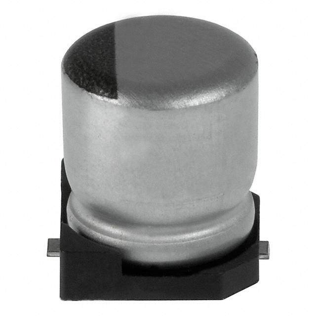
- 型号: UWD1H100MCL1GS
- 制造商: Nichicon
- 库位|库存: xxxx|xxxx
- 要求:
| 数量阶梯 | 香港交货 | 国内含税 |
| +xxxx | $xxxx | ¥xxxx |
查看当月历史价格
查看今年历史价格
UWD1H100MCL1GS产品简介:
ICGOO电子元器件商城为您提供UWD1H100MCL1GS由Nichicon设计生产,在icgoo商城现货销售,并且可以通过原厂、代理商等渠道进行代购。 UWD1H100MCL1GS价格参考。NichiconUWD1H100MCL1GS封装/规格:铝电解电容器, 10µF 50V 铝电解电容器 径向,Can - SMD 105°C 时为 2000 小时。您可以下载UWD1H100MCL1GS参考资料、Datasheet数据手册功能说明书,资料中有UWD1H100MCL1GS 详细功能的应用电路图电压和使用方法及教程。
Nichicon UWD1H100MCL1GS 是一款铝电解电容器,具有高耐纹波电流和长寿命的特点。其主要应用场景包括但不限于以下几个方面:

1. 电源电路:该电容器适用于各种开关电源(SMPS)、线性电源以及直流-直流转换器等电源设备中。它能够有效滤除电源中的纹波,稳定输出电压,确保电子设备的正常运行。例如,在服务器、通信基站、工业控制系统的电源模块中,UWD1H100MCL1GS 可以提供可靠的滤波和储能功能。

2. 音频设备:在音响系统、功放、耳机放大器等音频设备中,UWD1H100MCL1GS 可用于耦合、去耦及旁路电路,减少噪声干扰,提升音质表现。它的低ESR(等效串联电阻)特性有助于改善动态响应,使声音更加清晰、纯净。

3. 电机驱动:对于变频器、伺服驱动器等电机控制系统,该电容器可以承受较大的纹波电流,确保电机平稳运行。同时,其长寿命设计也减少了维护成本和停机时间,特别适合于工业自动化、机器人等领域。

4. 汽车电子:在现代汽车的电子系统中,如车载充电器、LED照明、娱乐系统等,UWD1H100MCL1GS 可以应对复杂的电气环境,具备良好的温度特性和抗振性能,保障车辆电子设备的可靠性。

5. 消费电子产品:在电视、显示器、笔记本电脑等消费类电子产品中,这款电容器可用于电源管理和信号调理电路,确保产品在长时间使用下的稳定性和耐用性。

总之,Nichicon UWD1H100MCL1GS 凭借其卓越的电气性能和可靠性,广泛应用于各类需要高性能电容器的领域,特别是在对稳定性要求较高的工业和高端消费市场中表现出色。
| 参数 | 数值 |
| 产品目录 | |
| 描述 | CAP ALUM 10UF 50V 20% SMD铝质电解电容器-SMD 50volts 10uF 6.3x5.8 |
| ESR(等效串联电阻) | - |
| 产品分类 | |
| 品牌 | Nichicon |
| 产品手册 | |
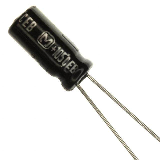
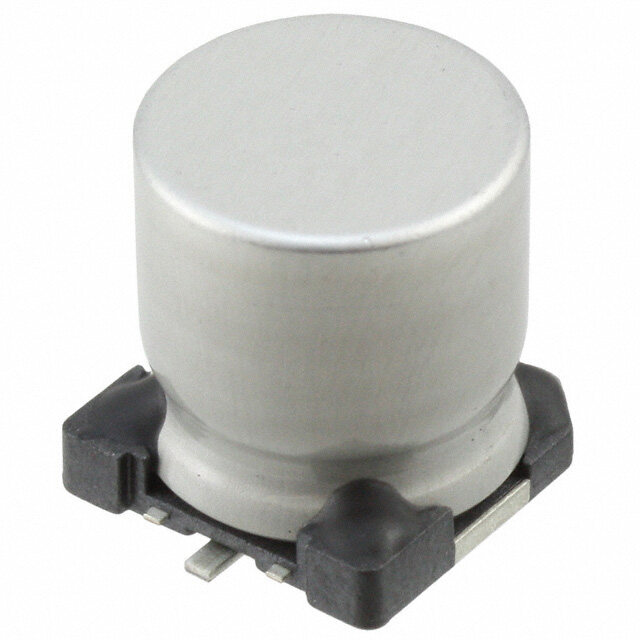
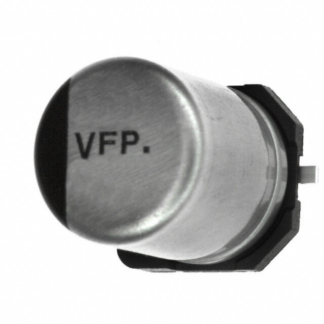
| 产品图片 |
|
| rohs | 符合RoHS无铅 / 符合限制有害物质指令(RoHS)规范要求 |
| 产品系列 | 铝电解电容器,铝质电解电容器-SMD,Nichicon UWD1H100MCL1GSWD |
| 数据手册 | |
| 产品型号 | UWD1H100MCL1GS |
| 不同温度时的使用寿命 | 105°C 时为 2000 小时 |
| 产品 | Low Impedance Electrolytic Capacitors |
| 产品种类 | 铝质电解电容器-SMD |
| 其它名称 | 493-6294-6 |
| 加载寿命 | 2000 h |
| 包装 | Digi-Reel® |
| 商标 | Nichicon |
| 外壳直径 | 6.3 mm |
| 外壳长度 | 5.8 mm |
| 大小/尺寸 | 0.248" 直径(6.30mm) |
| 安装类型 | 表面贴装 |
| 容差 | 20 % |
| 封装 | Reel |
| 封装/外壳 | 径向,Can - SMD |
| 工作温度 | -55°C ~ 105°C |
| 工厂包装数量 | 1000 |
| 应用 | 通用 |
| 引线间距 | - |
| 损耗因数DF | 0.12 |
| 最大工作温度 | + 105 C |
| 最小工作温度 | - 55 C |
| 标准包装 | 1 |
| 漏泄电流 | 3 uA |
| 电压额定值DC | 50 V |
| 电容 | 10 uF |
| 端接类型 | SMD/SMT |
| 类型 | Chip Type, Low Impedance |
| 系列 | WD |
| 纹波电流 | 165 mA |
| 表面贴装焊盘尺寸 | 0.260" 长 x 0.260" 宽(6.60mm x 6.60mm) |
| 阻抗 | 880 毫欧 |
| 额定电压 | 50V |
| 高度-安装(最大值) | 0.240"(6.10mm) |
PDF Datasheet 数据手册内容提取
ALUMINUM ELECTROLYTIC CAPACITORS UWD Chip Type, Low Impedance High Temperature (260°C) Reflow Corresponding with 260°C peak reflow soldering Recomended reflow condition : 260°C peak 5 sec. 230°C over 60 sec. 2 times (φ10 × 10 : 1 time) UWD Chip type, low impedance temperature range up to +105°C. Designed for surface mounting on high density PC board. Applicable to automatic mounting machine fed with carrier tape. Compliant to the RoHS directive (2011/65/EU). High Temperature AEC-Q200 compliant. Please contact us for details. Reflow UUD Specifications Item Performance Characteristics Category Temperature Range –55 to +105°C Rated Voltage Range 6.3 to 50V Rated Capacitance Range 1 to 1500µF Capacitance Tolerance ±20% at 120Hz, 20°C Leakage Current After 2 minutes' application of rated voltage at 20°C, leakage current is not more than 0.01 CV or 3 (µA), whichever is greater. Measurement frequency : 120Hz at 20°C Tangent of loss angle (tan δ) Rated voltage (V) 6.3 10 16 25 35 50 tan δ (MAX.) 0.26 (0.28) 0.20 (0.24) 0.16 (0.20) 0.14 (0.16) 0.12 (0.14) 0.12 (0.14) ( ) is φ8 over Measurement frequency : 120Hz Rated voltage (V) 6.3 10 16 25 35 50 Stability at Low Temperature Impedance ratio Z–25°C / Z+20°C 3 2 2 2 2 2 ZT / Z20 (MAX.) Z–55°C / Z+20°C 5 4 4 3 3 3 The specifications listed at right shall be met Capacitance change Within ±30% of the initial capacitance value when the capacitors are restored to 20°C after the Endurance tan δ 200% or less than the initial specified value rated voltage is applied for 5000 hours (2000 Leakage current Less than or equal to the initial specified value hours for φD = 4, 5 and 6.3) at 105°C. After storing the capacitors under no load at 105°C for 1000 hours and then performing voltage treatment based on JIS C 5101-4 Shelf Life clause 4.1 at 20°C, they shall meet the specified values for the endurance characteristics listed above. The capacitors are kept on a hot plate for 30 seconds, which is Capacitance change Within ±10% of the initial capacitance value Resistance to soldering maintained at 250°C. The capacitors shall meet the characteristic heat requirements listed at right when they are removed from the plate tan δ Less than or equal to the initial specified value and restored to 20°C. Leakage current Less than or equal to the initial specified value Marking Black print on the case top. Chip Type Type numbering system (Example : 16V 22µF) (φ4 to φ6.3) Positive 1 2 3 4 5 6 7 8 9 10 11 12 13 14 Plastic platform UWD 1 C 2 2 0 M C L 1 G S Voltage (C:16V) Series 0.3MAX. C±0.2 MAX. 0.5 A233CWD D±0.5φ B±0.2 A±0.2A±0.2E Capacitance tolPCearoacnnkfcaiegg ue(±r ac2ot0ido%en) Lot No. Capacitance L±0.3 H Negative Rated capacitance (22µF) Rated voltage (16V) Series name Type (φ8,φ10) Positive Plastic platform VTorlatadgee m (aVr:k35V) Series 0.3MAX. C±0.2 0.5MAX. φ D × L 4 × 5.8 5 × 5.8 6.3 × 5.8 6.3 × 7.7 8 × 10 10 × (1m0m) A2100VWD D±0.5φ B±0.2 A±0.2A±0.2E CABEL 14415.....83308 25515.....13338 26625.....46628 26627.....46627 28831....09331 1134100..02..533 Lot No. Capacitance L±0.5 H Negative H 0.5 to 0.8 0.5 to 0.8 0.5 to 0.8 0.5 to 0.8 0.8 to 1.1 0.8 to 1.1 Voltage V 6.3 10 16 25 35 50 Code j A C E V H Dimension table in next page. 143 CAT.8100H
ALUMINUM ELECTROLYTIC CAPACITORS UWD Dimensions V 6.3 10 16 25 35 50 Cap. (µF) Code 0J 1A 1C 1E 1V 1H 1 010 4 × 5.8 5.00 30 2.2 2R2 4 × 5.8 5.00 30 3.3 3R3 4 × 5.8 5.00 30 4.7 4R7 4 × 5.8 1.80 80 5 × 5.8 1.52 85 10 100 4 × 5.8 1.80 80 5 × 5.8 0.76 150 6.3 × 5.8 0.88 165 15 150 4 × 5.8 1.80 80 5 × 5.8 0.76 150 5 × 5.8 0.76 150 6.3 × 5.8 0.88 165 22 220 4 × 5.8 1.80 80 5 × 5.8 0.76 150 5 × 5.8 0.76 150 5 × 5.8 0.76 150 6.3 × 5.8 0.88 165 27 270 4 × 5.8 1.80 80 5 × 5.8 0.76 150 5 × 5.8 0.76 150 6.3 × 5.8 0.44 230 6.3 × 5.8 0.44 230 6.3 × 7.7 0.68 185 33 330 5 × 5.8 0.76 150 5 × 5.8 0.76 150 6.3 × 5.8 0.44 230 6.3 × 5.8 0.44 230 6.3 × 5.8 0.44 230 6.3 × 7.7 0.68 185 47 470 5 × 5.8 0.76 150 6.3 × 5.8 0.44 230 6.3 × 5.8 0.44 230 6.3 × 5.8 0.44 230 6.3 × 5.8 0.44 230 6.3 × 7.7 0.68 185 56 560 5 × 5.8 0.76 150 6.3 × 5.8 0.44 230 6.3 × 5.8 0.44 230 6.3 × 5.8 0.44 230 6.3 × 7.7 0.34 280 8 × 10 0.34 300 68 680 6.3 × 5.8 0.44 230 6.3 × 5.8 0.44 230 6.3 × 5.8 0.44 230 6.3 × 5.8 0.44 230 6.3 × 7.7 0.34 280 8 × 10 0.34 300 100 101 6.3 × 5.8 0.44 230 6.3 × 5.8 0.44 230 6.3 × 5.8 0.44 230 6.3 × 7.7 0.34 280 8 × 10 0.17 450 8 × 10 0.34 300 150 151 6.3 × 5.8 0.44 230 6.3 × 5.8 0.44 230 6.3 × 7.7 0.34 280 8 × 10 0.17 450 8 × 10 0.17 450 10 × 10 0.18 670 220 221 6.3 × 5.8 0.44 230 6.3 × 7.7 0.34 280 6.3 × 7.7 0.34 280 8 × 10 0.17 450 10 × 10 0.09 670 10 × 10 0.18 670 330 331 6.3 × 7.7 0.34 280 8 × 10 0.17 450 8 × 10 0.17 450 10 × 10 0.09 670 10 × 10 0.09 670 470 471 8 × 10 0.17 450 8 × 10 0.17 450 8 × 10 0.17 450 10 × 10 0.09 670 680 681 8 × 10 0.17 450 10 × 10 0.09 670 10 × 10 0.09 670 1000 102 10 × 10 0.09 670 10 × 10 0.09 670 Case size Rated 1500 152 10 × 10 0.09 670 φD × L (mm) Impedance ripple Max. Impedance (Ω) at 20°C 100kHz, Rated ripple current (mArms) at 105°C 100kHz Frequency coefficient of rated ripple current Frequency 50 Hz 120 Hz 300 Hz 1 kHz 10 kHz or more Coefficient 0.35 0.50 0.64 0.83 1.00 Taping specifications are given in page 23. Recommended land size, soldering by reflow are given in page 18, 19. Please refer to page 3 for the minimum order quantity. 144 CAT.8100H
Mouser Electronics Authorized Distributor Click to View Pricing, Inventory, Delivery & Lifecycle Information: N ichicon: UWD0J101MCL1GS UWD0J102MCL1GS UWD0J151MCL1GS UWD0J152MCL1GS UWD0J221MCL1GS UWD0J270MCL1GS UWD0J330MCL1GS UWD0J331MCL1GS UWD0J470MCL1GS UWD0J471MCL1GS UWD0J560MCL1GS UWD0J680MCL1GS UWD0J681MCL1GS UWD1A101MCL1GS UWD1A102MCL1GS UWD1A151MCL1GS UWD1A220MCL1GS UWD1A221MCL1GS UWD1A270MCL1GS UWD1A330MCL1GS UWD1A331MCL1GS UWD1A470MCL1GS UWD1A471MCL1GS UWD1A560MCL1GS UWD1A680MCL1GS UWD1A681MCL1GS UWD1C101MCL1GS UWD1C150MCL1GS UWD1C151MCL1GS UWD1C220MCL1GS UWD1C221MCL1GS UWD1C270MCL1GS UWD1C330MCL1GS UWD1C331MCL1GS UWD1C470MCL1GS UWD1C471MCL1GS UWD1C560MCL1GS UWD1C680MCL1GS UWD1C681MCL1GS UWD1E100MCL1GS UWD1E101MCL1GS UWD1E150MCL1GS UWD1E151MCL1GS UWD1E220MCL1GS UWD1E221MCL1GS UWD1E270MCL1GS UWD1E330MCL1GS UWD1E331MCL1GS UWD1E470MCL1GS UWD1E471MCL1GS UWD1E560MCL1GS UWD1E680MCL1GS UWD1H010MCL1GS UWD1H100MCL1GS UWD1H101MCL1GS UWD1H150MCL1GS UWD1H151MCL1GS UWD1H2R2MCL1GS UWD1H220MCL1GS UWD1H221MCL1GS UWD1H270MCL1GS UWD1H3R3MCL1GS UWD1H330MCL1GS UWD1H4R7MCL1GS UWD1H470MCL1GS UWD1H560MCL1GS UWD1H680MCL1GS UWD1V100MCL1GS UWD1V101MCL1GS UWD1V150MCL1GS UWD1V151MCL1GS UWD1V220MCL1GS UWD1V221MCL1GS UWD1V270MCL1GS UWD1V330MCL1GS UWD1V331MCL1GS UWD1V4R7MCL1GS UWD1V470MCL1GS UWD1V560MCL1GS UWD1V680MCL1GS UUX2G4R7MNL1GS UWD1V221MCQ6GS UWD1H220MCQ1GS UWD1V101MCQ1GS UWD1H221MCQ1GS UWD1V220MCQ1GS UWD1V221MCQ1GS
 Datasheet下载
