- 型号: UVZ1V100MDD
- 制造商: Nichicon
- 库位|库存: xxxx|xxxx
- 要求:
| 数量阶梯 | 香港交货 | 国内含税 |
| +xxxx | $xxxx | ¥xxxx |
查看当月历史价格
查看今年历史价格
UVZ1V100MDD产品简介:
ICGOO电子元器件商城为您提供UVZ1V100MDD由Nichicon设计生产,在icgoo商城现货销售,并且可以通过原厂、代理商等渠道进行代购。 UVZ1V100MDD价格参考。NichiconUVZ1V100MDD封装/规格:铝电解电容器, 10µF 35V 铝电解电容器 径向,Can 105°C 时为 1000 小时。您可以下载UVZ1V100MDD参考资料、Datasheet数据手册功能说明书,资料中有UVZ1V100MDD 详细功能的应用电路图电压和使用方法及教程。
| 参数 | 数值 |
| 产品目录 | |
| 描述 | CAP ALUM 10UF 35V 20% RADIAL铝质电解电容器 - 带引线 35volts 10uF 105c |
| ESR(等效串联电阻) | - |
| 产品分类 | |
| 品牌 | Nichicon |
| 产品手册 | |
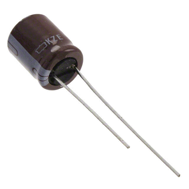
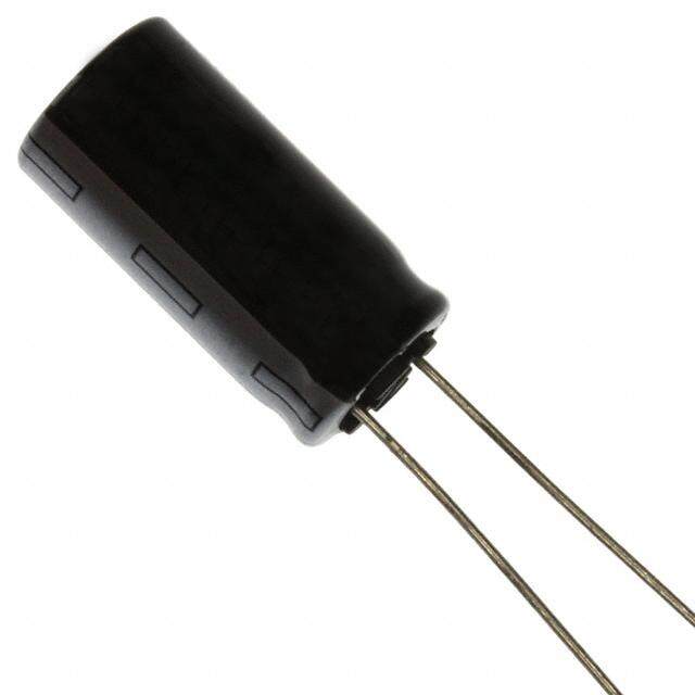
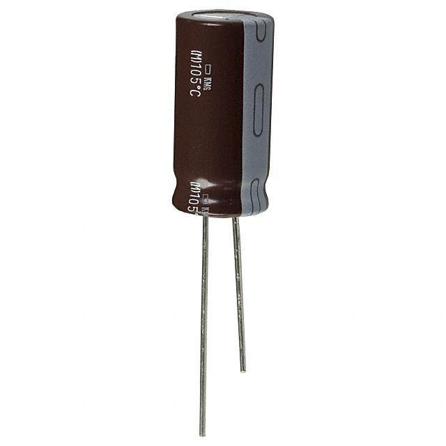
| 产品图片 |
|
| rohs | 符合RoHS无铅 / 符合限制有害物质指令(RoHS)规范要求 |
| 产品系列 | 铝电解电容器,铝质电解电容器 - 带引线,Nichicon UVZ1V100MDDVZ |
| 数据手册 | |
| 产品型号 | UVZ1V100MDD |
| 不同温度时的使用寿命 | 105°C 时为 1000 小时 |
| 产品 | General Purpose Electrolytic Capacitors |
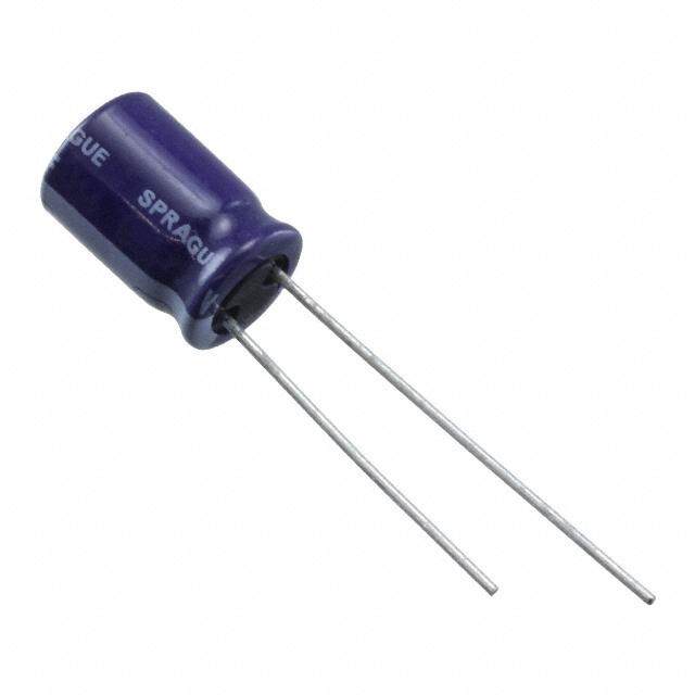
| 产品目录绘图 |
|
| 产品目录页面 | |
| 产品种类 | 铝质电解电容器 - 带引线 |
| 其它名称 | 493-1314 |
| 加载寿命 | 1000 h |
| 包装 | 散装 |
| 商标 | Nichicon |
| 外壳直径 | 5 mm |
| 外壳长度 | 11 mm |
| 大小/尺寸 | 0.197" 直径(5.00mm) |
| 安装类型 | 通孔 |
| 容差 | 20 % |
| 封装 | Bulk |
| 封装/外壳 | 径向,Can |
| 尺寸 | 5 mm Dia. x 11 mm L |
| 工作温度 | -55°C ~ 105°C |
| 工厂包装数量 | 200 |
| 应用 | 通用 |
| 引线间距 | 0.079"(2.00mm) |
| 引线间隔 | 2 mm |
| 损耗因数DF | 0.14 |
| 最大工作温度 | + 105 C |
| 标准包装 | 200 |
| 漏泄电流 | 10.5 uA |
| 电压额定值DC | 35 V |
| 电容 | 10 uF |
| 端接类型 | Radial |
| 类型 | Wide Temperature Range Aluminum Electrolytic Capacitors |
| 系列 | VZ |
| 纹波电流 | 41 mA |
| 表面贴装焊盘尺寸 | - |
| 设计资源 | |
| 阻抗 | - |
| 额定电压 | 35V |
| 高度-安装(最大值) | 0.433"(11.00mm) |



- 商务部:美国ITC正式对集成电路等产品启动337调查
- 曝三星4nm工艺存在良率问题 高通将骁龙8 Gen1或转产台积电
- 太阳诱电将投资9.5亿元在常州建新厂生产MLCC 预计2023年完工
- 英特尔发布欧洲新工厂建设计划 深化IDM 2.0 战略
- 台积电先进制程称霸业界 有大客户加持明年业绩稳了
- 达到5530亿美元!SIA预计今年全球半导体销售额将创下新高
- 英特尔拟将自动驾驶子公司Mobileye上市 估值或超500亿美元
- 三星加码芯片和SET,合并消费电子和移动部门,撤换高东真等 CEO
- 三星电子宣布重大人事变动 还合并消费电子和移动部门
- 海关总署:前11个月进口集成电路产品价值2.52万亿元 增长14.8%

PDF Datasheet 数据手册内容提取
ALUMINUM ELECTROLYTIC CAPACITORS UVZ Wide Temperature Range (Through 100V only) Small case sizes as same as UVR, but operating over wide temperature range of –55 to +105˚C. Compliant to the RoHS directive (2011/65/EU). UPS High Rippie Current UVZ High Reliability UPJ Smaller High Temperature UVY UVR Specifications Item Performance Characteristics Category Temperature Range –55 to +105˚C (6.3 to 100V) , –40 to +105˚C (160 to 400V), –25 to +105˚C (450V) Rated Voltage Range 6.3 to 450V Rated Capacitance Range 0.47 to 33000µF Capacitance Tolerance ±20% at 120Hz, 20˚C Rated voltage (V) 6.3 to 100 160 to 450 After 1 minute's application of rated voltage at 20°C, leakage current After 1 minute's application of rated voltage at 20°C, Leakage Current is not more than 0.03CV or 4 (µA), whichever is greater. CV <= 1000 : I = 0.1CV+40 (µA) or less After 2 minutes' application of rated voltage at 20°C, leakage current After 1 minute's application of rated voltage at 20°C, is not more than 0.01CV or 3 (µA), whichever is greater. CV > 1000 : I = 0.04CV+100 (µA) or less For capacitance of more than 1000µF, add 0.02 for every increase of 1000µF. Measurement frequency : 120Hz at 20˚C Tangent of loss angle (tan δ) Rated voltage (V) 6.3 10 16 25 35 50 63 100 160 to 315 350 to 450 tan δ (MAX.) 0.28 0.24 0.20 0.16 0.14 0.12 0.10 0.08 0.20 0.25 Measurement frequency : 120Hz Rated voltage (V) 6.3 10 16 25 35 50 63 100 160 to 200250 to 350 400 450 Stability at Low Temperature Impedance ratio Z–25˚C / Z+20˚C 5 4 3 2 2 2 2 2 3 4 6 15 ZT / Z20 (MAX.) Z–40˚C / Z+20˚C 10 8 6 4 3 3 3 3 4 8 10 — The specifications listed at right shall be met when Capacitance change Within ±20% of the initial capacitance value Endurance the capacitors are restored to 20°C after the rated tan δ 200% or less than the initial specified value voltage is applied for 1000 hours at 105°C. Leakage current Less than or equal to the initial specified value After storing the capacitors under no load at 105˚C for 1000 hours and then performing voltage treatment based on JIS C 5101-4 Shelf Life clause 4.1 at 20°C, they shall meet the specified values for the endurance characteristics listed above. Marking Printed with white color letter on black sleeve. Radial Lead Type Type numbering system (Example : 10V 330µF) Sleeve (P.E.T.) φd 1 2 3 4 5 6 7 8 9 10 11 U V Z 1 A 3 3 1 M E D Configuration + MAXD ±0.5P CapRaactietadn ccaep taocleitraannccee ( (3±3200µ%F)) φ Rated voltage (10V) Series name Pressure relief vent (φ6.3up) L+ MAX 15MIN 4MIN Type Configuration (mm) φD 5 6.3 8 10 12.5 16 18 20 22 25 φ D PPbb--ffrreeee lPeEadTw silreeeve P 2.0 2.5 3.5 5.0 5.0 7.5 7.5 10.0 10.0 12.5 5 DD φd 0.5 0.5 0.6 0.6 0.6 0.8 0.8 1.0 1.0 1.0 6.3 ED 0.5 0.5 0.5 0.5 0.5 0.5 0.5 0.5 1.0 1.0 8 · 10 PD 12.5 to 18 HD (L 20) 1.5 20 to 25 RD (L 20) 2.0 • Please refer to page 20 about the end seal configuration. Please refer to page 20, 21, 22 about the formed or taped product spec. Please refer to page 4 for the minimum order quantity. Dimension table in next page. 188 CAT.8100H
ALUMINUM ELECTROLYTIC CAPACITORS UVZ Dimensions V 6.3 10 16 25 35 50 Cap.(µF) Code 0J 1A 1C 1E 1V 1H 2.2 2R2 5 5 × 11.5 20 3.3 3R3 5 × 11.5 25 4.7 4R7 5 × 11.5 25 5 × 11.5 28 5 × 11.5 30 10 100 5 × 11.5 35 5 × 11.5 36 5 × 11.5 41 5 × 11.5 46 22 220 5 × 11.5 45 5 × 11.5 45 5 × 11.5 54 5 × 11.5 58 5 × 11.5 61 5 × 11.5 68 33 330 5 × 11.5 55 5 × 11.5 58 5 × 11.5 65 5 × 11.5 68 5 × 11.5 75 5 × 11.5 90 47 470 5 × 11.5 65 5 × 11.5 68 5 × 11.5 79 5 × 11.5 83 5 × 11.5 93 6.3 × 11.5 115 100 101 5 × 11.5 95 5 × 11.5 105 5 × 11.5 115 6.3 × 11.5 140 6.3 × 11.5 150 8 × 11.5 190 220 221 5 × 11.5 145 6.3 × 11.5 175 6.3 × 11.5 190 8 × 11.5 240 10 × 12.5 275 10 × 12.5 300 330 331 6.3 × 11.5 195 6.3 × 11.5 210 8 × 11.5 265 10 × 12.5 315 10 × 12.5 350 10 × 16.5 410 470 471 6.3 × 11.5 230 6.3 × 11.5 250 8 × 11.5 315 10 × 12.5 380 10 × 16.5 460 12.5 × 20.5 530 1000 102 8 × 11.5 390 10 × 12.5 460 10 × 16.5 560 10 × 20.5 680 12.5 × 20.5 810 12.5 × 25.5 950 2200 222 10 × 20.5 710 10 × 20.5 760 12.5 × 20.5 920 12.5 × 25.5 1090 16 × 25.5 1260 16 × 35.5 1470 3300 332 10 × 20.5 840 12.5 × 20.5 1000 12.5 × 25.5 1170 16 × 25.5 1400 16 × 35.5 1610 18 × 35.5 1770 4700 472 12.5 × 20.5 1090 12.5 × 25.5 1260 16 × 25.5 1480 16 × 31.5 1710 18 × 35.5 1910 20 × 40.5 2100 6800 682 12.5 × 25.5 1350 16 × 25.5 1570 16 × 35.5 1780 18 × 35.5 2040 20 × 40.5 2150 22 × 50.5 2500 10000 103 16 × 25.5 1650 16 × 35.5 1890 18 × 35.5 2060 20 × 40.5 2150 22 × 50.5 2650 25 × 50.5 2850 15000 153 16 × 35.5 2010 18 × 35.5 2180 20 × 40.5 2430 22 × 50.5 2750 25 × 50.5 3100 22000 223 18 × 40.5 2350 20 × 40.5 2650 22 × 50.5 3000 25 × 50.5 3250 Case size Rated 33000 333 22 × 50.5 2800 22 × 50.5 3250 25 × 50.5 3450 φD × L (mm) ripple V 63 100 160 200 250 315 350 400 450 Cap.(µF) Code 1J 2A 2C 2D 2E 2F 2V 2G 2W 0.47 R47 6.3 × 11.5 11 6.3 × 11.5 11 6.3 × 11.5 10 1 010 6.3 × 11.5 16 6.3 × 11.5 16 6.3 × 11.5 15 6.3 × 11.5 15 6.3 × 11.5 15 8 × 11.5 17 8 × 11.5 13 2.2 2R2 5 × 11.5 21 6.3 × 11.5 25 6.3 × 11.5 25 6.3 × 11.5 23 8 × 11.5 26 8 × 11.5 26 10 × 12.5 30 10 × 12.5 23 3.3 3R3 5 × 11.5 29 6.3 × 11.5 30 6.3 × 11.5 30 8 × 11.5 32 10 × 12.5 38 10 × 12.5 38 10 × 12.5 38 10 × 16.5 31 4.7 4R7 5 × 11.5 32 6.3 × 11.5 34 8 × 11.5 39 8 × 11.5 39 10 × 12.5 45 10 × 12.5 45 10 × 16.5 50 10 × 20.5 40 10 100 5 × 11.5 46 6.3 × 11.5 54 8 × 11.5 41 10 × 12.5 65 10 × 16.5 74 10 × 20.5 80 10 × 20.5 80 12.5 × 20.5 90 12.5 × 20.5 65 22 220 5 × 11.5 71 6.3 × 11.5 93 10 × 16.5 100 10 × 20.5 120 12.5 × 20.5 130 12.5 × 20.5 115 12.5 × 25.5 115 16 × 25.5 165 16 × 25.5 115 33 330 6.3 × 11.5 100 8 × 11.5 130 10 × 20.5 145 12.5 × 20.5 160 12.5 × 20.5 160 16 × 25.5 195 16 × 25.5 195 16 × 31.5 215 16 × 35.5 165 47 470 6.3 × 11.5 120 10 × 12.5 165 12.5 × 20.5 195 12.5 × 20.5 195 12.5 × 25.5 210 16 × 25.5 230 16 × 35.5 270 16 × 35.5 270 18 × 40.5 185 100 101 10 × 12.5 215 10 × 20.5 265 12.5 × 25.5 215 16 × 31.5 375 16 × 31.5 365 18 × 35.5 395 18 × 40.5 420 20 × 40.5 450 22 × 40.5 270 220 221 10 × 16.5 335 12.5 × 25.5 440 16 × 35.5 570 18 × 35.5 575 20 × 40.5 600 22 × 50.5 620 22 × 50.5 620 25 × 50.5 660 330 331 10 × 20.5 510 12.5 × 25.5 540 18 × 40.5 750 20 × 40.5 705 22 × 50.5 730 25 × 50.5 760 470 471 12.5 × 20.5 640 16 × 25.5 715 22 × 40.5 900 22 × 50.5 840 25 × 50.5 870 1000 102 16 × 25.5 930 18 × 40.5 985 25 × 50.5 1310 2200 222 18 × 35.5 1650 22 × 50.51750 3300 332 20 × 40.5 1950 25 × 50.52070 4700 472 22 × 50.5 2450 Case sizeRated 6800 682 25 × 50.5 2800 φD × L (mm)ripple Rated ripple current (mArms) at 105˚C 120Hz Frequency coefficient of rated ripple current V Cap . (µF) Frequency 50Hz 120Hz 300Hz 1 kHz 10 kHz or more 2.2 to 47 0.75 1.00 1.35 1.57 2.00 6.3 to 100 100 to 470 0.80 1.00 1.23 1.34 1.50 1000 to 33000 0.85 1.00 1.10 1.13 1.15 0.47 to 220 0.80 1.00 1.25 1.40 1.60 160 to 450 330 to 1000 0.90 1.00 1.10 1.13 1.15 189 CAT.8100H
 Datasheet下载
