ICGOO在线商城 > UUB1V330MCL1GS
- 型号: UUB1V330MCL1GS
- 制造商: Nichicon
- 库位|库存: xxxx|xxxx
- 要求:
| 数量阶梯 | 香港交货 | 国内含税 |
| +xxxx | $xxxx | ¥xxxx |
查看当月历史价格
查看今年历史价格
UUB1V330MCL1GS产品简介:
ICGOO电子元器件商城为您提供UUB1V330MCL1GS由Nichicon设计生产,在icgoo商城现货销售,并且可以通过原厂、代理商等渠道进行代购。 提供UUB1V330MCL1GS价格参考以及NichiconUUB1V330MCL1GS封装/规格参数等产品信息。 你可以下载UUB1V330MCL1GS参考资料、Datasheet数据手册功能说明书, 资料中有UUB1V330MCL1GS详细功能的应用电路图电压和使用方法及教程。
| 参数 | 数值 |
| 产品目录 | |
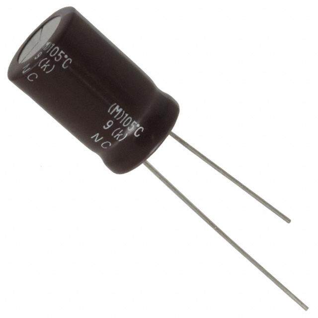
| 描述 | CAP ALUM 33UF 35V 20% SMD铝质电解电容器-SMD 35volts 33uF 125c 8X6.2 |
| ESR(等效串联电阻) | - |
| 产品分类 | |
| 品牌 | Nichicon |
| 产品手册 | |
| 产品图片 |
|
| rohs | 符合RoHS无铅 / 符合限制有害物质指令(RoHS)规范要求 |
| 产品系列 | 铝电解电容器,铝质电解电容器-SMD,Nichicon UUB1V330MCL1GSUB |
| 数据手册 | |
| 产品型号 | UUB1V330MCL1GS |
| 不同温度时的使用寿命 | 125°C 时为 1000 小时 |
| 产品 | Aluminum Electrolytic Capacitors |
| 产品种类 | 铝质电解电容器-SMD |
| 其它名称 | 493-6467-1 |
| 包装 | 剪切带 (CT) |
| 商标 | Nichicon |
| 外壳直径 | 8 mm |
| 外壳长度 | 6.2 mm |
| 大小/尺寸 | 0.315" 直径(8.00mm) |
| 安装类型 | 表面贴装 |
| 容差 | 20 % |
| 封装 | Reel |
| 封装/外壳 | 径向,Can - SMD |
| 工作温度 | -40°C ~ 125°C |
| 工厂包装数量 | 1000 |
| 应用 | 通用 |
| 引线间距 | - |
| 最大工作温度 | + 125 C |
| 最小工作温度 | - 40 C |
| 标准包装 | 1 |
| 漏泄电流 | 34.65 uA |
| 电压额定值DC | 35 V |
| 电容 | 33 uF |
| 端接类型 | SMD/SMT |
| 类型 | - |
| 系列 | UB |
| 纹波电流 | 44 mA |
| 表面贴装焊盘尺寸 | 0.327" 长 x 0.327" 宽(8.30mm x 8.30mm) |
| 阻抗 | - |
| 额定电压 | 35V |
| 高度-安装(最大值) | 0.256"(6.50mm) |




- 商务部:美国ITC正式对集成电路等产品启动337调查
- 曝三星4nm工艺存在良率问题 高通将骁龙8 Gen1或转产台积电
- 太阳诱电将投资9.5亿元在常州建新厂生产MLCC 预计2023年完工
- 英特尔发布欧洲新工厂建设计划 深化IDM 2.0 战略
- 台积电先进制程称霸业界 有大客户加持明年业绩稳了
- 达到5530亿美元!SIA预计今年全球半导体销售额将创下新高
- 英特尔拟将自动驾驶子公司Mobileye上市 估值或超500亿美元
- 三星加码芯片和SET,合并消费电子和移动部门,撤换高东真等 CEO
- 三星电子宣布重大人事变动 还合并消费电子和移动部门
- 海关总署:前11个月进口集成电路产品价值2.52万亿元 增长14.8%


PDF Datasheet 数据手册内容提取
ALUMINUM ELECTROLYTIC CAPACITORS UUB Chip Type, High Reliability Chip type, high temperature range, for +125°C use. (Through 50V only) Applicable to automatic mounting machine UWH ULT fed with carrier tape. Compliant to the RoHS directive (2011/65/EU). High High AEC-Q200 compliant. Please contact us for details. Temperature Voltage Reflow UCJ Added ESR specification UUB High UUX at –40°C Temperature Specifications Item Performance Characteristics Category Temperature Range –40 to +125°C Rated Voltage Range 10 to 400V Rated Capacitance Range 1 to 330µF Capacitance Tolerance ±20% at 120Hz, 20°C Rated voltage (V) 10 to 50 160 to 400 Leakage Current Leakage Current After 1 minute's application of rated voltage at 20°C, leakage current is not more than 0.03CV (µA). I = 0.04CV+100( µA) max.(1 minute's at 20°C) Measurement frequency : 120Hz at 20°C Tangent of loss angle (tan δ) Rated voltage (V) 10 16 25 35 50 160 200 250 400 tan δ (MAX.) 0.32 0.24 0.21 0.18 0.18 0.30 0.30 0.30 0.30 Measurement frequency : 120Hz Rated voltage (V) 10 16 25 35 50 160 200 250 400 Stability at Low Temperature Impedance ratio Z–40°C / Z+20°C 12 8 6 4 4 8 8 8 12 ZT / Z20 (MAX.) The specifications listed at right shall be met when the Capacitance change Within ±30% of the initial capacitance value Endurance capacitors are restored to 20°C after the rated voltage is tan δ 300% or less than the intial specified value applied for 2000 hours (1000 hours for φ8 × 6.2) at 125°C. Leakage current Less than or equal to the initial specified value After storing the capacitors under no load at 125°C for 1000 hours and then performing voltage treatment based on JIS C 5101-4 Shelf Life clause 4.1 at 20°C, they shall meet the specified values for the endurance characteristics listed above. The capacitors are kept on a hot plate for 30 seconds, Resistance to soldering which is maintained at 250°C. The capacitors shall meet Capacitance change Within ±10% of the initial capacitance value heat the characteristic requirements listed at right when they tan δ Less than or equal to the initial specified value are removed from the plate and restored to 20°C. Leakage current Less than or equal to the initial specified value Marking Black print on the case top. Chip Type Type numbering system (Example : 10V 100µF) (φ8 × 6.2) Positive 1 2 3 4 5 6 7 8 9 10 11 12 13 14 1LC2oa5tp ˚NaCoc i.Mtaanrckeing Voltage Plastic0 .p3lMatAfoXrm. C±0.2 0.5MAX. U U B 1 A 1 0 1 M C L 1 G S Trade mark A2E10010V D±0.5φ L±0.3 B±0.2 H A±0.2A±0.2E CRaaptaecdit acnacpea tcoiltearTnaacnpecei n( 1(g±0 2c00oµ%dFe)) 8φ D× ×C6 .oL2nfigCuCroadLteion Negative 8 × 10 NL Rated voltage (10V) 10 × 10 NL (φ8 × 10, φ10) Positive Series name Plastic platform L12o5t ˚NCo M.arking Capacitance 0.3MAX. C±0.2 MAX. Type Trade mark Voltage 0.5 (mm) A2E33010V D±0.5φ B±0.2 A±0.2A±0.2E CABEφD × L 8 3882× ....63333.2 8 2883×.... 193310 111034 00×.. 2..51330 L±0.5 H Negative L 6.2 10 10 Pressure relief vent H 0.5 to 0.80.8 to 1.10.8 to 1.1 Dimensions V 10 16 25 35 50 Cap.(µF) Code 1A 1C 1E 1V 1H 010 100 8 × 6.2 24 022 220 8 × 6.2 38 033 330 8 × 6.2 44 8 × 10 46 047 470 8 × 6.2 48 8 × 10 52 10 × 10 58 100 101 8 × 6.2 58 8 × 10 66 8 × 10 74 10 × 10 80 220 221 8 × 10 90 10 × 10 102 10 × 10 116 Case size Rated 330 331 10 × 10 112 φD × L (mm) ripple V 160 200 250 400 Cap.(µF) Code 2C 2D 2E 2G 1 010 8× 10 26 Frequency coefficient of rated ripple current 1.8 1R8 8× 10 27 Frequency 50 Hz 120 Hz 300 Hz 1 kHz 10 kHz or more 2.2 2R2 10× 10 36 Coefficient 0.70 1.00 1.17 1.36 1.50 3.3 3R3 8× 10 28 10× 10 38 4.7 4R7 8× 10 36 10× 10 59 Taping specifications are given in page 23. 6.8 6R8 8× 10 42 10× 10 59 Case size Rated Recommended land size, soldering by reflow are given in 10 100 10× 10 59 10× 10 59 φD × L (mm) ripple page 18, 19. Rated ripple current (mArms) at 125°C 120Hz Please refer to page 3 for the minimum order quantity. 147 CAT.8100H
Mouser Electronics Authorized Distributor Click to View Pricing, Inventory, Delivery & Lifecycle Information: N ichicon: UUB1V470MNL1GS UUB1V101MNL1GS UUB1A101MCL1GS UUB1A221MNL1GS UUB1A331MNL1GS UUB1C101MNL1GS UUB1C221MNL1GS UUB1E470MCL1GS UUB1E101MNL1GS UUB1E221MNL1GS UUB1V330MCL1GS UUB1H100MCL1GS UUB1H220MCL1GS UUB1H330MNL1GS UUA1V4R7MCL1GS UUB1E100MNL1GS UUB1H470MNL1GS UUB2C100MNL1GS UUB2C6R8MNL1GS UUB2D100MNL1GS UUB2D4R7MNL1GS UUB2D6R8MNL1GS UUB2E3R3MNL1GS UUB2E4R7MNL1GS UUB2G010MNL1GS UUB2G1R2MNL1GS UUB2G1R8MNL1GS UUB2G2R2MNL1GS
 Datasheet下载