- 型号: UFX6000-VE
- 制造商: Microchip
- 库位|库存: xxxx|xxxx
- 要求:
| 数量阶梯 | 香港交货 | 国内含税 |
| +xxxx | $xxxx | ¥xxxx |
查看当月历史价格
查看今年历史价格
UFX6000-VE产品简介:
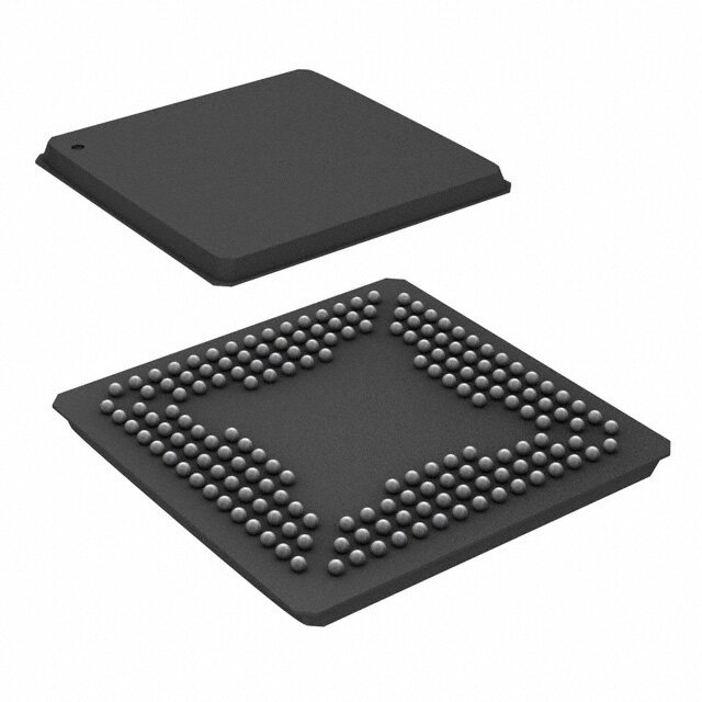
ICGOO电子元器件商城为您提供UFX6000-VE由Microchip设计生产,在icgoo商城现货销售,并且可以通过原厂、代理商等渠道进行代购。 UFX6000-VE价格参考¥133.54-¥157.75。MicrochipUFX6000-VE封装/规格:接口 - 专用, Graphics Controller Interface 225-LFBGA (13x13)。您可以下载UFX6000-VE参考资料、Datasheet数据手册功能说明书,资料中有UFX6000-VE 详细功能的应用电路图电压和使用方法及教程。
| 参数 | 数值 |
| 产品目录 | 集成电路 (IC)半导体 |
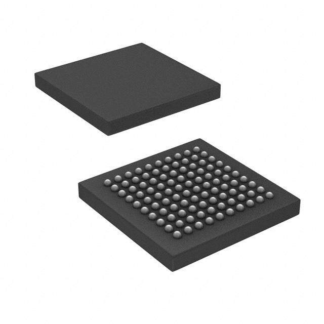
| 描述 | USB 2.0 GRAPHICS CTRLR 225LFBGAUSB 接口集成电路 USB 2.0 Hi-Speed Graphics Controller |
| 产品分类 | |
| 品牌 | Microchip Technology |
| 产品手册 | |
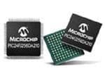
| 产品图片 | |
| rohs | 符合RoHS无铅 / 符合限制有害物质指令(RoHS)规范要求 |
| 产品系列 | 接口 IC,USB 接口集成电路,Microchip Technology UFX6000-VE* |
| 数据手册 | |
| 产品型号 | UFX6000-VE |
| 产品种类 | USB 接口集成电路 |
| 商标 | Microchip Technology |
| 安装风格 | SMD/SMT |
| 封装 | Tray |
| 封装/箱体 | LFBGA-225 |
| 工作电源电压 | 1.2 V, 1.8 V, 3.3 V |
| 工作电源电流 | 0.7 mA, 1.5 mA |
| 工厂包装数量 | 160 |
| 接口类型 | I2C, USB |
| 数据速率 | 480 Mbps |
| 最大工作温度 | + 70 C |
| 最小工作温度 | 0 C |
| 标准 | USB 2.0 |
| 标准包装 | 160 |
| 类型 | Controller |
| 系列 | UFX6000 |
| 速度 | High-Speed |




- 商务部:美国ITC正式对集成电路等产品启动337调查
- 曝三星4nm工艺存在良率问题 高通将骁龙8 Gen1或转产台积电
- 太阳诱电将投资9.5亿元在常州建新厂生产MLCC 预计2023年完工
- 英特尔发布欧洲新工厂建设计划 深化IDM 2.0 战略
- 台积电先进制程称霸业界 有大客户加持明年业绩稳了
- 达到5530亿美元!SIA预计今年全球半导体销售额将创下新高
- 英特尔拟将自动驾驶子公司Mobileye上市 估值或超500亿美元
- 三星加码芯片和SET,合并消费电子和移动部门,撤换高东真等 CEO
- 三星电子宣布重大人事变动 还合并消费电子和移动部门
- 海关总署:前11个月进口集成电路产品价值2.52万亿元 增长14.8%


PDF Datasheet 数据手册内容提取
UFX6000 USB 2.0 Hi-Speed Graphics Controller with VGA, HDMI/DVI, and Digital RGB Interfaces PRODUCT FEATURES Data Brief Highlights Graphics Subsystem — Integrated HDMI/DVI Controller and PHY Single-Chip Hi-Speed USB 2.0 Graphics Adapter – Complies with DVI specification v1.0 USB 2.0 Device Controller with Integrated USB 2.0 – Complies with HDMI specification v1.3 PHY – S/PDIF and I2S inputs for HDMI audio (2-channel uncompressed PCM) High Efficiency USB Graphics Adapter – Master I2C interface for DDC connection HDMI/DVI Display Connectivity via Integrated — Integrated Triple 10-bit Video DAC with VGA output HDMI/DVI Controller/PHY — Digital RGB Interface VGA Display Connectivity via Integrated Video DAC – 12/15-bit double data rate digital RGB – 24-bit single data rate digital RGB Support for External Display Interface IC’s via — Supports up to 2048x1152 (QWXGA) with 32-bit color Digital RGB Interface — 8-bit and 16-bit color support High Performance DDR2 SDRAM Controller with — Supports display cloning and extending Integrated DDR2 PHY — Standard and wide screen aspect ratios — Complies with VESA auto display identification Target Applications — Gamma correction — Color Look-Up Table (CLUT) USB to Video Adapters — Triple-buffered animations Docking Stations, USB Port Replicators — Graphics Engine Thin Clients – Optimized algorithms for static and dynamic content – I2C controller USB Monitors and Projectors DDR2 SDRAM Controller Embedded Systems — 16-bit data bus, 13-bit address bus — JEDEC DDR2 compliant (JESD79-2E) Features — Integrated DDR2 SDRAM PHY USB 2.0 Device Controller Power — Fully compliant with Universal Serial Bus Specification — Reduced power operating modes Revision 2.0 — Supports bus-powered and self-powered operation — Operates in HS (480 Mbps) mode Miscellaneous Features — Supports Control, Bulk-Out, and Interrupt-In endpoints — Optional EEPROM controller — Supports vendor specific commands — IEEE 1149.1 (JTAG) boundary scan TAP controller — Integrated USB 2.0 PHY Software — Integrated USB termination pull-up/pull-down resistors — Microsoft Windows® XP/Vista/7 drivers — Short circuit protection of USB differential signals Packaging & Environmental — 225-ball LFBGA, lead-free RoHS compliant package — Commercial temperature range (0°C to +70°C) PRODUCT PREVIEW SMSC UFX6000 Revision 1.3 (09-27-12)
USB 2.0 Hi-Speed Graphics Controller with VGA, HDMI/DVI, and Digital RGB Interfaces Order Number: UFX6000-VE for 225-Ball LFBGA lead-free RoHS compliant package (0 to +70°C temp range) This product meets the halogen maximum concentration values per IEC61249-2-21 For RoHS compliance and environmental information, please visit www.smsc.com/rohs Copyright © 2012 SMSC or its subsidiaries. All rights reserved. Circuit diagrams and other information relating to SMSC products are included as a means of illustrating typical applications. Consequently, complete information sufficient for construction purposes is not necessarily given. Although the information has been checked and is believed to be accurate, no responsibility is assumed for inaccuracies. SMSC reserves the right to make changes to specifications and product descriptions at any time without notice. Contact your local SMSC sales office to obtain the latest specifications before placing your product order. The provision of this information does not convey to the purchaser of the described semiconductor devices any licenses under any patent rights or other intellectual property rights of SMSC or others. All sales are expressly conditional on your agreement to the terms and conditions of the most recently dated version of SMSC's standard Terms of Sale Agreement dated before the date of your order (the "Terms of Sale Agreement"). The product may contain design defects or errors known as anomalies which may cause the product's functions to deviate from published specifications. Anomaly sheets are available upon request. SMSC products are not designed, intended, authorized or warranted for use in any life support or other application where product failure could cause or contribute to personal injury or severe property damage. Any and all such uses without prior written approval of an Officer of SMSC and further testing and/or modification will be fully at the risk of the customer. Copies of this document or other SMSC literature, as well as the Terms of Sale Agreement, may be obtained by visiting SMSC’s website at http://www.smsc.com. SMSC is a registered trademark of Standard Microsystems Corporation (“SMSC”). Product names and company names are the trademarks of their respective holders. The Microchip name and logo, and the Microchip logo are registered trademarks of Microchip Technology Incorporated in the U.S.A. and other countries. SMSC DISCLAIMS AND EXCLUDES ANY AND ALL WARRANTIES, INCLUDING WITHOUT LIMITATION ANY AND ALL IMPLIED WARRANTIES OF MERCHANTABILITY, FITNESS FOR A PARTICULAR PURPOSE, TITLE, AND AGAINST INFRINGEMENT AND THE LIKE, AND ANY AND ALL WARRANTIES ARISING FROM ANY COURSE OF DEALING OR USAGE OF TRADE. IN NO EVENT SHALL SMSC BE LIABLE FOR ANY DIRECT, INCIDENTAL, INDIRECT, SPECIAL, PUNITIVE, OR CONSEQUENTIAL DAMAGES; OR FOR LOST DATA, PROFITS, SAVINGS OR REVENUES OF ANY KIND; REGARDLESS OF THE FORM OF ACTION, WHETHER BASED ON CONTRACT; TORT; NEGLIGENCE OF SMSC OR OTHERS; STRICT LIABILITY; BREACH OF WARRANTY; OR OTHERWISE; WHETHER OR NOT ANY REMEDY OF BUYER IS HELD TO HAVE FAILED OF ITS ESSENTIAL PURPOSE, AND WHETHER OR NOT SMSC HAS BEEN ADVISED OF THE POSSIBILITY OF SUCH DAMAGES. Revision 1.3 (09-27-12) 2 SMSC UFX6000 PRODUCT PREVIEW
USB 2.0 Hi-Speed Graphics Controller with VGA, HDMI/DVI, and Digital RGB Interfaces General Description The UFX6000 is a high performance USB 2.0 graphics adapter with multiple graphics interfaces. The UFX6000 is an ideal solution for extending a PC workspace to an additional monitor without the need for an additional internal graphics card. With applications ranging from docking stations, USB port replicators, USB monitors/projectors, and embedded systems, the UFX6000 is targeted as a high performance, low cost USB-to-graphics solution. The UFX6000 contains an integrated USB 2.0 Device Controller, USB 2.0 PHY, USB Bulk-Out Controller, Control Endpoint, Interrupt-In Endpoint, DDR2 SDRAM Controller/PHY, Graphics Engine, HDMI/DVI Controller/PHY, Video DAC, TAP Controller, EEPROM Controller, and I2C Controller. Figure 1 details an internal block diagram of the UFX6000. EEPROM DDR2 SDRAM DDR2 PHY EEPROM PLLs Controller DDR2 Controller (DCTL) JTAG TAP FIFO Ctl Controller (FCT) Graphics Display Digital RGB Engine Controller USB Bulk Ctl (GPH) (DISP) USB 2.0 (URX) Device X U Ctrl M (UDC 2.0) ECnodnptoroinl t SCSRs CHoDnMtrIo/DllVeIr SI2S/PDIF Video DAC USB 2.0 USB Interrupt I2C HDMI PHY HDMI/DVI PHY Endpoint Controller VGA UFX6000 I2C Figure 1 Internal Block Diagram USB DEVICE CONTROLLER The USB Device Controller is fully compliant with the USB 2.0 Specification, enabling the device to operate in Hi-Speed (480 Mbps) mode. An integrated USB 2.0 PHY is provided on the USB port. The controller implements three USB endpoints: Control, Bulk-Out, and Interrupt-In. The Bulk-Out endpoint allows for uncompressed or compressed graphics data reception from the USB port. The USB Bulk-Out Controller collects the graphics information and transfers it to the Graphics Engine. Implementation of vendor-specific commands allows for access to the device System Control and Status Registers (SCSRs). SMSC UFX6000 3 Revision 1.3 (09-27-12) PRODUCT PREVIEW
USB 2.0 Hi-Speed Graphics Controller with VGA, HDMI/DVI, and Digital RGB Interfaces USB GRAPHICS ADAPTER The USB Graphics Adapter consists of the following main blocks: the Graphics Engine, Display Controller, HDMI/DVI Controller/PHY, Video DAC, and the Digital RGB Interface. Together, these blocks support high definition resolutions of up to 2048x1152 (QWXGA) with 32-bit true color in both standard and wide screen aspect ratios. The HDMI/DVI interface is compliant with the HDMI v1.3 and DVI v1.0 specifications and supports 2-channel uncompressed PCM audio via a S/PDIF or I2S input. The Display Controller also supports 8-bit and 16-bit color, gamma correction, Color Look-Up Table (CLUT) and triple-buffered animation. The DDC2B/EDID VESA standard is supported, allowing the host OS and device drivers to query the monitor’s frequency, resolution, and other features for true plug-and-play and intelligent mode setting capabilities. Once the graphics data has been received via the USB Bulk-Out Controller, it is sent to the Graphics Engine. If the data is compressed, the Graphics Engine decompresses it via algorithms that have been optimized for speed and quality. The device’s decompression algorithms have been designed to work seamlessly with the compression algorithms utilized in the software device drivers. The graphics data is then transferred to the SDRAM via the DDR2 SDRAM Controller. The Display Controller generates all display and interface timing signals, retrieves the graphics data from the DDR2 SDRAM, and sends it to the HDMI/DVI Controller/PHY, Video DAC, or Digital RGB Interface. The Digital RGB Interface may be used to connect external display interface IC’s (e.g., DisplayPort, etc.) via the provided RGB data channel busses and control signals. The Digital RGB Interface supports two modes of operation: 24-bit single data rate mode and 12/15-bit double data rate mode. 24-bit mode is single edge triggered and utilizes the full 24-bit data bus width. The 12/15-bit mode is triggered on both clock edges and utilizes 12/15-bits of the data bus width. DDR2 SDRAM INTERFACE The UFX6000 provides a full JEDEC compliant (JESD79-2E) DDR2 SDRAM Controller and PHY for interfacing to external DDR2 SDRAM. The DDR2 SDRAM interface is comprised of JEDEC standard 1.8V I/O signals grouped into control signals, a 16-bit data bus, and a 13-bit address bus. The DDR2 SDRAM Controller transfers the graphics data in and out of external SDRAM through the DDR2 SDRAM PHY. External SDRAM is used as storage for the graphics and acts a a buffer between the Graphics Engine and Display Controller. PERIPHERALS The UFX6000 also contains an EEPROM Controller, I2C Controller, and TAP Controller. The EEPROM Controller allows connection to an external EEPROM for automatic loading of static configuration data upon power-on, pin reset, or software reset. The EEPROM can be configured to load USB descriptors and USB device configuration. The integrated IEEE 1149.1 compliant TAP controller provides boundary scan via JTAG. Revision 1.3 (09-27-12) 4 SMSC UFX6000 PRODUCT PREVIEW
USB 2.0 Hi-Speed Graphics Controller with VGA, HDMI/DVI, and Digital RGB Interfaces Package Outline Figure 2 225-Ball LFBGA Package Figure 3 225-Ball LFBGA Package Ball Detail SMSC UFX6000 5 Revision 1.3 (09-27-12) PRODUCT PREVIEW
USB 2.0 Hi-Speed Graphics Controller with VGA, HDMI/DVI, and Digital RGB Interfaces Table 1 225-LFBGA Package Parameters MIN NOMINAL MAX REMARKS A - 1.30 1.40 Overall Package Height A1 0.25 - 0.40 Standoff A2 0.65 0.96 - Package Body Thickness D/E 12.90 13.00 13.10 Overall Package Size b 0.40 0.45 0.50 Ball Diameter b1 0.35 0.40 0.45 Finished Solder Mask Opening b2 0.45 0.50 0.55 Finished Ball Pad Diameter e 0.80 BSC Ball Pitch ccc - - 0.20 Coplanarity Notes: 1. All dimensions are in millimeters. 2. Dimension “b” is measured at the maximum ball diameter, parallel to primary datum “C”. 3. Primary datum “C” (seating plane) is defined by the spherical crowns of the contact balls. 4. The ball A1 identifier may vary, but is always located within the zone indicated. 5. Dimension “A” does not include attached external features, such as heat sink or chip capacitors. 6. The package ball solderable surface is Solder-Mask-Defined (SMD) type. Figure4 225-LFGBA Recommended PCB Land Pattern Revision 1.3 (09-27-12) 6 SMSC UFX6000 PRODUCT PREVIEW
Mouser Electronics Authorized Distributor Click to View Pricing, Inventory, Delivery & Lifecycle Information: M icrochip: UFX6000-VE UFX6000-VE-TR
 Datasheet下载
