 Datasheet下载
- 型号: UEI30-050-Q12P-C
- 制造商: Murata
- 库位|库存: xxxx|xxxx
- 要求:
| 数量阶梯 | 香港交货 | 国内含税 |
| +xxxx | $xxxx | ¥xxxx |
查看当月历史价格
查看今年历史价格
UEI30-050-Q12P-C产品简介:
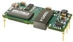
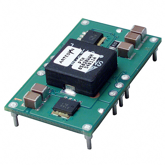
ICGOO电子元器件商城为您提供UEI30-050-Q12P-C由Murata设计生产,在icgoo商城现货销售,并且可以通过原厂、代理商等渠道进行代购。 UEI30-050-Q12P-C价格参考。MurataUEI30-050-Q12P-C封装/规格:直流转换器, 隔离模块 DC/DC 转换器 1 输出 5V 6A 9V - 36V 输入。您可以下载UEI30-050-Q12P-C参考资料、Datasheet数据手册功能说明书,资料中有UEI30-050-Q12P-C 详细功能的应用电路图电压和使用方法及教程。
| 参数 | 数值 |
| 产品目录 | |
| 描述 | CONVERT DC/DC 30W 5V SNGL POS隔离式DC/DC转换器 24Vin 5Vout 6A 30W Pos polarity |
| 产品分类 | DC DC ConvertersDC/DC转换器 |
| 品牌 | Murata Power Solutions |
| 产品手册 | |
| 产品图片 | |
| rohs | RoHS 合规性豁免无铅 / 符合限制有害物质指令(RoHS)规范要求 |
| 产品系列 | 隔离式DC/DC转换器,Murata Power Solutions UEI30-050-Q12P-CUEI30 |
| 数据手册 | |
| 产品型号 | UEI30-050-Q12P-C |
| 产品 | Isolated |
| 产品种类 | 隔离式DC/DC转换器 |
| 其它名称 | 811-3016 |
| 功率(W)-制造系列 | 30W |
| 功率(W)-最大值 | 30W |
| 包装 | 托盘 |
| 商标 | Murata Power Solutions |
| 大小/尺寸 | 1.92" 长 x 0.92" 宽 x 0.35" 高(48.8mm x 23.4mm x 8.9mm) |
| 安装类型 | 通孔 |
| 安装风格 | PCB |
| 封装 | Tray |
| 封装/外壳 | 6-DIP 模块 |
| 工作温度 | -40°C ~ 85°C |
| 工作温度范围 | - 40 C to + 85 C |
| 工厂包装数量 | 21 |
| 效率 | 89.5% |
| 标准包装 | 21 |
| 特性 | 远程开/关,OCP,OTP,SCP,UVLO |
| 电压-输入(最大值) | 36V |
| 电压-输入(最小值) | 9V |
| 电压-输出1 | 5V |
| 电压-输出2 | - |
| 电压-输出3 | - |
| 电压-隔离 | 2kV(2000V) |
| 电流-输出(最大值) | 6A |
| 类型 | 隔离模块 |
| 输入电压—公称值 | 24 V |
| 输入电压范围 | 9 V to 36 V |
| 输出功率 | 30 W |
| 输出数 | 1 |
| 输出电压—通道1 | 5 V |
| 输出电流—通道1 | 6 A |
| 输出端数量 | 1 |


- 商务部:美国ITC正式对集成电路等产品启动337调查
- 曝三星4nm工艺存在良率问题 高通将骁龙8 Gen1或转产台积电
- 太阳诱电将投资9.5亿元在常州建新厂生产MLCC 预计2023年完工
- 英特尔发布欧洲新工厂建设计划 深化IDM 2.0 战略
- 台积电先进制程称霸业界 有大客户加持明年业绩稳了
- 达到5530亿美元!SIA预计今年全球半导体销售额将创下新高
- 英特尔拟将自动驾驶子公司Mobileye上市 估值或超500亿美元
- 三星加码芯片和SET,合并消费电子和移动部门,撤换高东真等 CEO
- 三星电子宣布重大人事变动 还合并消费电子和移动部门
- 海关总署:前11个月进口集成电路产品价值2.52万亿元 增长14.8%
PDF Datasheet 数据手册内容提取
UEI30 Series www.murata-ps.com 30W Isolated Wide-Range DC-DC Converters Featuring a full 30 Watt output in 1.8 square inches of board area, the UEI series isolated DC/DC converter family offers efficient regulated DC power for printed circuit board mounting. TTyyppiiccaall uunniitt FEATURES PRODUCT OVERVIEW Small footprint DC/DC converter, ideal for high Wide range 4:1 inputs on the 0.92" x 1.92" x 0.35" programmable logic and FPGA’s. No minimum current applications converter are either 9 to 36 Volts DC (Q12 models) load is required. For systems requiring controlled 0.92" x 1.92" x 0.35" open frame package or 18 to 75 Volts DC (Q48 models), ideal for startup/shutdown, an external switch, transistor Wide range input voltages 9-36 and 18-75Vdc battery-powered and telecom equipment. Fixed or digital logic may be used to activate the remote output voltages from 3.3 VDC to 15 VDC are tightly On/Off control. Assembly and attachment for RoHS-6 hazardous regulated and may be trimmed within ±10% A wealth of self-protection features avoid both substance compliance of nominal output. Applications include small converter and external circuit problems. These Isolation up to 2250 VDC (basic), Q48 models instruments, computer-based systems, data com- include input undervoltage lockout and overtem- Up to 30W total output power with munications equipment, remote sensor systems, perature shutdown. The outputs current limit using overtemperature shutdown vehicle and portable electronics. the “hiccup” autorestart technique and the outputs High effi ciency synchronous rectifi er forward The UEI 30W Series includes full magnetic may be short-circuited indefi nitely. Additional topology and optical isolation up to 2250 Volts DC (basic features include output overvoltage and reverse Stable no-load operation with no required insulation), Q48 models. For connection to digital conduction elimination. external components systems, the outputs offer fast settling to current The synchronous rectifi er forward topology –40 to +85°C temperature range; see derating step loads and tolerance of higher capacitive offers high effi ciency for minimal heat buildup loads. Excellent ripple and noise specifi cations and “no fan” operation. Certifi ed to UL60950-1, CSA-C22.2 No. 234 assure compatibility to circuits using CPU’s, ASIC’s, safety approvals, and CE marking on 48V input only SIMPLIFIED SCHEMATIC Extensive self-protection shut down features RoHS-6 hazardous substance compliant +VOUT +VIN GATE DRIVE –VIN –VOUT ISOLATION BARRIER On/Off Control Control TRIM OPTO Reference, trim & ISOLATION Error Amplifier Typical topology is shown. For full details go to www.murata-ps.com/rohs (48V input only) www.murata-ps.com/support MDC_UEI Series 30W.B03 Page 1 of 18
UEI30 Series 30W Isolated Wide-Range DC-DC Converters PERFORMANCE SPECIFICATIONS SUMMARY AND ORDERING GUIDE Output Input Open Frame Power R/N (mVp-p) Regulation (Max.) Effi ciency Package, C80 VOUT IOUT NVoImN . Range noI IlNo,a d IIN, full (V) (A) (W) Typ. Max. Line Load (V) load (A) Min. Typ. Case Pinout Part Number (V) (mA) UEI30-033-Q12P-C 3.3 9 29.7 25 35 ±0.2% ±0.25% 24 9-36 130 1.39 87.3% 89% C80 P21 UEI30-033-Q48N-C 3.3 9 29.7 50 75 ±0.2% ±0.25% 48 18-75 50 0.69 87% 89.5% C80 P21 UEI30-050-Q12P-C 5 6 30 35 50 ±0.2% ±0.2% 24 9-36 130 1.4 88% 89.5% C80 P21 UEI30-050-Q48N-C 5 6 30 25 50 ±0.1% ±0.2% 48 18-75 130 0.7 87% 88.8% C80 P21 UEI30-120-Q12P-C 12 2.5 30 60 120 ±0.2% ±0.1% 24 9-36 75 1.4 87.5% 89% C80 P21 UEI30-120-Q48N-C 12 2.5 30 30 60 ±0.2% ±0.1% 48 18-75 40 0.7 87.5% 89% C80 P21 UEI30-150-Q12P-C 15 2 30 40 65 ±0.2% ±0.1% 24 9-36 95 1.4 87.5% 89% C80 P21 UEI30-150-Q48N-C 15 2 30 50 100 ±0.2% ±0.1% 48 18-75 50 0.7 87.5% 89.5% C80 P21 Please refer to the part number structure for additional options and complete ordering part numbers. Output capacitors are 1 μF ceramic in parallel with 10 μF electrolytic. Input cap is 22 μF, low ESR. All specifi cations are at nominal line voltage and full load, +25°C. unless otherwise noted. See These I/O caps are necessary for our test equipment and may not be needed for your application. detailed specifi cations. PART NUMBER STRUCTURE UEI30 - 050- Q48 N H Lx - C Nominal Output Voltage RoHS-6 hazardous substance compliance (does not claim EU RoHS exemption 7b–lead in solder) In tenths of a volt Input Voltage Range: Pin Length Option Q12 = 9-36V Blank = Std. pin length 0.25˝ (6.3mm) L1 = 0.110˝ (2.79mm)* Q48 = 18-75V L2 = 0.145˝ (3.68mm)* Conformal Coating Option *Special quantity order is required; Blank = No coating, standard no sample quantities available. H = Coating added, optional (built to order; contact Murata Power Solutions for MOQ and lead times.)* On/Off Control Logic: P = Positive N = Negative Note: Positive “P” logic is standard for Q12 models and optional special Some model number combinations order for Q48 models. Negative “N” logic is standard for Q48 models may not be available. Please contact and optional special order for Q12 models. Murata Power Solutions. Special Customer Configuration part numbers: 1)UEI30-033-Q12PH-31328 (3.3Vout @ 30W, Positive Logic, Conformal Coating, Hipot Tested to 2,000Vrms) 2)UEI30-050-Q12PH-31329 (5Vout @ 30W, Positive Logic, Conformal Coating, Hipot Tested to 2,000Vrms) 3)UEI30-050-Q12PL1-C-NI (5Vout @ 30W, Positive Logic, 0.110” Pin Length, Control loop changes for large capacitive load) www.murata-ps.com/support MDC_UEI Series 30W.B03 Page 2 of 18
UEI30 Series 30W Isolated Wide-Range DC-DC Converters FUNCTIONAL SPECIFICATIONS INPUT CHARACTERISTICS Start-up vUonldtaegr-e Re(bfl aecckte) d Input Current ended w Fuse Internal Reverse Remote On/Off Control Model Family threshold Sdohwutn- CRuirprepnlet 2 ITnsriraeunns-th OCSuihrtcopurutitt LLionwe StMaonddeby RecommFast-Blo IFTniylptpeuert PrPootleacrtitioy nCOunr/rOefnft Positive Logic Negative Logic V V mA pk-pk A2sec mA A mA A mA “P” model suffi x “N” model suffi x UEI30-033-Q12P-C 9.5 8.5 3.75 6 UEI30-033-Q48N-C 17.3 16.0* 1.89 6 1 1 UEI30-050-Q12P-C 9.5 8.0 3.75 6 OFF=Gnd pin or OFF=open pin 50 None, –0.7 to +1.2V or +10 to +15V UEI30-050-Q48N-C 17.0 16.2 1.88 6 install 30 0.05 L-C max. ON=open max. ON=Gnd UEI30-120-Q12P-C 9.5 8.3 3.75 3 6 external 3.5 pin or +10 to pin or –0.7 to fuse UEI30-120-Q48N-C 17.0 16.5 1.85 4 +15V max. +1.2V max. UEI30-150-Q12P-C 9.5 8.3 80 3.72 1 6 1 UEI30-150-Q48N-C 16.9 16.3 50 1.83 4 *Specifi ed at half load OUTPUT CHARACTERISTICS Model Family 5%A0c %ocVfuO LUVraToN caOyMd A%dRj uoasfn tVmgNeeOMn t %TCe mooefp fVefi OrcUaiTet un/ºrtCe CLaopwac rEietSsivRise t <μLiv0oFe.a0 ld2oiΩandg M Maxa,x . aHfitceOcrpv ufreaporu tvaelVotuc ltrttoieao-mgnseot avratl Minimum loading OV protection method Ripple/Noise(20 MHz bandwidth)8 Line/Load Regulation Effi ciency UEI30-033-Q12P-C 2 5.0 UEI30-033-Q48N-C 5.0 UEI30-050-Q12P-C 7.0 UEI30-050-Q48N-C 7.3 Magnetic ±10 ±0.02 2,000 No See ordering guide UEI30-120-Q12P-C 1 15.5 feedback UEI30-120-Q48N-C 14.1 UEI30-150-Q12P-C 18.5 UEI30-150-Q48N-C 24 Absolute Maximum Ratings ABSOLUTE MAXIMUM RATINGS Absolute maximums are stress ratings. Exposure of devices to Volts, max. continuous 0-36 VDC to rated specifi cations Q12 models greater than any of these conditions may adversely affect long-term Volts, transient, 100 mSec 50 VDC, no damage Input Voltage reliability. Proper operation under conditions other than those listed Volts, max. continuous 0-75 VDC to rated specifi cations Q48 models Volts, transient, 100 mSec 100 VDC, no damage in the Performance/Functional Specifi cations Table is not implied nor On/Off control, referred to –Vin -0.7 V. min to +15V max. recommended. Input Reverse Polarity Protection None, install external fuse Maximum Ratings Notes Output Overvoltage VOUT nom. +20% max. The transient specifi cations indicate that sample lots were success- Current-limited. Devices can fully tested for 100 mS at the transient stress voltage and were not withstand sustained short circuit Output Current without damage. The outputs are damaged. As a practical matter in your application, it is often diffi cult not intended to accept appreci- to determine how long an input overvoltage was applied. Therefore, able reverse current. do not exceed the continuous voltage rating. Device includes electronic over- Overtemperature Protection temperature shutdown protection under normal operation. Storage Temperature -55 to +125° C. Lead Temperature See soldering specifi cations www.murata-ps.com/support MDC_UEI Series 30W.B03 Page 3 of 18
UEI30 Series 30W Isolated Wide-Range DC-DC Converters ISOLATION CHARACTERISTICS DYNAMIC CHARACTERISTICS Start-up Time Input to Isolation Dynamic Load Model Family Output. Resistance CaIspoalcaittiaonnc e InsulaRtaiotinn gSafety Model Family (5R0e-s7p5o-n5s0e% VrIeNg tuol aVtOeUdT Remtoot eV OOUnT/Off FSrweqitucehnincgy Min Min load step) (Max.) regulated (Max.) VDC MΩ pF μsec mSec mSec KHz UEI30-033-Q12P-C 2000 1000 UEI30-033-Q12P-C 120 to 2% 275 UEI30-033-Q48N-C 2250 1000 UEI30-033-Q48N-C 180 to 2% 280 UEI30-050-Q12P-C 2000 1000 UEI30-050-Q12P-C 80 to 2% 275 UEI30-050-Q48N-C 2250 1000 UEI30-050-Q48N-C 100 to 1% 275 10 Basic 50 50 UEI30-120-Q12P-C 2000 1500 UEI30-120-Q12P-C 200 to 1% 275 UEI30-120-Q48N-C 2250 1500 UEI30-120-Q48N-C 150 to 1% 275 UEI30-150-Q12P-C 2000 1500 UEI30-150-Q12P-C 150 to 1% 275 UEI30-150-Q48N-C 2250 2000 UEI30-150-Q48N-C 150 to 1% 275 MISCELLANEOUS CHARACTERISTICS Output Current Output Output Relative Limit Inception Output Short Storage Thermal Short Short Output Humidity, Model Family 98% of VOUT, Circuit Circuit C(oiructupiut tD suhroarttieodn Pre-biased OperatinRga Tnegmeperature temrpaenrgaeture psrhoutetdcotiwonn/ non- after warmup Protection Current setup condensing to ground) Method A A ºC ºC ºC UEI30-033-Q12P-C 11.5 0.3 max. UEI30-033-Q48N-C 11.2 0.3 max. UEI30-050-Q12P-C 7.9 Current 3.0 limiting, Monotonic –40 to +85ºC; UEI30-050-Q48N-C 7.4 0.3 max. To +85ºC/ hiccup Continuous (external with Derating –55 to 125ºC 115 UEI30-120-Q12P-C 4.1 1.5 85% RH auto VOUT < VSET) (see Notes) UEI30-120-Q48N-C 3.65 restart 0.75 UEI30-150-Q12P-C 3.0 0.5 UEI30-150-Q48N-C 3.25 0.1 max. Specifi cation Notes: capacitance can retard transient response or possibly cause instability. Low ESR ceramic capacitors (1) All models are tested and specifi ed with external 1 μF and 10 μF parallel output capacitors and a may degrade dynamic performance. Be sure to thoroughly test your system under full load with all 22 μF external input capacitor. All capacitors are low ESR types. These capacitors are necessary to components installed. accommodate our test equipment and may not be required to achieve specifi ed performance in your (9) All models are fully operational and meet published specifi cations, including “cold start” at –40°C. applications. All models are stable and regulate within spec under no-load conditions. (10) Regulation specifi cations describe the deviation as the line input voltage or output load current is All specifi cations are typical unless noted. General conditions for Specifi cations are +25 deg.C, varied from a nominal midpoint value to either extreme. Vin=nominal, Vout=nominal, full load. Adequate airfl ow must be supplied for extended testing under (11) The output overvoltage protection is automatic recovery. The overvoltage may occur either from power. internal failure or from an external forcing voltage as in a shared power system. (2) Input Back Ripple Current is tested and specifi ed over a 5 Hz to 20 MHz bandwidth. Input fi ltering (12) Output overvoltage and short circuit protection is non-latching. When the overvoltage fault is is Cin=33 μF, 100V, Cbus=220 μF, 100V, Lbus=12 μH. removed, the converter will immediately recover. After an output overcurrent or short circuit, “hiccup” (3) Note that Maximum Power Derating curves indicate an average current at nominal input voltage. operation repeatedly attempts to restart the converter with a brief, full-current output. If the overcur- At higher temperatures and/or lower airfl ow, the DC/DC converter will tolerate brief full current rent condition still exists, the restart current will be removed and then tried again. This short current outputs if the total RMS current over time does not exceed the Derating curve. All Derating curves pulse prevents overheating and damaging the converter. Once the fault is removed, the converter are presented at sea level altitude. Be aware of reduced power dissipation with increasing density immediately resumes normal operation. altitude. (13) Do not exceed maximum power specifi cations when adjusting the output trim. (4) Refer to page 10 for MTBF values. (14) At zero output current, the output may contain low frequency components which exceed the (5) The On/Off Control is normally selected by a switch or an open collector or open drain transistor. ripple specifi cation. The output may be operated indefi nitely with no load. But it may also be driven with external logic or by applying appropriate external voltages which are (15) If reverse polarity is accidentally applied to the input, to ensure reverse input protection with full referenced to Input Common and do not exceed the On/Off voltage specifi cations. output load, always connect an external input fuse in series with the +Vin input. Use approximately (6) Output current limiting begins when the output voltage degrades approximately 2% from the twice the full input current rating with nominal input voltage. selected setting. CAUTION: This product is not internally fused. To comply with safety agency certifi cations and to (7) The outputs are not intended to sink appreciable reverse current. avoid injury to personnel or equipment, the user must connect an external fast-blow fuse to the input (8) Output noise may be further reduced by adding an external fi lter. Low voltage logic circuits may terminals. See fuse information. have a small voltage margin between logic ZERO and logic ONE, requiring noise suppression. Use only as much output fi ltering as needed to achieve your noise requirements. Excessive output www.murata-ps.com/support MDC_UEI Series 30W.B03 Page 4 of 18
UEI30 Series 30W Isolated Wide-Range DC-DC Converters PERFORMANCE DATA UEI30-033-Q12 Effi ciency vs. Line Voltage and Load Current @ 25°C Maximum Current Temperature Derating @Sea Level (VIN = 12V, airfl ow is from input to output) 90 9 8.8 Natural convection 85 8.6 0.5 m/s (100 LFM) 1.0 m/s (200 LFM) 8.4 1.5 m/s (300 LFM) %) 80 Vin = 36 V mps) 8.2 2.0 m/s (400 LFM) Efficiency ( 7705 VVViiinnn === 2914 2V VV Output Current (A 777...8468 65 7.2 7 20 25 30 35 40 45 50 55 60 65 70 75 80 85 90 60 Ambient Temperature (ºC) 0 1 2 3 4 5 6 7 8 9 Load Current (Amps) UEI30-033-Q48 Effi ciency vs. Line Voltage and Load Current @ 25°C Maximum Current Temperature Derating @Sea Level (VIN = 24V, airfl ow is from input to output) 100 9.1 90 9 80 mps) 8.9 N0.a5t umra/ls c(o1n0v0e LcFtiMon) Efficiency (%) 567000 VVVViiiinnnn ==== 47128584 VVVV Output Current (A 888...678 1.0 m/s (200 LFM) 40 8.5 20 25 30 35 40 45 50 55 60 65 70 75 80 85 90 30 Ambient Temperature (ºC) 20 0 1 2 3 4 5 6 7 8 9 Load Current (Amps) UEI30-033-Q48 Maximum Current Temperature Derating @Sea Level (VIN = 48V, airfl ow is from input to output) 9.1 9 mps) 8.9 N0.a5t umra/ls c(o1n0v0e LcFtiMon) Output Current (A 88..78 1.0 m/s (200 LFM) 8.6 8.5 20 25 30 35 40 45 50 55 60 65 70 75 80 85 90 Ambient Temperature (ºC) www.murata-ps.com/support MDC_UEI Series 30W.B03 Page 5 of 18
UEI30 Series 30W Isolated Wide-Range DC-DC Converters PERFORMANCE DATA UEI30-050-Q12 Effi ciency vs. Line Voltage and Load Current @ 25°C Maximum Current Temperature Derating @Sea Level (VIN = 12 or 24V, airfl ow is from input to output) 100 6.10 90 6.00 80 mps) 5.90 Natural convection Efficiency (%) 567000 VVVViiiinnnn ==== 23114602 VVVV Output Current (A 555...678000 40 5.50 20 25 30 35 40 45 50 55 60 65 70 75 80 85 90 30 Ambient Temperature (ºC) 20 0 1.00 2.00 3.00 4.00 5.00 6.00 Load Current (Amps) UEI30-050-Q48 Effi ciency vs. Line Voltage and Load Current @ 25°C Maximum Current Temperature Derating @Sea Level (VIN = 18V, transverse airfl ow) 100 90 6.1 80 6.0 Efficiency (%) 567000 VVVViiiinnnn ==== 47128584 VVVV Output Current (Amps) 555...789 N011...a505t ummmra///lsss c(((o123n000v000e LLLcFFFtiMMMon))) 40 5.6 30 5.5 20 25 30 35 40 45 50 55 60 65 70 75 80 85 90 Ambient Temperature (ºC) 20 0 1.00 2.00 3.00 4.00 5.00 6.00 Load Current (Amps) Maximum Current Temperature Derating @Sea Level UEI30-050-Q48 Maximum Current Temperature Derating @Sea Level (VIN = 24V, transverse airfl ow) (VIN = 48V, transverse airfl ow) 6.1 6.1 Output Current (Amps) 55556.....67890 Natural convection Output Current (Amps) 5556....7890 N0.a5t umra/ls c(o1n0v0e LcFtiMon) 5.6 5.5 20 25 30 35 40 45 50 55 60 65 70 75 80 85 90 5.5 20 25 30 35 40 45 50 55 60 65 70 75 80 85 90 Ambient Temperature (ºC) Ambient Temperature (ºC) www.murata-ps.com/support MDC_UEI Series 30W.B03 Page 6 of 18
UEI30 Series 30W Isolated Wide-Range DC-DC Converters PERFORMANCE DATA UEI30-120-Q12 Effi ciency vs. Line Voltage and Load Current @ 25°C Power Dissipation vs. Load Current @ 25°C 4.5 90 Vin = 36 V 88 4.0 Vin = 24 V Vin = 12 V 8846 Watts) 3.5 Vin = 9 V ficiency (%) 77886802 VVVViiiinnnn ==== 23 1 4692 VVVV Power Dissipation ( 223...050 Ef 74 1.5 72 1.0 70 0.5 0.7 0.9 1.1 1.3 1.5 1.7 1.9 2.1 2.3 2.5 68 Load Current (Amps) 0.5 0.7 0.9 1.1 1.3 1.5 1.7 1.9 2.1 2.3 2.5 Load Current (Amps) Maximum Current Temperature Derating @Sea Level UEI30-120-Q12 Maximum Current Temperature Derating @Sea Level (VIN = 9-24V, transverse airfl ow) (VIN = 36V, transverse airfl ow) 2.55 2.55 2.50 2.50 0.5 m/s (100 LFM) 100 LFM 1.0 m/s (200 LFM) 2.45 Output Current (Amps) 22..4405 Output Current (Amps)22..3450 2.30 2.35 2.25 2.20 2.30 20 25 30 35 40 45 50 55 60 65 70 75 80 85 20 25 30 35 40 45 50 55 60 65 70 75 80 85 Ambient Temperature (ºC) Ambient Temperature (ºC) www.murata-ps.com/support MDC_UEI Series 30W.B03 Page 7 of 18
UEI30 Series 30W Isolated Wide-Range DC-DC Converters PERFORMANCE DATA UEI30-120-Q48 Effi ciency vs. Line Voltage and Load Current @ 25°C Power Dissipation vs. Load Current @ 25°C Vin = 75V 90 4.5 Vin = 48V 88 Vin = 24V 4.0 8846 Watts) 3.5 Vin = 18V Efficiency (%) 77886802 VVVViiiinnnn ==== 47128584 VVVV Power Dissipation ( 223...050 74 1.5 72 1.0 70 0.5 0.7 0.9 1.1 1.3 1.5 1.7 1.9 2.1 2.3 2.5 68 Load Current (Amps) 0.5 0.7 0.9 1.1 1.3 1.5 1.7 1.9 2.1 2.3 2.5 Load Current (Amps) Maximum Current Temperature Derating @Sea Level UEI30-120-Q48 Maximum Current Temperature Derating @Sea Level (VIN = 18-48V, transverse airfl ow) (VIN = 75V, transverse airfl ow) 3.00 2.60 2.75 2.55 2.50 100 LFM 2.50 0.5 m/s (100 LFM) mps) 2.25 Amps) 2.45 1.0 m/s (200 LFM) Output Current (A 12..7050 Output Current ( 22..3450 2.30 1.50 2.25 1.25 2.20 1.00 20 25 30 35 40 45 50 55 60 65 70 75 80 85 20 25 30 35 40 45 50 55 60 65 70 75 80 85 Ambient Temperature (ºC) Ambient Temperature (ºC) www.murata-ps.com/support MDC_UEI Series 30W.B03 Page 8 of 18
UEI30 Series 30W Isolated Wide-Range DC-DC Converters PERFORMANCE DATA UEI30-150-Q12 Effi ciency vs. Line Voltage and Load Current @ 25°C Power Dissipation vs. Load Current @ 25°C 4.5 90 88 4.0 86 84 Watts) 3.5 Efficiency (%) 77886802 VVVViiiinnnn ==== 23 1 4692 VVVV Power Dissipation ( 223...050 VViinn == 2346 VV 74 1.5 Vin = 12 V 72 Vin = 9 V 70 1.0 0.4 0.5 0.7 0.9 1.0 1.2 1.4 1.5 1.7 1.8 2.0 68 0.4 0.5 0.7 0.9 1.0 1.2 1.4 1.5 1.7 1.8 2.0 Load Current (Amps) Load Current (Amps) Maximum Current Temperature Derating @Sea Level UEI30-150-Q12 Maximum Current Temperature Derating @Sea Level (VIN = 9-24V, transverse airfl ow) (VIN = 36V, transverse airfl ow) 2.05 2.05 2.00 2.00 100 LFM 0.5 m/s (100 LFM) Output Current (Amps) 11..9905 Output Current (Amps) 11..9905 11..05 mm//ss ((230000 LLFFMM)) 1.85 1.85 1.80 1.80 20 25 30 35 40 45 50 55 60 65 70 75 80 85 20 25 30 35 40 45 50 55 60 65 70 75 80 85 Ambient Temperature (ºC) Ambient Temperature (ºC) UEI30-150-Q12 Maximum Current Temperature Derating @Sea Level (Natural convection) 2.5 2 ps) m 1.5 A nt ( Vin = 12 V urre Vin = 24 V C put 1 ut O 0.5 0 30 35 40 45 50 55 60 65 70 75 80 85 Ambient Temperature (ºC) www.murata-ps.com/support MDC_UEI Series 30W.B03 Page 9 of 18
UEI30 Series 30W Isolated Wide-Range DC-DC Converters PERFORMANCE DATA UEI30-150-Q48 Effi ciency vs. Line Voltage and Load Current @ 25°C Power Dissipation vs. Load Current @ 25°C 92 5.0 90 4.5 88 86 Watts) 34..50 VViinn == 4785VV Efficiency (%) 78888024 VVViiinnn === 472854 VVV Power Dissipation ( 223...050 VViinn == 2148VV Vin = 18 V 1.5 76 74 1.00.7 0.8 1.0 1.1 1.2 1.3 1.5 1.6 1.7 1.9 2.0 72 Load Current (Amps) 0.7 0.8 1.0 1.1 1.2 1.3 1.5 1.6 1.7 1.9 2.0 Load Current (Amps) Maximum Current Temperature Derating @Sea Level UEI30-150-Q48 Maximum Current Temperature Derating @Sea Level (VIN = 18-48V, transverse airfl ow) (VIN = 75V, transverse airfl ow) 2.2 2.2 2.0 Natural Convection 2.0 0.5 m/s (100 LFM) 1.0 m/s (200 LFM) 1.5 m/s (300 LFM) mps) 1.8 Amps) 1.8 Output Current (A 11..46 Output Current ( 11..46 1.2 1.2 1.0 1.0 20 25 30 35 40 45 50 55 60 65 70 75 80 85 20 25 30 35 40 45 50 55 60 65 70 75 80 85 Ambient Temperature (ºC) Ambient Temperature (ºC) www.murata-ps.com/support MDC_UEI Series 30W.B03 Page 10 of 18
UEI30 Series 30W Isolated Wide-Range DC-DC Converters MECHANICAL SPECIFICATIONS TOP VIEW 1.92 (48.8) PIN #1 Dimensions are in inches (mm shown for ref. only). Third Angle Projection 0.92 (23.4) Tolerances (unless otherwise specified): .XX ± 0.02 (0.5) .XXX ± 0.010 (0.25) Angles ± 2˚ SIDE VIEW Components are shown for reference only. 0.35 (8.9) 0.25 (6.4) MOUNTING PLANE 0.040 0.002 PIN WITH 0.071 0.002 SHOULDER BOTTOM VIEW 6X AT PINS 1-6 #6 1.800 (45.72) #3 CL 0.900 REF END VIEW (22.86) #5 #2 0.400 (10.16) .0300 (7.62) CL 0.100 (2.54) .0400 0.300 (7.62) (10.16) CL #1 #4 UEI30 Open Frame 30W Package C80 PHYSICAL CHARACTERISTICS INPUT/OUTPUT CONNECTIONS Copper alloy with gold plate over nickel Pin Function P21 Pin Function P21 Pin material underplate 1 + Vin 4 + Vout Pin diameter 0.04" (1.016mm) 2 - Vin 5 - Vout 3 Remote On/Off* 6 Trim Pin Finish Gold plate Weight 0.53 oz (15g) * The Remote On/Off can be provided with either positive (P suffi x) or negative (N suffi x) logic. Electromagnetic interference EN55022/CISPR22 (requires external fi lter) Flammability Rating UL 94V-0 Designed to meet IEC/EN/UL/cUL 60950-1, Safety CSA-C22.2 No. 60950-1 www.murata-ps.com/support MDC_UEI Series 30W.B03 Page 11 of 18
UEI30 Series 30W Isolated Wide-Range DC-DC Converters SHIPPING TRAYS AND BOXES Anti-static foam Label Label For 1–42 pc quantity For 43–84 pc quantity SHIPPING TRAY UEI30 modules are supplied in a 21-piece (3-by-7) shipping tray. The tray is an anti-static closed-cell polyethylene foam. Dimensions are shown below. 9.920 (252) +0.000 0.910 (23.1) TYP -0.062 0.455 (11.6) TYP 0.735 (18.7) 9.920 (252) +0.000 -0.062 0.625 (15.9) TYP 2.400 (61) TYP Dimensions in inches (mm) 0.25 R TYP 1.300 (33.0) TYP 0.25 CHAMFER TYP (4-PL) 7.800 1.06 (198.1) (26.9) www.murata-ps.com/support MDC_UEI Series 30W.B03 Page 12 of 18
UEI30 Series 30W Isolated Wide-Range DC-DC Converters Sometimes only a small ceramic capacitor is suffi cient. Since it is diffi cult to TECHNICAL NOTES totally characterize all applications, some experimentation may be needed. Input Fusing Note that external input capacitors must accept high speed switching currents. Certain applications and/or safety agencies may require fuses at the inputs of power conversion components. Fuses should also be used when there is the Because of the switching nature of DC/DC converters, the input of these possibility of sustained input voltage reversal which is not current-limited. For converters must be driven from a source with both low AC impedance and greatest safety, we recommend a fast blow fuse installed in the ungrounded adequate DC input regulation. Performance will degrade with increasing input input supply line. inductance. Excessive input inductance may inhibit operation. The DC input regulation specifi es that the input voltage, once operating, must never degrade The installer must observe all relevant safety standards and regulations. For below the Shut-Down Threshold under all load conditions. Be sure to use safety agency approvals, install the converter in compliance with the end-user adequate trace sizes and mount components close to the converter. safety standard. I/O Filtering, Input Ripple Current and Output Noise Input Reverse-Polarity Protection All models in this converter series are tested and specifi ed for input refl ected If the input voltage polarity is reversed, an internal diode will become forward ripple current and output noise using designated external input/output compo- biased and likely draw excessive current from the power source. If this source nents, circuits and layout as shown in the fi gures below. External input capaci- is not current-limited or the circuit appropriately fused, it could cause perma- tors (CIN in the fi gure) serve primarily as energy storage elements, minimizing nent damage to the converter. line voltage variations caused by transient IR drops in the input conductors. Input Under-Voltage Shutdown and Start-Up Threshold Users should select input capacitors for bulk capacitance (at appropriate frequencies), low ESR and high RMS ripple current ratings. In the fi gure below, Under normal start-up conditions, converters will not begin to regulate properly until the rising input voltage exceeds and remains at the Start-Up Threshold the CBUS and LBUS components simulate a typical DC voltage bus. Your specifi c system confi guration may require additional considerations. Please note that the Voltage (see Specifi cations). Once operating, converters will not turn off until the input voltage drops below the Under-Voltage Shutdown Limit. Subsequent values of CIN, LBUS and CBUS will vary according to the specifi c converter model. restart will not occur until the input voltage rises again above the Start-Up Threshold. This built-in hysteresis prevents any unstable on/off operation at a TO single input voltage. OSCILLOSCOPE CURRENT PROBE 1 Users should be aware however of input sources near the Under-Voltage +VIN Shutdown whose voltage decays as input current is consumed (such as capaci- + LBUS tor inputs), the converter shuts off and then restarts as the external capacitor VIN +– CBUS CIN recharges. Such situations could oscillate. To prevent this, make sure the operat- – ing input voltage is well above the UV Shutdown voltage AT ALL TIMES. 2 −VIN Start-Up Delay CIN = 33μF, ESR < 700mΩ @ 100kHz Assuming that the output current is set at the rated maximum, the Vin to Vout Start- CBUS = 220μF, ESR < 100mΩ @ 100kHz Up Delay (see Specifi cations) is the time interval between the point when the rising LBUS = 12μH input voltage crosses the Start-Up Threshold and the fully loaded regulated output Figure 2. Measuring Input Ripple Current voltage enters and remains within its specifi ed regulation band. Actual measured times will vary with input source impedance, external input capacitance, input volt- age slew rate and fi nal value of the input voltage as it appears at the converter. These converters include a soft start circuit to moderate the duty cycle of the PWM controller at power up, thereby limiting the input inrush current. +VOUT The On/Off Remote Control interval from inception to VOUT regulated assumes that the converter already has its input voltage stabilized above the C1 C2 SCOPE RLOAD Start-Up Threshold before the On command. The interval is measured from the On command until the output enters and remains within its specifi ed accuracy −VOUT band. The specifi cation assumes that the output is fully loaded at maximum rated current. Input Source Impedance C1 = 1μF These converters will operate to specifi cations without external components, C2 = 10μF LOW ES LOAD 2-3 INCHES (51-76mm) FROM MODULE assuming that the source voltage has very low impedance and reason- able input voltage regulation. Since real-world voltage sources have fi nite Figure 3. Measuring Output Ripple and Noise (PARD) impedance, performance is improved by adding external fi lter components. www.murata-ps.com/support MDC_UEI Series 30W.B03 Page 13 of 18
UEI30 Series 30W Isolated Wide-Range DC-DC Converters In critical applications, output ripple and noise (also referred to as periodic an unplanned Over Temperature shut down. Also, these graphs are all collected and random deviations or PARD) may be reduced by adding fi lter elements near Sea Level altitude. Be sure to reduce the derating for higher altitude. such as multiple external capacitors. Be sure to calculate component tempera- Output Overvoltage Protection (OVP) ture rise from refl ected AC current dissipated inside capacitor ESR. This converter monitors its output voltage for an over-voltage condition using Floating Outputs an on-board electronic comparator. The signal is optically coupled to the pri- Since these are isolated DC/DC converters, their outputs are “fl oating” with mary side PWM controller. If the output exceeds OVP limits, the sensing circuit respect to their input. The essential feature of such isolation is ideal ZERO will power down the unit, and the output voltage will decrease. After a time-out CURRENT FLOW between input and output. Real-world converters however do period, the PWM will automatically attempt to restart, causing the output volt- exhibit tiny leakage currents between input and output (see Specifi cations). age to ramp up to its rated value. It is not necessary to power down and reset These leakages consist of both an AC stray capacitance coupling component the converter for the this automatic OVP-recovery restart. and a DC leakage resistance. When using the isolation feature, do not allow If the fault condition persists and the output voltage climbs to excessive the isolation voltage to exceed specifi cations. Otherwise the converter may levels, the OVP circuitry will initiate another shutdown cycle. This on/off cycling be damaged. Designers will normally use the negative output (-Output) as is referred to as “hiccup” mode. the ground return of the load circuit. You can however use the positive output (+Output) as the ground return to effectively reverse the output polarity. Output Fusing The converter is extensively protected against current, voltage and temperature Minimum Output Loading Requirements extremes. However, your application circuit may need additional protection. In the These converters employ a synchronous rectifi er design topology. All models extremely unlikely event of output circuit failure, excessive voltage could be applied regulate within specifi cation and are stable under no load to full load conditions. to your circuit. Consider using an appropriate external protection. Operation under no load might however slightly increase output ripple and noise. Output Current Limiting Thermal Shutdown As soon as the output current increases to approximately its overcurrent limit, To protect against thermal over-stress, these converters include thermal shut- the DC/DC converter will enter a current-limiting mode. The output voltage will down circuitry. If environmental conditions cause the temperature of the DC/ decrease proportionally with increases in output current, thereby maintaining a DC’s to rise above the Operating Temperature Range up to the shutdown tem- somewhat constant power output. This is commonly referred to as power limiting. perature, an on-board electronic temperature sensor will power down the unit. When the temperature decreases below the turn-on threshold, the converter Current limiting inception is defi ned as the point at which full power falls will automatically restart. There is a small amount of hysteresis to prevent below the rated tolerance. See the Performance/Functional Specifi cations. Note rapid on/off cycling. CAUTION: If you operate too close to the thermal limits, the particularly that the output current may briefl y rise above its rated value. This converter may shut down suddenly without warning. Be sure to thoroughly test enhances reliability and continued operation of your application. If the output your application to avoid unplanned thermal shutdown. current is too high, the converter will enter the short circuit condition. Temperature Derating Curves Output Short Circuit Condition The graphs in this data sheet illustrate typical operation under a variety of condi- When a converter is in current-limit mode, the output voltage will drop as tions. The Derating curves show the maximum continuous ambient air temperature the output current demand increases. If the output voltage drops too low, the and decreasing maximum output current which is acceptable under increasing magnetically coupled voltage used to develop PWM bias voltage will also drop, forced airfl ow measured in Linear Feet per Minute (“LFM”). Note that these are thereby shutting down the PWM controller. Following a time-out period, the AVERAGE measurements. The converter will accept brief increases in temperature PWM will restart, causing the output voltage to begin rising to its appropriate and/or current or reduced airfl ow as long as the average is not exceeded. value. If the short-circuit condition persists, another shutdown cycle will initi- ate. This on/off cycling is called “hiccup mode.” The hiccup cycling reduces the Note that the temperatures are of the ambient airfl ow, not the converter average output current, thereby preventing excessive internal temperatures. itself which is obviously running at higher temperature than the outside air. Also note that “natural convection” is defi ned as very fl ow rates which are not Trimming the Output Voltage using fan-forced airfl ow. Depending on the application, “natural convection” is The Trim input to the converter allows the user to adjust the output voltage over usually about 30-65 LFM but is not equal to still air (0 LFM). the rated trim range (please refer to the Specifi cations). In the trim equations and circuit diagrams that follow, trim adjustments use either a trimpot or a single Murata Power Solutions makes Characterization measurements in a closed fi xed resistor connected between the Trim input and either the +Vout or –Vout cycle wind tunnel with calibrated airfl ow. We use both thermocouples and an terminals. (On some converters, an external user-supplied precision DC voltage infrared camera system to observe thermal performance. As a practical matter, may also be used for trimming). Trimming resistors should have a low tempera- it is quite diffi cult to insert an anemometer to precisely measure airfl ow in ture coeffi cient (±100 ppm/deg.C or less) and be mounted close to the converter. most applications. Sometimes it is possible to estimate the effective airfl ow if Keep leads short. If the trim function is not used, leave the trim unconnected. you thoroughly understand the enclosure geometry, entry/exit orifi ce areas and With no trim, the converter will exhibit its specifi ed output voltage accuracy. the fan fl owrate specifi cations. There are two CAUTIONs to observe for the Trim input: CAUTION: If you exceed these Derating guidelines, the converter may have www.murata-ps.com/support MDC_UEI Series 30W.B03 Page 14 of 18
UEI30 Series 30W Isolated Wide-Range DC-DC Converters CAUTION: To avoid unplanned power down cycles, do not exceed EITHER the Remote On/Off Control maximum output voltage OR the maximum output power when setting the trim. On the input side, a remote On/Off Control can be specifi ed with either positive Be particularly careful with a trimpot. If the output voltage is excessive, the OVP or negative logic as follows: circuit may inadvertantly shut down the converter. If the maximum power is Positive: Models equipped with Positive Logic are enabled when the On/Off exceeded, the converter may enter current limiting. If the power is exceeded for an extended period, the converter may overheat and encounter overtempera- pin is left open or is pulled high to +VIN with respect to –VIN. An internal bias ture shut down. current causes the open pin to rise to +VIN. Some models will also turn on at lower intermediate voltages (see Specifi cations). Positive-logic devices are CAUTION: Be careful of external electrical noise. The Trim input is a senstive disabled when the On/Off is grounded or brought to within a low voltage (see input to the converter’s feedback control loop. Excessive electrical noise may Specifi cations) with respect to –VIN. cause instability or oscillation. Keep external connections short to the Trim Negative: Models with negative logic are on (enabled) when the On/Off is input. Use shielding if needed. grounded or brought to within a low voltage (see Specifi cations) with respect to –VIN. The device is off (disabled) when the On/Off is left open or is pulled high +VOUT to +15VDC Max. with respect to –VIN. −VIN Dynamic control of the On/Off function should be able to sink the speci- fi ed signal current when brought low and withstand appropriate voltage when brought high. Be aware too that there is a fi nite time in milliseconds ON/OFF 75-22 (see Specifi cations) between the time of On/Off Control activation and stable, TRIM TURNS LOAD CONTROL regulated output. This time will vary slightly with output load type and current and input conditions. +VIN −VOUT +VOUT +VIN Figure 4. Trim adjustments using a trimpot Trim Equations ON/OFF TRIM LOAD CONTROL R TRIMDOWN Trim Up Trim Down <Connect trim resistor <Connect trim resistor between Trim and –Vout> between Trim and +Vout> −VIN −VOUT UEI30-033-Q12/-Q48 12775 5110 (Vo - 2.5) Figure 5. Trim adjustments to decrease Output Voltage using a Fixed Resistor RT U P (Ω) = VO – 3.3 –2050 RT D O W N (Ω) = 3.3 – VO –2050 UEI30-050-Q12/-Q48 12775 5110 (Vo - 2.5) +VIN +VOUT RT U P (Ω) = VO – 5 –2050 RT D O W N (Ω) = 5 – VO –2050 UEI30-120-Q12/-Q48 25000 10000 (Vo-2.5) RT U P (Ω) = VO – 12 – 5110 RT D O W N (Ω) = 12 – VO –5110 COONN/TORFOFL TRIM RTRIMUP LOAD UEI30-150-Q12/-Q48 25000 10000 (Vo-2.5) RT U P (Ω) = VO – 15 – 5110 RT D O W N (Ω) = 15 – VO –5110 −VIN −VOUT Figure 6. Trim adjustments to increase Output Voltage using a Fixed Resistor Where Vo = Desired output voltage. Adjustment accuracy is subject to resis- tor tolerances and factory-adjusted output accuracy. Mount trim resistor close to converter. Use short leads. www.murata-ps.com/support MDC_UEI Series 30W.B03 Page 15 of 18
UEI30 Series 30W Isolated Wide-Range DC-DC Converters There are two CAUTIONs for the On/Off Control: Emissions Performance Murata Power Solutions measures its products for radio frequency emissions CAUTION: While it is possible to control the On/Off with external logic if you against the EN 55022 and CISPR 22 standards. Passive resistance loads are carefully observe the voltage levels, the preferred circuit is either an open employed and the output is set to the maximum voltage. If you set up your drain/open collector transistor or a relay (which can thereupon be controlled by own emissions testing, make sure the output load is rated at continuous power logic). The On/Off prefers to be set at approx. +15V (open pin) for the ON state, while doing the tests. assuming positive logic. The recommended external input and output capacitors (if required) are CAUTION: Do not apply voltages to the On/Off pin when there is no input included. Please refer to the fundamental switching frequency. All of this power voltage. Otherwise the converter may be permanently damaged. information is listed in the Product Specifi cations. An external discrete fi lter is installed and the circuit diagram is shown below. Resistive +VCC MODEL# UEI30-050-Q48N-C Load 30W 48 Vdc in, 5 Vout, 6 Amps UUT V+ 3 CC56 C1 C2 C3 C4 L1 C8 C7 Vin + Vout + RcinoemLsnsioitedsaatetiadin vlaee r ON/OFF CONTROL V- Vin - Vout - 1 -VIN Figure 8. Conducted Emissions Test Circuit [1]Conducted Emissions Parts List Figure 7. Driving the On/Off Control Pin (suggested circuit) Reference Description L1 500μH, 4.1A C8 Electrolytic Capacitor 100μfd, 100V C1, C2, C3 C4, C5, C6, C7 3.3μfd, 50V [2]Conducted Emissions Test Equipment Used Rohde & Schwarz EMI Test Receiver (9KHz – 1000MHz) ESPC Rohde & Schwarz Software ESPC-1 Ver. 2.20 OHMITE 25W – 1 Ohm resistor combinations DC Source Programmable DC Power Supply Model 62012P-100-50 [3]Conducted Emissions Test Results dBμV CONAV 80 70 60 50 40 30 20 10 0 -10 -20 0.15 1.0 10.0 30.0 MHz Graph 1. Conducted emissions performance with fi lter, Negative Line, CISPR 22, Class B, full load, for UEI30-033-Q48N-C www.murata-ps.com/support MDC_UEI Series 30W.B03 Page 16 of 18
UEI30 Series 30W Isolated Wide-Range DC-DC Converters dBμV CONAV dBμV CONAV 80 80 70 70 60 60 50 50 40 40 30 30 20 20 10 10 0 0 -10 -10 -20 -20 0.15 1.0 10.0 30.0 0.15 1.0 10.0 30.0 MHz MHz Graph 2. Conducted emissions performance with fi lter, Negative Line, CISPR 22, Graph 5. Conducted emissions performance with fi lter, Negative Line, CISPR 22, Class B, 5.43A @ 48Vin, for UEI30-050-Q48N-C Class B, full load, for UEI30-150-Q12N-C dBμV CONAV dBμV CONAV 80 90 70 80 60 70 50 60 40 50 30 40 20 30 10 20 0 10 -10 0 -20 -10 0.15 1.0 10.0 30.0 0.15 1.0 10.0 30.0 MHz MHz Graph 3. Conducted emissions performance with fi lter, Negative Line, CISPR 22, Graph 6. Conducted emissions performance with fi lter, Negative Line, CISPR 22, Class B, full load, for UEI30-120-Q12N-C Class B, full load, for UEI30-150-Q48N-C dBμV CONAV 80 70 [4]Layout Recommendations 60 Most applications can use the fi ltering which is already installed inside the 50 converter or with the addition of the recommended external capacitors. For 40 greater emissions suppression, consider additional fi lter components and/or 30 20 shielding. Emissions performance will depend on the user’s PC board layout, 10 the chassis shielding environment and choice of external components. 0 Since many factors affect both the amplitude and spectra of emissions, we -10 -20 recommend using an engineer who is experienced at emissions suppression. 0.15 1.0 10.0 30.0 MHz Graph 4. Conducted emissions performance with fi lter, Negative Line, CISPR 22, Class B, full load, for UEI30-120-Q48N-C www.murata-ps.com/support MDC_UEI Series 30W.B03 Page 17 of 18
UEI30 Series 30W Isolated Wide-Range DC-DC Converters Mean Time Before Failure (MTBF) Table These fi gures use a standard MTBF probability calculation as an indication of component parts stress and life derating. The calculaton is based on separate MTBF values for all internal parts in addition to stated environmental conditions. Two MTBF values are presented. The Telcordia method is widely used in industry, partic- ularly telecom. The United States MIL-HDBK method is for military and industrial applications. Please refer to a qualifi ed reliability engineer for more background. Model Number MTBF (Hours) Method [1,2] UEI30-033-Q12N-C 2,676,902 Telcordia UEI30-033-Q12N-C 2,123,124 MIL-HDBK UEI30-033-Q12P-C 2,733,781 Telcordia UEI30-033-Q12P-C 2,142,206 MIL-HDBK UEI30-033-Q48N-C 3,416,592 Telcordia Notes: [1] Mean Time Before Failure is calculated using the Telcordia (Belcore) SR-332 Method UEI30-033-Q48N-C 3,172,548 MIL-HDBK 1, Case 3, ISSUE 2, ground fi xed controlled conditions, Tambient=+25°C, full output load, natural air convection. UEI30-033-Q48P-C 3,427,027 Telcordia [2] Mean Time Before Failure is calculated using MIL-HDBK-217FN2, GB ground benign, Tambient=+25°C, full output load, natural air convection. UEI30-033-Q48P-C 3,193,652 MIL-HDBK UEI30-050-Q12N-C 2,531,509 Telcordia UEI30-050-Q12N-C 2,207,508 MIL-HDBK UEI30-050-Q12P-C 2,554,127 Telcordia UEI30-050-Q12P-C 2,229,031 MIL-HDBK UEI30-120-Q48N-C 3,072,461 Telcordia UEI30-120-Q48N-C 2,510,927 MIL-HDBK UEI30-120-Q48P-C 2,900,319 Telcordia UEI30-120-Q48P-C 2,495,846 MIL-HDBK UEI30-150-Q48N-C 2,833,366 Telcordia UEI30-150-Q48N-C 2,408,836 MIL-HDBK UEI30-150-Q48P-C 2,776,615 Telcordia UEI30-150-Q48P-C 2,421,938 MIL-HDBK Soldering Guidelines Murata Power Solutions recommends the specifi cations below when installing these converters. These specifi cations vary depending on the solder type. Exceeding these specifi ca- tions may cause damage to the product. Your production environment may differ; therefore please thoroughly review these guidelines with your process engineers. Wave Solder Operations for through-hole mounted products (THMT) For Sn/Ag/Cu based solders: For Sn/Pb based solders: Maximum Preheat Temperature 115° C. Maximum Preheat Temperature 105° C. Maximum Pot Temperature 270° C. Maximum Pot Temperature 250° C. Maximum Solder Dwell Time 7 seconds Maximum Solder Dwell Time 6 seconds This product is subject to the following operating requirements Murata Power Solutions, Inc. and the Life and Safety Critical Application Sales Policy: 129 Flanders Road, Westborough, MA 01581 U.S.A. Refer to: http://www.murata-ps.com/requirements/ ISO 9001 and 14001 REGISTERED Murata Power Solutions, Inc. makes no representation that the use of its products in the circuits described herein, or the use of other technical information contained herein, will not infringe upon existing or future patent rights. The descriptions contained herein do not imply the granting of licenses to make, use, or sell equipment constructed in accordance therewith. Specifications are subject to change without notice. © 2018 Murata Power Solutions, Inc. www.murata-ps.com/support MDC_UEI Series 30W.B03 Page 18 of 18
Mouser Electronics Authorized Distributor Click to View Pricing, Inventory, Delivery & Lifecycle Information: M urata: UEI30-050-Q48P-C UEI30-050-Q48N-C UEI30-033-Q12N-C UEI30-033-Q48P-C UEI30-050-Q12N-C UEI30-120- Q12N-C UEI30-120-Q12P-C UEI30-120-Q48N-C UEI30-120-Q48P-C UEI30-150-Q12N-C UEI30-150-Q12P-C UEI30-150-Q48N-C UEI30-150-Q48P-C UEI30-033-Q48N-C UEI30-050-Q12P-C UEI30-033-Q12P-C