ICGOO在线商城 > 集成电路(IC) > PMIC - 稳压器 - 线性 > UA7815CKTTR
 Datasheet下载
- 型号: UA7815CKTTR
- 制造商: Texas Instruments
- 库位|库存: xxxx|xxxx
- 要求:
| 数量阶梯 | 香港交货 | 国内含税 |
| +xxxx | $xxxx | ¥xxxx |
查看当月历史价格
查看今年历史价格
UA7815CKTTR产品简介:
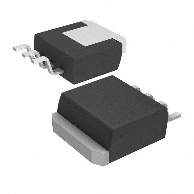
ICGOO电子元器件商城为您提供UA7815CKTTR由Texas Instruments设计生产,在icgoo商城现货销售,并且可以通过原厂、代理商等渠道进行代购。 UA7815CKTTR价格参考。Texas InstrumentsUA7815CKTTR封装/规格:PMIC - 稳压器 - 线性, Linear Voltage Regulator IC Positive Fixed 1 Output 15V 1.5A DDPAK/TO-263-3。您可以下载UA7815CKTTR参考资料、Datasheet数据手册功能说明书,资料中有UA7815CKTTR 详细功能的应用电路图电压和使用方法及教程。
| 参数 | 数值 |
| 产品目录 | 集成电路 (IC)半导体 |
| 描述 | IC REG LDO 15V 1.5A DDPAK线性稳压器 3P 1.5A Fixed 15V Pos Vltg Reg |
| 产品分类 | |
| 品牌 | Texas Instruments |
| 产品手册 | http://www.ti.com/lit/gpn/ua7815 |
| 产品图片 |
|
| rohs | 符合RoHS无铅 / 符合限制有害物质指令(RoHS)规范要求 |
| 产品系列 | 电源管理 IC,线性稳压器,Texas Instruments UA7815CKTTR- |
| 数据手册 | |
| 产品型号 | UA7815CKTTR |
| PCN封装 | |
| PCN设计/规格 | |
| 产品目录页面 | |
| 产品种类 | 线性稳压器 |
| 供应商器件封装 | DDPAK/TO-263-3 |
| 其它名称 | 296-21687-6 |
| 包装 | Digi-Reel® |
| 单位重量 | 1.443 g |
| 商标 | Texas Instruments |
| 安装类型 | 表面贴装 |
| 安装风格 | SMD/SMT |
| 封装 | Reel |
| 封装/外壳 | TO-263-4,D²Pak(3 引线+接片),TO-263AA |
| 封装/箱体 | TO-263-3 |
| 工作温度 | 0°C ~ 125°C |
| 工厂包装数量 | 500 |
| 最大工作温度 | + 125 C |
| 最大输入电压 | 30 V |
| 最小工作温度 | 0 C |
| 最小输入电压 | 17.5 V |
| 极性 | Positive |
| 标准包装 | 1 |
| 电压-跌落(典型值) | 2V @ 1A |
| 电压-输入 | 17.5 V ~ 30 V |
| 电压-输出 | 15V |
| 电流-输出 | 1.5A |
| 电流-限制(最小值) | - |
| 稳压器拓扑 | 正,固定式 |
| 稳压器数 | 1 |
| 系列 | UA7815 |
| 线路调整率 | 300 mV |
| 负载调节 | 300 mV |
| 输出电压 | 15 V |
| 输出电流 | 1.5 A |
| 输出端数量 | 1 |
| 输出类型 | Fixed |


PDF Datasheet 数据手册内容提取
Product Sample & Technical Tools & Support & Folder Buy Documents Software Community uA7805,uA7808,uA7810 uA7812,uA7815,uA7824 SLVS056P–MAY1976–REVISEDJANUARY2015 µA78xx Fixed Positive Voltage Regulators 1 Features 3 Description • 3-TerminalRegulators This series of fixed-voltage integrated-circuit voltage 1 regulators is designed for a wide range of • Availableinfixed5-V/8-V/10-V/12-V/15-V/24-V applications. These applications include on-card options regulation for elimination of noise and distribution • OutputCurrentupto1.5A problems associated with single-point regulation. • InternalThermal-OverloadProtection Each of these regulators can deliver up to 1.5 A of output current. The internal current-limiting and • HighPower-DissipationCapability thermal-shutdown features of these regulators • InternalShort-CircuitCurrentLimiting essentially make them immune to overload. In • OutputTransistorSafe-AreaCompensation addition to use as fixed-voltage regulators, these devices can be used with external components to • OutputCapacitorNotNeededforStability obtain adjustable output voltages and currents, and also can be used as the power-pass element in 2 Applications precisionregulators. • On-cardRegulation DeviceInformation(1) • PortableDevices PARTNUMBER PACKAGE BODYSIZE(NOM) • Computing& Servers TO-220(3) 10.16mmx8.82mm • Telecommunications μA78xx TO-220(3) 10.16mmx8.82mm TO-263(3) 10.06mmx9.02mm (1) For all available packages, see the orderable addendum at theendofthedatasheet. 4 Simplified Schematic +V µA78xx +VO 0.33µF 0.1µF 1 An IMPORTANT NOTICE at the end of this data sheet addresses availability, warranty, changes, use in safety-critical applications, intellectualpropertymattersandotherimportantdisclaimers.PRODUCTIONDATA.
uA7805,uA7808,uA7810 uA7812,uA7815,uA7824 SLVS056P–MAY1976–REVISEDJANUARY2015 www.ti.com Table of Contents 1 Features.................................................................. 1 8 DetailedDescription............................................ 11 2 Applications........................................................... 1 8.1 Overview.................................................................11 3 Description............................................................. 1 8.2 FunctionalSchematic..............................................11 4 SimplifiedSchematic............................................. 1 8.3 FeatureDescription.................................................11 8.4 DeviceFunctionalModes........................................11 5 RevisionHistory..................................................... 2 9 ApplicationandImplementation........................ 12 6 PinConfigurationandFunctions......................... 3 9.1 ApplicationInformation............................................12 7 Specifications......................................................... 4 9.2 TypicalApplication .................................................12 7.1 AbsoluteMaximumRatings......................................4 10 PowerSupplyRecommendations..................... 14 7.2 ESDRatings ............................................................4 11 Layout................................................................... 15 7.3 RecommendedOperatingConditions.......................4 7.4 ThermalInformation..................................................4 11.1 LayoutGuidelines.................................................15 7.5 ElectricalCharacteristics—uA7805.........................5 11.2 LayoutExample....................................................15 7.6 ElectricalCharacteristics—uA7808.........................6 12 DeviceandDocumentationSupport................. 15 7.7 ElectricalCharacteristics—uA7810.........................7 12.1 RelatedLinks........................................................15 7.8 ElectricalCharacteristics—uA7812........................8 12.2 Trademarks...........................................................15 7.9 ElectricalCharacteristics—uA7815.........................9 12.3 ElectrostaticDischargeCaution............................15 7.10 ElectricalCharacteristics—uA7824.....................10 12.4 Glossary................................................................15 7.11 TypicalCharacteristics..........................................10 13 Mechanical,Packaging,andOrderable Information........................................................... 15 5 Revision History ChangesfromRevisionO(August2012)toRevisionP Page • AddedApplications,DeviceInformationtable,PinFunctionstable,ESDRatingstable,ThermalInformationtable, TypicalCharacteristics,FeatureDescriptionsection,DeviceFunctionalModes,ApplicationandImplementation section,PowerSupplyRecommendationssection,Layoutsection,DeviceandDocumentationSupportsection,and Mechanical,Packaging,andOrderableInformationsection.................................................................................................. 1 • DeletedOrderingInformationtable........................................................................................................................................ 1 2 SubmitDocumentationFeedback Copyright©1976–2015,TexasInstrumentsIncorporated ProductFolderLinks:uA7805 uA7808 uA7810uA7812 uA7815 uA7824
uA7805,uA7808,uA7810 uA7812,uA7815,uA7824 www.ti.com SLVS056P–MAY1976–REVISEDJANUARY2015 6 Pin Configuration and Functions KC (TO-220) PACKAGE KCS OR KCT (TO-220) PACKAGE (TOPVIEW) (TOPVIEW) N N E O OUTPUT MMO B S O L E T COINOUPMTUPMTUOTN OMM CINOPMUMTON O O C C KTE (PowerFLEXTM) PACKAGE KTT (TO-263) PACKAGE (TOPVIEW) (TOPVIEW) N E OUTPUT N OUTPUT O E T O M O L COMMON M COMMON M S M B O O INPUT O INPUT C C PinFunctions PIN TYPE DESCRIPTION NAME NO. COMMON 2 — Ground INPUT 1 I SupplyInput OUTPUT 3 O VoltageOutput Copyright©1976–2015,TexasInstrumentsIncorporated SubmitDocumentationFeedback 3 ProductFolderLinks:uA7805 uA7808 uA7810uA7812 uA7815 uA7824
uA7805,uA7808,uA7810 uA7812,uA7815,uA7824 SLVS056P–MAY1976–REVISEDJANUARY2015 www.ti.com 7 Specifications 7.1 Absolute Maximum Ratings overvirtualjunctiontemperaturerange(unlessotherwisenoted) MIN MAX UNIT μA7824C 40 V Inputvoltage V l Allothers 35 T Operatingvirtualjunctiontemperature 150 °C J Leadtemperature 1,6mm(1/16in)fromcasefor10s 260 °C T Storagetemperaturerange –65 150 °C stg 7.2 ESD Ratings VALUE UNIT Humanbodymodel(HBM),perANSI/ESDA/JEDECJS-001,allpins(1) 3000 V(ESD) Electrostaticdischarge Chargeddevicemodel(CDM),perJEDECspecificationJESD22-C101, V allpins(2) 2000 (1) JEDECdocumentJEP155statesthat500-VHBMallowssafemanufacturingwithastandardESDcontrolprocess. (2) JEDECdocumentJEP157statesthat250-VCDMallowssafemanufacturingwithastandardESDcontrolprocess. 7.3 Recommended Operating Conditions MIN MAX UNIT μA7805 7 25 μA7808 10.5 25 μA7810 12.5 28 V Inputvoltage V l μA7812 14.5 30 μA7815 17.5 30 μA7824 27 38 I Outputcurrent 1.5 A O T Operatingvirtualjunctiontemperature 0 125 °C J 7.4 Thermal Information μA78XX THERMALMETRIC(1) KTE KCS,KCT, KTT UNIT KC 3PINS 3PINS 3PINS R Junction-to-ambientthermalresistance 23 19 25.3 θJA R Junction-to-case(top)thermalresistance 3 17 18 °C/W θJC(top) R Junction-to-exposed-padthermalresistance 2.7 3 1.94 θJP(top) (1) Formoreinformationabouttraditionalandnewthermalmetrics,seetheICPackageThermalMetricsapplicationreport(SPRA953). 4 SubmitDocumentationFeedback Copyright©1976–2015,TexasInstrumentsIncorporated ProductFolderLinks:uA7805 uA7808 uA7810uA7812 uA7815 uA7824
uA7805,uA7808,uA7810 uA7812,uA7815,uA7824 www.ti.com SLVS056P–MAY1976–REVISEDJANUARY2015 7.5 Electrical Characteristics — uA7805 atspecifiedvirtualjunctiontemperature,V =10V,I =500mA(unlessotherwisenoted) I O μA7805C PARAMETER TESTCONDITIONS T (1) UNIT J MIN TYP MAX I =5mAto1A,V =7Vto20V, 25°C 4.8 5 5.2 Outputvoltage O I V PD≤15W 0°Cto125°C 4.75 5.25 V =7Vto25V 3 100 I Inputvoltageregulation 25°C mV V =8Vto12V 1 50 I V =8Vto12V,f=120Hz 62 78 Ripplerejection(2) I 0°Cto125°C dB V =8Vto12V,f=120Hz(KCT) 68 I I =5mAto1.5A 15 100 O Outputvoltageregulation 25°C mV I =250mAto750mA 5 50 O Outputresistance f=1kHz 0°Cto125°C 0.017 Ω Temperaturecoefficientofoutputvoltage I =5mA 0°Cto125°C –1.1 mV/°C O Outputnoisevoltage f=10Hzto100kHz 25°C 40 μV Dropoutvoltage I =1A 25°C 2 V O Biascurrent 25°C 4.2 8 mA V =7Vto25V 1.3 I Biascurrentchange 0°Cto125°C mA I =5mAto1A 0.5 O Short-circuitoutputcurrent 25°C 750 mA Peakoutputcurrent 25°C 2.2 A (1) Pulse-testingtechniquesmaintainthejunctiontemperatureasclosetotheambienttemperatureaspossible.Thermaleffectsmustbe takenintoaccountseparately.Allcharacteristicsaremeasuredwitha0.33-μFcapacitoracrosstheinputanda0.1-μFcapacitoracross theoutput. (2) Thisparameterisvalidatedbydesignandverifiedduringproductcharacterization.Itisnottestedinproduction. Copyright©1976–2015,TexasInstrumentsIncorporated SubmitDocumentationFeedback 5 ProductFolderLinks:uA7805 uA7808 uA7810uA7812 uA7815 uA7824
uA7805,uA7808,uA7810 uA7812,uA7815,uA7824 SLVS056P–MAY1976–REVISEDJANUARY2015 www.ti.com 7.6 Electrical Characteristics — uA7808 atspecifiedvirtualjunctiontemperature,V =14V,I =500mA(unlessotherwisenoted) I O μA7808C PARAMETER TESTCONDITIONS T (1) UNIT J MIN TYP MAX I =5mAto1A,V =10.5Vto23V, 25°C 7.7 8 8.3 Outputvoltage O I V PD≤15W 0°Cto125°C 7.6 8.4 V =10.5Vto25V 6 160 I Inputvoltageregulation 25°C mV V =11Vto17V 2 80 I V =11.5Vto21.5V,f=120Hz 55 72 I Ripplerejection(2) V =11.5Vto21.5V,f=120Hz 0°Cto125°C dB I 62 (KCT) I =5mAto1.5A 12 160 O Outputvoltageregulation 25°C mV I =250mAto750mA 4 80 O Outputresistance f=1kHz 0°Cto125°C 0.016 Ω Temperaturecoefficientofoutputvoltage I =5mA 0°Cto125°C –0.8 mV/°C O Outputnoisevoltage f=10Hzto100kHz 25°C 52 μV Dropoutvoltage I =1A 25°C 2 V O Biascurrent 25°C 4.3 8 mA V =10.5Vto25V 1 I Biascurrentchange 0°Cto125°C mA I =5mAto1A 0.5 O Short-circuitoutputcurrent 25°C 450 mA Peakoutputcurrent 25°C 2.2 A (1) Pulse-testingtechniquesmaintainthejunctiontemperatureasclosetotheambienttemperatureaspossible.Thermaleffectsmustbe takenintoaccountseparately.Allcharacteristicsaremeasuredwitha0.33-μFcapacitoracrosstheinputanda0.1-μFcapacitoracross theoutput. (2) Thisparameterisvalidatedbydesignandverifiedduringproductcharacterization.Itisnottestedinproduction. 6 SubmitDocumentationFeedback Copyright©1976–2015,TexasInstrumentsIncorporated ProductFolderLinks:uA7805 uA7808 uA7810uA7812 uA7815 uA7824
uA7805,uA7808,uA7810 uA7812,uA7815,uA7824 www.ti.com SLVS056P–MAY1976–REVISEDJANUARY2015 7.7 Electrical Characteristics — uA7810 atspecifiedvirtualjunctiontemperature,V =17V,I =500mA(unlessotherwisenoted) I O μA7810C PARAMETER TESTCONDITIONS T (1) UNIT J MIN TYP MAX I =5mAto1A,V =12.5Vto25V, 25°C 9.6 10 10.4 Outputvoltage O I V PD≤15W 0°Cto125°C 9.5 10.5 V =12.5Vto28V 7 200 I Inputvoltageregulation 25°C mV V =14Vto20V 2 100 I Ripplerejection(2) V =13Vto23V,f=120Hz 0°Cto125°C 55 71 dB I I =5mAto1.5A 12 200 O Outputvoltageregulation 25°C mV I =250mAto750mA 4 100 O Outputresistance f=1kHz 0°Cto125°C 0.018 Ω Temperaturecoefficientofoutputvoltage I =5mA 0°Cto125°C –1 mV/°C O Outputnoisevoltage f=10Hzto100kHz 25°C 70 μV Dropoutvoltage I =1A 25°C 2 V O Biascurrent 25°C 4.3 8 mA V =12.5Vto28V 1 I Biascurrentchange 0°Cto125°C mA I =5mAto1A 0.5 O Short-circuitoutputcurrent 25°C 400 mA Peakoutputcurrent 25°C 2.2 A (1) Pulse-testingtechniquesmaintainthejunctiontemperatureasclosetotheambienttemperatureaspossible.Thermaleffectsmustbe takenintoaccountseparately.Allcharacteristicsaremeasuredwitha0.33-μFcapacitoracrosstheinputanda0.1-μFcapacitoracross theoutput. (2) Thisparameterisvalidatedbydesignandverifiedduringproductcharacterization.Itisnottestedinproduction. Copyright©1976–2015,TexasInstrumentsIncorporated SubmitDocumentationFeedback 7 ProductFolderLinks:uA7805 uA7808 uA7810uA7812 uA7815 uA7824
uA7805,uA7808,uA7810 uA7812,uA7815,uA7824 SLVS056P–MAY1976–REVISEDJANUARY2015 www.ti.com 7.8 Electrical Characteristics — uA7812 atspecifiedvirtualjunctiontemperature,V =19V,I =500mA(unlessotherwisenoted) I O μA7812C PARAMETER TESTCONDITIONS T (1) UNIT J MIN TYP MAX I =5mAto1A,V =14.5Vto27V, 25°C 11.5 12 12.5 Outputvoltage O I V PD≤15W 0°Cto125°C 11.4 12.6 V =14.5Vto30V 10 240 I Inputvoltageregulation 25°C mV V =16Vto22V 3 120 I V =15Vto25V,f=120Hz 55 71 Ripplerejection(2) I 0°Cto125°C dB V =15Vto25V,f=120Hz(KCT) 61 I I =5mAto1.5A 12 240 O Outputvoltageregulation 25°C mV I =250mAto750mA 4 120 O Outputresistance f=1kHz 0°Cto125°C 0.018 Ω Temperaturecoefficientofoutputvoltage I =5mA 0°Cto125°C –1 mV/°C O Outputnoisevoltage f=10Hzto100kHz 25°C 75 μV Dropoutvoltage I =1A 25°C 2 V O Biascurrent 25°C 4.3 8 mA V =14.5Vto30V 1 I Biascurrentchange 0°Cto125°C mA I =5mAto1A 0.5 O Short-circuitoutputcurrent 25°C 350 mA Peakoutputcurrent 25°C 2.2 A (1) Pulse-testingtechniquesmaintainthejunctiontemperatureasclosetotheambienttemperatureaspossible.Thermaleffectsmustbe takenintoaccountseparately.Allcharacteristicsaremeasuredwitha0.33-μFcapacitoracrosstheinputanda0.1-μFcapacitoracross theoutput. (2) Thisparameterisvalidatedbydesignandverifiedduringproductcharacterization.Itisnottestedinproduction. 8 SubmitDocumentationFeedback Copyright©1976–2015,TexasInstrumentsIncorporated ProductFolderLinks:uA7805 uA7808 uA7810uA7812 uA7815 uA7824
uA7805,uA7808,uA7810 uA7812,uA7815,uA7824 www.ti.com SLVS056P–MAY1976–REVISEDJANUARY2015 7.9 Electrical Characteristics — uA7815 atspecifiedvirtualjunctiontemperature,V =23V,I =500mA(unlessotherwisenoted) I O μA7815C PARAMETER TESTCONDITIONS T (1) UNIT J MIN TYP MAX I =5mAto1A,V =17.5Vto30V, 25°C 14.4 15 15.6 Outputvoltage O I V PD≤15W 0°Cto125°C 14.25 15.75 V =17.5Vto30V 11 300 I Inputvoltageregulation 25°C mV V =20Vto26V 3 150 I V =18.5Vto28.5V,f=120Hz 54 70 I Ripplerejection(2) V =18.5Vto28.5V,f=120Hz 0°Cto125°C dB I 60 (KCT) I =5mAto1.5A 12 300 O Outputvoltageregulation 25°C mV I =250mAto750mA 4 150 O Outputresistance f=1kHz 0°Cto125°C 0.019 Ω Temperaturecoefficientofoutputvoltage I =5mA 0°Cto125°C –1 mV/°C O Outputnoisevoltage f=10Hzto100kHz 25°C 90 μV Dropoutvoltage I =1A 25°C 2 V O Biascurrent 25°C 4.4 8 mA V =17.5Vto30V 1 I Biascurrentchange 0°Cto125°C mA I =5mAto1A 0.5 O Short-circuitoutputcurrent 25°C 230 mA Peakoutputcurrent 25°C 2.1 A (1) Pulse-testingtechniquesmaintainthejunctiontemperatureasclosetotheambienttemperatureaspossible.Thermaleffectsmustbe takenintoaccountseparately.Allcharacteristicsaremeasuredwitha0.33-μFcapacitoracrosstheinputanda0.1-μFcapacitoracross theoutput. (2) Thisparameterisvalidatedbydesignandverifiedduringproductcharacterization.Itisnottestedinproduction. Copyright©1976–2015,TexasInstrumentsIncorporated SubmitDocumentationFeedback 9 ProductFolderLinks:uA7805 uA7808 uA7810uA7812 uA7815 uA7824
uA7805,uA7808,uA7810 uA7812,uA7815,uA7824 SLVS056P–MAY1976–REVISEDJANUARY2015 www.ti.com 7.10 Electrical Characteristics — uA7824 atspecifiedvirtualjunctiontemperature,V =33V,I =500mA(unlessotherwisenoted) I O μA7824C PARAMETER TESTCONDITIONS T (1) UNIT J MIN TYP MAX I =5mAto1A,V =27Vto38V, 25°C 23 24 25 Outputvoltage O I V PD≤15W 0°Cto125°C 22.8 25.2 V =27Vto38V 18 480 I Inputvoltageregulation 25°C mV V =30Vto36V 6 240 I Ripplerejection(2) V =28Vto38V,f=120Hz 0°Cto125°C 50 66 dB I I =5mAto1.5A 12 480 O Outputvoltageregulation 25°C mV I =250mAto750mA 4 240 O Outputresistance f=1kHz 0°Cto125°C 0.028 Ω Temperaturecoefficientofoutputvoltage I =5mA 0°Cto125°C –1.5 mV/°C O Outputnoisevoltage f=10Hzto100kHz 25°C 170 μV Dropoutvoltage I =1A 25°C 2 V O Biascurrent 25°C 4.6 8 mA V =27Vto38V 1 I Biascurrentchange 0°Cto125°C mA I =5mAto1A 0.5 O Short-circuitoutputcurrent 25°C 150 mA Peakoutputcurrent 25°C 2.1 A (1) Pulse-testingtechniquesmaintainthejunctiontemperatureasclosetotheambienttemperatureaspossible.Thermaleffectsmustbe takenintoaccountseparately.Allcharacteristicsaremeasuredwitha0.33-μFcapacitoracrosstheinputanda0.1-μFcapacitoracross theoutput. (2) Thisparameterisvalidatedbydesignandverifiedduringproductcharacterization.Itisnottestedinproduction. 7.11 Typical Characteristics 4.5 4.0 A) m ( nt urre 3.5 C s a Bi 3.0 IBIAS 2.5 0 5 10 15 20 VIN-VOUT(typ) C001 Figure1. µA7805BiasCurrentvsVoltageDifferentialat25°C 10 SubmitDocumentationFeedback Copyright©1976–2015,TexasInstrumentsIncorporated ProductFolderLinks:uA7805 uA7808 uA7810uA7812 uA7815 uA7824
uA7805,uA7808,uA7810 uA7812,uA7815,uA7824 www.ti.com SLVS056P–MAY1976–REVISEDJANUARY2015 8 Detailed Description 8.1 Overview This series of fixed-voltage integrated-circuit voltage regulators is designed for a wide range of applications. These applications include on-card regulation for elimination of noise and distribution problems associated with single-point regulation. Each of these regulators can deliver up to 1.5 A of output current. The internal current- limiting and thermal-shutdown features of these regulators essentially make them immune to overload. In addition to use as fixed-voltage regulators, these devices can be used with external components to obtain adjustable output voltages and currents, and also can be used as the power-pass element in precision regulators. 8.2 Functional Schematic INPUT OUTPUT COMMON 8.3 Feature Description 8.3.1 ThermalOverload When the die temperature increases to unwanted levels, the device will reduce the output current to lower its temperature. Under heavy loads, the device may alternate between on and off output states to regulate temperature. 8.3.2 Short-CircuitCurrentLimiting In the event of a short circuit, the device will limit its own current to safe levels by lowering the bias voltage of internalpasstransistors.Ifthedevicebecomesoverheated,thethermaloverloadprotectionwilltakeover. 8.4 Device Functional Modes 8.4.1 Fixed-OutputMode Thesedevicesareavailableinfixed-outputvoltages.Seetheorderablepartlistforthedesiredoutput. Copyright©1976–2015,TexasInstrumentsIncorporated SubmitDocumentationFeedback 11 ProductFolderLinks:uA7805 uA7808 uA7810uA7812 uA7815 uA7824
uA7805,uA7808,uA7810 uA7812,uA7815,uA7824 SLVS056P–MAY1976–REVISEDJANUARY2015 www.ti.com 9 Application and Implementation NOTE Information in the following applications sections is not part of the TI component specification, and TI does not warrant its accuracy or completeness. TI’s customers are responsible for determining suitability of components for their purposes. Customers should validateandtesttheirdesignimplementationtoconfirmsystemfunctionality. 9.1 Application Information ThefollowingsectionshowsapplicationdetailsoftheµA78xxasalinearregulator. 9.2 Typical Application +V µA78xx +VO 0.33µF 0.1µF Figure2. Fixed-OutputRegulator 9.2.1 DesignRequirements • Inputsupplycapacitorrecommendedforfilteringnoiseontheinput • Outputsupplydecouplingcapacitorforstabilizingtheoutput 9.2.2 DetailedDesignProcedure 9.2.2.1 OperationWithaLoadCommontoaVoltageofOppositePolarity In many cases, a regulator powers a load that is not connected to ground but, instead, is connected to a voltage source of opposite polarity (e.g., operational amplifiers, level-shifting circuits, etc.). In these cases, a clamp diode should be connected to the regulator output as shown in Figure 3. This protects the regulator from output polarity reversalsduringstartupandshort-circuitoperation. +VI µA78xx +VO 1N4001 or Equivalent −VO Figure3. OutputPolarity-Reversal-ProtectionCircuit 9.2.2.2 Reverse-BiasProtection Occasionally, the input voltage to the regulator can collapse faster than the output voltage. This can occur, for example, when the input supply is crowbarred during an output overvoltage condition. If the output voltage is greater than approximately 7 V, the emitter-base junction of the series-pass element (internal or external) could breakdownandbedamaged.Topreventthis,adiodeshuntcanbeusedasshowninFigure4. 12 SubmitDocumentationFeedback Copyright©1976–2015,TexasInstrumentsIncorporated ProductFolderLinks:uA7805 uA7808 uA7810uA7812 uA7815 uA7824
uA7805,uA7808,uA7810 uA7812,uA7815,uA7824 www.ti.com SLVS056P–MAY1976–REVISEDJANUARY2015 Typical Application (continued) VI µA78xx +VO Figure4. Reverse-Bias-ProtectionCircuit 9.2.3 ApplicationCurves 2.40 2.20 2.00 V) ( ss1.80 o L e g1.60 a olt V1.40 1.20 VoltageLoss 1.00 0.00 0.25 0.50 0.75 1.00 1.25 1.50 OutputCurrent(A) C001 Figure5. µA7805VoltageLossvsOutputCurrentat25°C 9.2.4 GeneralConfigurations IN OUT + µ G VI A78xx COM IL − −VO Figure6. PositiveRegulatorinNegativeConfiguration(V MustFloat) I Input µA78xx Output R1 IO 0.33µF 0.1µF R2 A: The following formula is used when Vxxis the nominal output voltage (output to common) of the fixed regulators æV ö V =V +ç XX +I ÷R2 O XX è R1 Qø Figure7. Adjustable-OutputRegulator Copyright©1976–2015,TexasInstrumentsIncorporated SubmitDocumentationFeedback 13 ProductFolderLinks:uA7805 uA7808 uA7810uA7812 uA7815 uA7824
uA7805,uA7808,uA7810 uA7812,uA7815,uA7824 SLVS056P–MAY1976–REVISEDJANUARY2015 www.ti.com Typical Application (continued) Input µA78xx R1 0.33µF VO(Reg) Output IO IO= (VO/R1) + IOBias Current Figure8. CurrentRegulator 1N4001 20-V Input µA7815C VO= 15 V 0.33µF 0.1µF 1N4001 2µF 1µF 0.1µF 1N4001 −20-V Input µA7915C VO=−15V 1N4001 Figure9. RegulatedDualSupply 10 Power Supply Recommendations See Recommended Operating Conditions for the recommended power supply voltages for each variation of the μA78xx device. Different orderable part numbers will be able to tolerate different levels of voltage. It is also recommended to have a decoupling capacitor on the output of the μA78xx device's power supply to limit noise onthedeviceinput. 14 SubmitDocumentationFeedback Copyright©1976–2015,TexasInstrumentsIncorporated ProductFolderLinks:uA7805 uA7808 uA7810uA7812 uA7815 uA7824
uA7805,uA7808,uA7810 uA7812,uA7815,uA7824 www.ti.com SLVS056P–MAY1976–REVISEDJANUARY2015 11 Layout 11.1 Layout Guidelines Keep trace widths large enough to eliminate problematic I×R voltage drops at the input and output terminals. InputdecouplingcapacitorsshouldbeplacedasclosetotheμA78XXaspossible. 11.2 Layout Example COMMON (cid:19)(cid:17)(cid:22)(cid:22)(cid:3)PF INPUT COMMON OUTPUT (cid:19)(cid:17)(cid:20)(cid:3)PF Ground Ground Figure10. LayoutDiagram 12 Device and Documentation Support 12.1 Related Links The table below lists quick access links. Categories include technical documents, support and community resources,toolsandsoftware,andquickaccesstosampleorbuy. Table1.RelatedLinks TECHNICAL TOOLS& SUPPORT& PARTS PRODUCTFOLDER SAMPLE&BUY DOCUMENTS SOFTWARE COMMUNITY μA7805 Clickhere Clickhere Clickhere Clickhere Clickhere uA7808 Clickhere Clickhere Clickhere Clickhere Clickhere uA7810 Clickhere Clickhere Clickhere Clickhere Clickhere uA7812 Clickhere Clickhere Clickhere Clickhere Clickhere uA7815 Clickhere Clickhere Clickhere Clickhere Clickhere uA7924 Clickhere Clickhere Clickhere Clickhere Clickhere 12.2 Trademarks 12.3 Electrostatic Discharge Caution Thesedeviceshavelimitedbuilt-inESDprotection.Theleadsshouldbeshortedtogetherorthedeviceplacedinconductivefoam duringstorageorhandlingtopreventelectrostaticdamagetotheMOSgates. 12.4 Glossary SLYZ022—TIGlossary. Thisglossarylistsandexplainsterms,acronyms,anddefinitions. 13 Mechanical, Packaging, and Orderable Information The following pages include mechanical, packaging, and orderable information. This information is the most current data available for the designated devices. This data is subject to change without notice and revision of thisdocument.Forbrowser-basedversionsofthisdatasheet,refertotheleft-handnavigation. Copyright©1976–2015,TexasInstrumentsIncorporated SubmitDocumentationFeedback 15 ProductFolderLinks:uA7805 uA7808 uA7810uA7812 uA7815 uA7824
PACKAGE OPTION ADDENDUM www.ti.com 12-Jan-2015 PACKAGING INFORMATION Orderable Device Status Package Type Package Pins Package Eco Plan Lead/Ball Finish MSL Peak Temp Op Temp (°C) Device Marking Samples (1) Drawing Qty (2) (6) (3) (4/5) UA7805CKC OBSOLETE TO-220 KC 3 TBD Call TI Call TI 0 to 125 UA7805C UA7805CKCE3 OBSOLETE TO-220 KC 3 TBD Call TI Call TI 0 to 125 UA7805C UA7805CKCS ACTIVE TO-220 KCS 3 50 Pb-Free CU SN N / A for Pkg Type 0 to 125 UA7805C (RoHS) UA7805CKCSE3 ACTIVE TO-220 KCS 3 50 Pb-Free CU SN N / A for Pkg Type 0 to 125 UA7805C (RoHS) UA7805CKCT ACTIVE TO-220 KCT 3 50 Pb-Free CU SN N / A for Pkg Type 0 to 125 UA7805C (RoHS) UA7805CKTER OBSOLETE PFM KTE 3 TBD Call TI Call TI 0 to 125 UA7805C UA7805CKTTR ACTIVE DDPAK/ KTT 3 500 Green (RoHS CU SN Level-3-245C-168 HR 0 to 125 UA7805C TO-263 & no Sb/Br) UA7805CKTTRG3 ACTIVE DDPAK/ KTT 3 500 Green (RoHS CU SN Level-3-245C-168 HR 0 to 125 UA7805C TO-263 & no Sb/Br) UA7805QKC OBSOLETE TO-220 KC 3 TBD Call TI Call TI -40 to 125 UA7805QKTE OBSOLETE PFM KTE 3 TBD Call TI Call TI -40 to 125 UA7808CKC OBSOLETE TO-220 KC 3 TBD Call TI Call TI 0 to 125 UA7808C UA7808CKCE3 OBSOLETE TO-220 KC 3 TBD Call TI Call TI 0 to 125 UA7808C UA7808CKCS ACTIVE TO-220 KCS 3 50 Pb-Free CU SN N / A for Pkg Type 0 to 125 UA7808C (RoHS) UA7808CKCSE3 ACTIVE TO-220 KCS 3 50 Pb-Free CU SN N / A for Pkg Type 0 to 125 UA7808C (RoHS) UA7808CKCT ACTIVE TO-220 KCT 3 50 Pb-Free CU SN N / A for Pkg Type 0 to 125 UA7808C (RoHS) UA7808CKTER OBSOLETE PFM KTE 3 TBD Call TI Call TI 0 to 125 UA7808C UA7808CKTTR ACTIVE DDPAK/ KTT 3 500 Green (RoHS CU SN Level-3-245C-168 HR 0 to 125 UA7808C TO-263 & no Sb/Br) UA7808CKTTRG3 ACTIVE DDPAK/ KTT 3 500 Green (RoHS CU SN Level-3-245C-168 HR 0 to 125 UA7808C TO-263 & no Sb/Br) UA7808QKTE OBSOLETE PFM KTE 3 TBD Call TI Call TI -40 to 125 UA7810-W ACTIVE WAFERSALE YS 0 3952 TBD Call TI Call TI UA7810CKC OBSOLETE TO-220 KC 3 TBD Call TI Call TI 0 to 125 UA7810C UA7810CKCE3 OBSOLETE TO-220 KC 3 TBD Call TI Call TI 0 to 125 UA7810C Addendum-Page 1
PACKAGE OPTION ADDENDUM www.ti.com 12-Jan-2015 Orderable Device Status Package Type Package Pins Package Eco Plan Lead/Ball Finish MSL Peak Temp Op Temp (°C) Device Marking Samples (1) Drawing Qty (2) (6) (3) (4/5) UA7810CKCS ACTIVE TO-220 KCS 3 50 Pb-Free CU SN N / A for Pkg Type 0 to 125 UA7810C (RoHS) UA7810CKCSE3 ACTIVE TO-220 KCS 3 50 Pb-Free CU SN N / A for Pkg Type 0 to 125 UA7810C (RoHS) UA7810CKTER OBSOLETE PFM KTE 3 TBD Call TI Call TI 0 to 125 UA7810C UA7810CKTTR ACTIVE DDPAK/ KTT 3 500 Green (RoHS CU SN Level-3-245C-168 HR 0 to 125 UA7810C TO-263 & no Sb/Br) UA7810CKTTRG3 ACTIVE DDPAK/ KTT 3 500 Green (RoHS CU SN Level-3-245C-168 HR 0 to 125 UA7810C TO-263 & no Sb/Br) UA7810QKTE OBSOLETE PFM KTE 3 TBD Call TI Call TI -40 to 125 UA7812CKC OBSOLETE TO-220 KC 3 TBD Call TI Call TI 0 to 125 UA7812C UA7812CKCE3 OBSOLETE TO-220 KC 3 TBD Call TI Call TI UA7812C UA7812CKCS ACTIVE TO-220 KCS 3 50 Pb-Free CU SN N / A for Pkg Type 0 to 125 UA7812C (RoHS) UA7812CKCSE3 ACTIVE TO-220 KCS 3 50 Pb-Free CU SN N / A for Pkg Type 0 to 125 UA7812C (RoHS) UA7812CKCT ACTIVE TO-220 KCT 3 50 Pb-Free CU SN N / A for Pkg Type 0 to 125 UA7812C (RoHS) UA7812CKTER OBSOLETE PFM KTE 3 TBD Call TI Call TI 0 to 125 UA7812C UA7812CKTTR ACTIVE DDPAK/ KTT 3 500 Green (RoHS CU SN Level-3-245C-168 HR 0 to 125 UA7812C TO-263 & no Sb/Br) UA7812CKTTRG3 ACTIVE DDPAK/ KTT 3 500 Green (RoHS CU SN Level-3-245C-168 HR 0 to 125 UA7812C TO-263 & no Sb/Br) UA7812QKTE OBSOLETE PFM KTE 3 TBD Call TI Call TI -40 to 125 UA7815CKC OBSOLETE TO-220 KC 3 TBD Call TI Call TI 0 to 125 UA7815C UA7815CKCS ACTIVE TO-220 KCS 3 50 Pb-Free CU SN N / A for Pkg Type 0 to 125 UA7815C (RoHS) UA7815CKCSE3 ACTIVE TO-220 KCS 3 50 Pb-Free CU SN N / A for Pkg Type 0 to 125 UA7815C (RoHS) UA7815CKCT ACTIVE TO-220 KCT 3 50 Pb-Free CU SN N / A for Pkg Type 0 to 125 UA7815C (RoHS) UA7815CKTER OBSOLETE PFM KTE 3 TBD Call TI Call TI 0 to 125 UA7815C UA7815CKTTR ACTIVE DDPAK/ KTT 3 500 Green (RoHS CU SN Level-3-245C-168 HR 0 to 125 UA7815C TO-263 & no Sb/Br) UA7815QKTE OBSOLETE PFM KTE 3 TBD Call TI Call TI Addendum-Page 2
PACKAGE OPTION ADDENDUM www.ti.com 12-Jan-2015 Orderable Device Status Package Type Package Pins Package Eco Plan Lead/Ball Finish MSL Peak Temp Op Temp (°C) Device Marking Samples (1) Drawing Qty (2) (6) (3) (4/5) UA7824CKC OBSOLETE TO-220 KC 3 TBD Call TI Call TI 0 to 125 UA7824C UA7824CKCE3 OBSOLETE TO-220 KC 3 TBD Call TI Call TI 0 to 125 UA7824C UA7824CKCS ACTIVE TO-220 KCS 3 50 Pb-Free CU SN N / A for Pkg Type 0 to 125 UA7824C (RoHS) UA7824CKCSE3 ACTIVE TO-220 KCS 3 50 Pb-Free CU SN N / A for Pkg Type 0 to 125 UA7824C (RoHS) UA7824CKTER OBSOLETE PFM KTE 3 TBD Call TI Call TI 0 to 125 UA7824C UA7824CKTTR ACTIVE DDPAK/ KTT 3 500 Green (RoHS CU SN Level-3-245C-168 HR 0 to 125 UA7824C TO-263 & no Sb/Br) UA7885CKC OBSOLETE TO-220 KC 3 TBD Call TI Call TI UA7885CKTER OBSOLETE PFM KTE 3 TBD Call TI Call TI UA7885QKTE OBSOLETE PFM KTE 3 TBD Call TI Call TI (1) The marketing status values are defined as follows: ACTIVE: Product device recommended for new designs. LIFEBUY: TI has announced that the device will be discontinued, and a lifetime-buy period is in effect. NRND: Not recommended for new designs. Device is in production to support existing customers, but TI does not recommend using this part in a new design. PREVIEW: Device has been announced but is not in production. Samples may or may not be available. OBSOLETE: TI has discontinued the production of the device. (2) Eco Plan - The planned eco-friendly classification: Pb-Free (RoHS), Pb-Free (RoHS Exempt), or Green (RoHS & no Sb/Br) - please check http://www.ti.com/productcontent for the latest availability information and additional product content details. TBD: The Pb-Free/Green conversion plan has not been defined. Pb-Free (RoHS): TI's terms "Lead-Free" or "Pb-Free" mean semiconductor products that are compatible with the current RoHS requirements for all 6 substances, including the requirement that lead not exceed 0.1% by weight in homogeneous materials. Where designed to be soldered at high temperatures, TI Pb-Free products are suitable for use in specified lead-free processes. Pb-Free (RoHS Exempt): This component has a RoHS exemption for either 1) lead-based flip-chip solder bumps used between the die and package, or 2) lead-based die adhesive used between the die and leadframe. The component is otherwise considered Pb-Free (RoHS compatible) as defined above. Green (RoHS & no Sb/Br): TI defines "Green" to mean Pb-Free (RoHS compatible), and free of Bromine (Br) and Antimony (Sb) based flame retardants (Br or Sb do not exceed 0.1% by weight in homogeneous material) (3) MSL, Peak Temp. - The Moisture Sensitivity Level rating according to the JEDEC industry standard classifications, and peak solder temperature. (4) There may be additional marking, which relates to the logo, the lot trace code information, or the environmental category on the device. (5) Multiple Device Markings will be inside parentheses. Only one Device Marking contained in parentheses and separated by a "~" will appear on a device. If a line is indented then it is a continuation of the previous line and the two combined represent the entire Device Marking for that device. Addendum-Page 3
PACKAGE OPTION ADDENDUM www.ti.com 12-Jan-2015 (6) Lead/Ball Finish - Orderable Devices may have multiple material finish options. Finish options are separated by a vertical ruled line. Lead/Ball Finish values may wrap to two lines if the finish value exceeds the maximum column width. Important Information and Disclaimer:The information provided on this page represents TI's knowledge and belief as of the date that it is provided. TI bases its knowledge and belief on information provided by third parties, and makes no representation or warranty as to the accuracy of such information. Efforts are underway to better integrate information from third parties. TI has taken and continues to take reasonable steps to provide representative and accurate information but may not have conducted destructive testing or chemical analysis on incoming materials and chemicals. TI and TI suppliers consider certain information to be proprietary, and thus CAS numbers and other limited information may not be available for release. In no event shall TI's liability arising out of such information exceed the total purchase price of the TI part(s) at issue in this document sold by TI to Customer on an annual basis. Addendum-Page 4
PACKAGE MATERIALS INFORMATION www.ti.com 3-Mar-2017 TAPE AND REEL INFORMATION *Alldimensionsarenominal Device Package Package Pins SPQ Reel Reel A0 B0 K0 P1 W Pin1 Type Drawing Diameter Width (mm) (mm) (mm) (mm) (mm) Quadrant (mm) W1(mm) UA7805CKTTR DDPAK/ KTT 3 500 330.0 24.4 10.8 16.3 5.11 16.0 24.0 Q2 TO-263 UA7808CKTTR DDPAK/ KTT 3 500 330.0 24.4 10.8 16.3 5.11 16.0 24.0 Q2 TO-263 UA7810CKTTR DDPAK/ KTT 3 500 330.0 24.4 10.8 16.3 5.11 16.0 24.0 Q2 TO-263 UA7812CKTTR DDPAK/ KTT 3 500 330.0 24.4 10.8 16.3 5.11 16.0 24.0 Q2 TO-263 UA7815CKTTR DDPAK/ KTT 3 500 330.0 24.4 10.8 16.3 5.11 16.0 24.0 Q2 TO-263 UA7824CKTTR DDPAK/ KTT 3 500 330.0 24.4 10.8 16.3 5.11 16.0 24.0 Q2 TO-263 PackMaterials-Page1
PACKAGE MATERIALS INFORMATION www.ti.com 3-Mar-2017 *Alldimensionsarenominal Device PackageType PackageDrawing Pins SPQ Length(mm) Width(mm) Height(mm) UA7805CKTTR DDPAK/TO-263 KTT 3 500 340.0 340.0 38.0 UA7808CKTTR DDPAK/TO-263 KTT 3 500 340.0 340.0 38.0 UA7810CKTTR DDPAK/TO-263 KTT 3 500 340.0 340.0 38.0 UA7812CKTTR DDPAK/TO-263 KTT 3 500 340.0 340.0 38.0 UA7815CKTTR DDPAK/TO-263 KTT 3 500 340.0 340.0 38.0 UA7824CKTTR DDPAK/TO-263 KTT 3 500 340.0 340.0 38.0 PackMaterials-Page2
None
None
PACKAGE OUTLINE KCS0003B TO-220 - 19.65 mm max height SCALE 0.850 TO-220 4.7 4.4 10.36 1.32 2.9 8.55 9.96 1.22 2.6 8.15 6.5 (6.3) 6.1 ( 3.84) 12.5 12.1 19.65 MAX 9.25 9.05 3X 3.9 MAX 13.12 12.70 1 3 0.90 0.47 3X 0.77 0.34 2.79 2X 2.54 2.59 1.36 3X 1.23 5.08 4222214/A 10/2015 NOTES: 1. All controlling linear dimensions are in inches. Dimensions in brackets are in millimeters. Any dimension in brackets or parenthesis are for reference only. Dimensioning and tolerancing per ASME Y14.5M. 2. This drawing is subject to change without notice. 3. Reference JEDEC registration TO-220. www.ti.com
EXAMPLE BOARD LAYOUT KCS0003B TO-220 - 19.65 mm max height TO-220 0.07 MAX 2X (1.7) ALL AROUND 3X (1.2) METAL 2X SOLDER MASK OPENING (1.7) 1 2 3 0.07 MAX R (0.05) ALL AROUND (2.54) SOLDER MASK (5.08) OPENING LAND PATTERN EXAMPLE NON-SOLDER MASK DEFINED SCALE:15X 4222214/A 10/2015 www.ti.com
None
None
MECHANICAL DATA MPFM001E – OCTOBER 1994 – REVISED JANUARY 2001 KTE (R-PSFM-G3) PowerFLEX PLASTIC FLANGE-MOUNT 0.375 (9,52) 0.080 (2,03) 0.365 (9,27) 0.070 (1,78) 0.360 (9,14) 0.050 (1,27) 0.350 (8,89) 0.040 (1,02) 0.220 (5,59) 0.010 (0,25) NOM NOM Thermal Tab (See Note C) 0.360 (9,14) 0.295 (7,49) 0.350 (8,89) NOM 0.320 (8,13) 0.420 (10,67) 0.310 (7,87) 0.410 (10,41) 1 3 0.025 (0,63) Seating Plane 0.031 (0,79) 0.004 (0,10) 0.100 (2,54) 0.010 (0,25) M 0.005 (0,13) 0.200 (5,08) 0.001 (0,03) 0.041 (1,04) 0.010 (0,25) 0.031 (0,79) NOM Gage Plane 3°–6° 0.010 (0,25) 4073375/F 12/00 NOTES: A. All linear dimensions are in inches (millimeters). B. This drawing is subject to change without notice. C. The center lead is in electrical contact with the thermal tab. D. Dimensions do not include mold protrusions, not to exceed 0.006 (0,15). E. Falls within JEDEC MO-169 PowerFLEX is a trademark of Texas Instruments. POST OFFICE BOX 655303 • DALLAS, TEXAS 75265 1
IMPORTANTNOTICEFORTIDESIGNINFORMATIONANDRESOURCES TexasInstrumentsIncorporated(‘TI”)technical,applicationorotherdesignadvice,servicesorinformation,including,butnotlimitedto, referencedesignsandmaterialsrelatingtoevaluationmodules,(collectively,“TIResources”)areintendedtoassistdesignerswhoare developingapplicationsthatincorporateTIproducts;bydownloading,accessingorusinganyparticularTIResourceinanyway,you (individuallyor,ifyouareactingonbehalfofacompany,yourcompany)agreetouseitsolelyforthispurposeandsubjecttothetermsof thisNotice. TI’sprovisionofTIResourcesdoesnotexpandorotherwisealterTI’sapplicablepublishedwarrantiesorwarrantydisclaimersforTI products,andnoadditionalobligationsorliabilitiesarisefromTIprovidingsuchTIResources.TIreservestherighttomakecorrections, enhancements,improvementsandotherchangestoitsTIResources. Youunderstandandagreethatyouremainresponsibleforusingyourindependentanalysis,evaluationandjudgmentindesigningyour applicationsandthatyouhavefullandexclusiveresponsibilitytoassurethesafetyofyourapplicationsandcomplianceofyourapplications (andofallTIproductsusedinorforyourapplications)withallapplicableregulations,lawsandotherapplicablerequirements.You representthat,withrespecttoyourapplications,youhaveallthenecessaryexpertisetocreateandimplementsafeguardsthat(1) anticipatedangerousconsequencesoffailures,(2)monitorfailuresandtheirconsequences,and(3)lessenthelikelihoodoffailuresthat mightcauseharmandtakeappropriateactions.YouagreethatpriortousingordistributinganyapplicationsthatincludeTIproducts,you willthoroughlytestsuchapplicationsandthefunctionalityofsuchTIproductsasusedinsuchapplications.TIhasnotconductedany testingotherthanthatspecificallydescribedinthepublisheddocumentationforaparticularTIResource. Youareauthorizedtouse,copyandmodifyanyindividualTIResourceonlyinconnectionwiththedevelopmentofapplicationsthatinclude theTIproduct(s)identifiedinsuchTIResource.NOOTHERLICENSE,EXPRESSORIMPLIED,BYESTOPPELOROTHERWISETO ANYOTHERTIINTELLECTUALPROPERTYRIGHT,ANDNOLICENSETOANYTECHNOLOGYORINTELLECTUALPROPERTY RIGHTOFTIORANYTHIRDPARTYISGRANTEDHEREIN,includingbutnotlimitedtoanypatentright,copyright,maskworkright,or otherintellectualpropertyrightrelatingtoanycombination,machine,orprocessinwhichTIproductsorservicesareused.Information regardingorreferencingthird-partyproductsorservicesdoesnotconstitutealicensetousesuchproductsorservices,orawarrantyor endorsementthereof.UseofTIResourcesmayrequirealicensefromathirdpartyunderthepatentsorotherintellectualpropertyofthe thirdparty,oralicensefromTIunderthepatentsorotherintellectualpropertyofTI. TIRESOURCESAREPROVIDED“ASIS”ANDWITHALLFAULTS.TIDISCLAIMSALLOTHERWARRANTIESOR REPRESENTATIONS,EXPRESSORIMPLIED,REGARDINGTIRESOURCESORUSETHEREOF,INCLUDINGBUTNOTLIMITEDTO ACCURACYORCOMPLETENESS,TITLE,ANYEPIDEMICFAILUREWARRANTYANDANYIMPLIEDWARRANTIESOF MERCHANTABILITY,FITNESSFORAPARTICULARPURPOSE,ANDNON-INFRINGEMENTOFANYTHIRDPARTYINTELLECTUAL PROPERTYRIGHTS. TISHALLNOTBELIABLEFORANDSHALLNOTDEFENDORINDEMNIFYYOUAGAINSTANYCLAIM,INCLUDINGBUTNOT LIMITEDTOANYINFRINGEMENTCLAIMTHATRELATESTOORISBASEDONANYCOMBINATIONOFPRODUCTSEVENIF DESCRIBEDINTIRESOURCESOROTHERWISE.INNOEVENTSHALLTIBELIABLEFORANYACTUAL,DIRECT,SPECIAL, COLLATERAL,INDIRECT,PUNITIVE,INCIDENTAL,CONSEQUENTIALOREXEMPLARYDAMAGESINCONNECTIONWITHOR ARISINGOUTOFTIRESOURCESORUSETHEREOF,ANDREGARDLESSOFWHETHERTIHASBEENADVISEDOFTHE POSSIBILITYOFSUCHDAMAGES. YouagreetofullyindemnifyTIanditsrepresentativesagainstanydamages,costs,losses,and/orliabilitiesarisingoutofyournon- compliancewiththetermsandprovisionsofthisNotice. ThisNoticeappliestoTIResources.Additionaltermsapplytotheuseandpurchaseofcertaintypesofmaterials,TIproductsandservices. Theseinclude;withoutlimitation,TI’sstandardtermsforsemiconductorproductshttp://www.ti.com/sc/docs/stdterms.htm),evaluation modules,andsamples(http://www.ti.com/sc/docs/sampterms.htm). MailingAddress:TexasInstruments,PostOfficeBox655303,Dallas,Texas75265 Copyright©2017,TexasInstrumentsIncorporated