ICGOO在线商城 > TX2SA-L2-3V-Z

 Datasheet下载
- 型号: TX2SA-L2-3V-Z
- 制造商: Panasonic Corporation
- 库位|库存: xxxx|xxxx
- 要求:
| 数量阶梯 | 香港交货 | 国内含税 |
| +xxxx | $xxxx | ¥xxxx |
查看当月历史价格
查看今年历史价格
TX2SA-L2-3V-Z产品简介:
ICGOO电子元器件商城为您提供TX2SA-L2-3V-Z由Panasonic Corporation设计生产,在icgoo商城现货销售,并且可以通过原厂、代理商等渠道进行代购。 提供TX2SA-L2-3V-Z价格参考以及Panasonic CorporationTX2SA-L2-3V-Z封装/规格参数等产品信息。 你可以下载TX2SA-L2-3V-Z参考资料、Datasheet数据手册功能说明书, 资料中有TX2SA-L2-3V-Z详细功能的应用电路图电压和使用方法及教程。
| 参数 | 数值 |
| 产品目录 | |
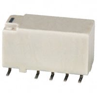
| 描述 | RELAY TELECOM DPDT 2A 3V |
| 产品分类 | |
| 品牌 | Panasonic Electric Works |
| 数据手册 | |
| 产品图片 |
|
| 产品型号 | TX2SA-L2-3V-Z |
| rohs | 无铅 / 符合限制有害物质指令(RoHS)规范要求 |
| 产品系列 | TX |
| 产品培训模块 | http://www.digikey.cn/PTM/IndividualPTM.page?site=cn&lang=zhs&ptm=17685 |
| 产品目录绘图 |
|
| 关闭电压(最小值) | - |
| 其它名称 | 255-3842-2 |
| 其它有关文件 | |
| 包装 | 带卷 (TR) |
| 安装类型 | 表面贴装 |
| 导通电压(最大值) | 2.25 VDC |
| 工作时间 | 4ms |
| 工作温度 | -40°C ~ 85°C |
| 开关电压 | 220VDC - 最小值 |
| 标准包装 | 500 |
| 特性 | 密封式 - 全部 |
| 端子类型 | 鸥翼型 |
| 线圈功率 | 200 mW |
| 线圈电压 | 3VDC |
| 线圈电流 | 66.7mA |
| 线圈电阻 | 45 欧姆 |
| 线圈类型 | 锁存,双线圈 |
| 继电器类型 | 电信 |
| 触头外形 | DPDT(2 C 型) |
| 触头材料 | Silver(Ag),Gold(Au) |
| 释放时间 | 4ms |
| 额定接触(电流) | 2A |


- 商务部:美国ITC正式对集成电路等产品启动337调查
- 曝三星4nm工艺存在良率问题 高通将骁龙8 Gen1或转产台积电
- 太阳诱电将投资9.5亿元在常州建新厂生产MLCC 预计2023年完工
- 英特尔发布欧洲新工厂建设计划 深化IDM 2.0 战略
- 台积电先进制程称霸业界 有大客户加持明年业绩稳了
- 达到5530亿美元!SIA预计今年全球半导体销售额将创下新高
- 英特尔拟将自动驾驶子公司Mobileye上市 估值或超500亿美元
- 三星加码芯片和SET,合并消费电子和移动部门,撤换高东真等 CEO
- 三星电子宣布重大人事变动 还合并消费电子和移动部门
- 海关总署:前11个月进口集成电路产品价值2.52万亿元 增长14.8%


PDF Datasheet 数据手册内容提取
TX TESTING New pin layout (LT type) added. Best seller with TX RELAYS broad lineup and AC 2000 V breakdown voltage. 3.Nominal operating power: High Destructive vibration resistance: sensitivity of 140mW 10 to 55 Hz (at double amplitude of By using the highly efficient polar 5 mm .197 inch) magnetic circuit “seesaw balance 8.Sealed construction allows mechanism”, a nominal operating automatic washing. power of 140 mW (minimum operating 9.A range of surface-mount types is power of 79 mW) has been achieved. also available 4.High contact capacity: 2 A 30 V DC SA: Low-profile surface-mount 5.Compact size terminal type Compliance with RoHS Directive 15.0(L) × 7.4(W) × 8.2(H) .591(L) × SL: High connection reliability surface- .291(W) × .323(H) mount terminal type 6.The use of gold-clad twin crossbar SS: Space saving surface-mount contacts ensures high contact terminal type FEATURES reliability. 1.2,000 V breakdown voltage between *We also offer a range of products contact and coil with AgPd contacts suitable for use TYPICAL APPLICATIONS The body block construction of the coil in low level load analog circuits that is sealed at formation offers a high (Max. 10V DC 10 mA). 1.Communications (xDSL, breakdown voltage of 2,000 V between *SX relays designed for low level Transmission) contact and coil, and 1,000 V between loads are also available. 2.Measurement open contacts. 7.Outstanding vibration and shock 3.Security 2.Outstanding surge resistance. resistance. 4.Home appliances, and audio/visual Surge breakdown voltage between Functional shock resistance: 750 m/s2 equipment open contacts: Destructive shock resistance: 5.Automotive equipment 1,500 V 10×160µ sec. (FCC part 68) 1,000 m/s2 6.Medical equipment Surge breakdown voltage between Functional vibration resistance: contact and coil: 10 to 55 Hz (at double amplitude of 2,500 V 2×10µ sec. (Bellcore) 3.3 mm .130 inch) ORDERING INFORMATION TX 2 Contact arrangement 2: 2 Form C Surface-mount availability Nil: Standard PC board terminal type or self-clinching terminal type SA: SA type SL: SL type SS: SS type Operating function Nil: Single side stable L: 1 coil latching L2: 2 coil latching LT: 2 coil latching Terminal shape Nil:Standard PC board terminal or surface-mount terminal H: Self-clinching terminal Nominal coil voltage (DC)* 1.5, 3, 4.5, 5, 6, 9, 12, 24, 48V Contact material Nil:Standard contact (Ag+Au clad) 1: AgPd contact (low level load); AgPd+Au clad (stationary), AgPd (movable) Packing style Nil:Tube packing X: Tape and reel (picked from 1/3/4/5-pin side) Z: Tape and reel packing (picked from the 8/9/10/12-pin side) Notes:1. *48 V coil type: Single side stable only 2. In case of 5 V transistor drive circuit, it is recommended to use 4.5 V type relay. All Rights Reserved © COPYRIGHT Panasonic Electric Works Co., Ltd.
TX TYPES 1. Standard PC board terminal Contact Nominal coil Single side stable 1 coil latching 2 coil latching (L2) 2 coil latching (LT) arrangement voltage Part No. Part No. Part No. Part No. 1.5V DC TX2-1.5V TX2-L-1.5V TX2-L2-1.5V TX2-LT-1.5V 3V DC TX2-3V TX2-L-3V TX2-L2-3V TX2-LT-3V 4.5V DC TX2-4.5V TX2-L-4.5V TX2-L2-4.5V TX2-LT-4.5V 5V DC TX2-5V TX2-L-5V TX2-L2-5V TX2-LT-5V 2 Form C 6V DC TX2-6V TX2-L-6V TX2-L2-6V TX2-LT-6V 9V DC TX2-9V TX2-L-9V TX2-L2-9V TX2-LT-9V 12V DC TX2-12V TX2-L-12V TX2-L2-12V TX2-LT-12V 24V DC TX2-24V TX2-L-24V TX2-L2-24V TX2-LT-24V 48V DC TX2-48V — — — Standard packing: Tube: 40 pcs.; Case: 1,000 pcs. Note: Please add “-1” to the end of the part number for AgPd contacts (low level load). 2. self-clinching terminal Contact Nominal coil Single side stable 1 coil latching 2 coil latching (L2) 2 coil latching (LT) arrangement voltage Part No. Part No. Part No. Part No. 1.5V DC TX2-H-1.5V TX2-L-H-1.5V TX2-L2-H-1.5V TX2-LT-H-1.5V 3V DC TX2-H-3V TX2-L-H-3V TX2-L2-H-3V TX2-LT-H-3V 4.5V DC TX2-H-4.5V TX2-L-H-4.5V TX2-L2-H-4.5V TX2-LT-H-4.5V 5V DC TX2-H-5V TX2-L-H-5V TX2-L2-H-5V TX2-LT-H-5V 2 Fom C 6V DC TX2-H-6V TX2-L-H-6V TX2-L2-H-6V TX2-LT-H-6V 9V DC TX2-H-9V TX2-L-H-9V TX2-L2-H-9V TX2-LT-H-9V 12V DC TX2-H-12V TX2-L-H-12V TX2-L2-H-12V TX2-LT-H-12V 24V DC TX2-H-24V TX2-L-H-24V TX2-L2-H-24V TX2-LT-H-24V 48V DC TX2-H-48V — — — Standard packing: Tube: 40 pcs.; Case: 1,000 pcs. Note: Please add “-1” to the end of the part number for AgPd contacts (low level load). 3. Surface-mount terminal 1) Tube packing Contact Nominal coil Single side stable 1 coil latching 2 coil latching (L2) 2 coil latching (LT) arrangement voltage Part No. Part No. Part No. Part No. 1.5V DC TX2S(cid:1)-1.5V TX2S(cid:1)-L-1.5V TX2S(cid:1)-L2-1.5V TX2S(cid:1)-LT-1.5V 3V DC TX2S(cid:1)-3V TX2S(cid:1)-L-3V TX2S(cid:1)-L2-3V TX2S(cid:1)-LT-3V 4.5V DC TX2S(cid:1)-4.5V TX2S(cid:1)-L-4.5V TX2S(cid:1)-L2-4.5V TX2S(cid:1)-LT-4.5V 5V DC TX2S(cid:1)-5V TX2S(cid:1)-L-5V TX2S(cid:1)-L2-5V TX2S(cid:1)-LT-5V 2c 6V DC TX2S(cid:1)-6V TX2S(cid:1)-L-6V TX2S(cid:1)-L2-6V TX2S(cid:1)-LT-6V 9V DC TX2S(cid:1)-9V TX2S(cid:1)-L-9V TX2S(cid:1)-L2-9V TX2S(cid:1)-LT-9V 12V DC TX2S(cid:1)-12V TX2S(cid:1)-L-12V TX2S(cid:1)-L2-12V TX2S(cid:1)-LT-12V 24V DC TX2S(cid:1)-24V TX2S(cid:1)-L-24V TX2S(cid:1)-L2-24V TX2S(cid:1)-LT-24V 48V DC TX2S(cid:1)-48V — — — (cid:1): For each surface-mounted terminal identification, input the following letter. SA type: A, SL type: L, SS type: S Standard packing: Tube: 40 pcs.; Case: 1,000 pcs. Note: Please add “-1” to the end of the part number for AgPd contacts (low level load). 2) Tape and reel packing Contact Nominal coil Single side stable 1 coil latching 2 coil latching (L2) 2 coil latching (LT) arrangement voltage Part No. Part No. Part No. Part No. 1.5V DC TX2S(cid:1)-1.5V-Z TX2S(cid:1)-L-1.5V-Z TX2S(cid:1)-L2-1.5V-Z TX2S(cid:1)-LT-1.5V-Z 3V DC TX2S(cid:1)-3V-Z TX2S(cid:1)-L-3V-Z TX2S(cid:1)-L2-3V-Z TX2S(cid:1)-LT-3V-Z 4.5V DC TX2S(cid:1)-4.5V-Z TX2S(cid:1)-L-4.5V-Z TX2S(cid:1)-L2-4.5V-Z TX2S(cid:1)-LT-4.5V-Z 5V DC TX2S(cid:1)-5V-Z TX2S(cid:1)-L-5V-Z TX2S(cid:1)-L2-5V-Z TX2S(cid:1)-LT-5V-Z 2 Form C 6V DC TX2S(cid:1)-6V-Z TX2S(cid:1)-L-6V-Z TX2S(cid:1)-L2-6V-Z TX2S(cid:1)-LT-6V-Z 9V DC TX2S(cid:1)-9V-Z TX2S(cid:1)-L-9V-Z TX2S(cid:1)-L2-9V-Z TX2S(cid:1)-LT-9V-Z 12V DC TX2S(cid:1)-12V-Z TX2S(cid:1)-L-12V-Z TX2S(cid:1)-L2-12V-Z TX2S(cid:1)-LT-12V-Z 24V DC TX2S(cid:1)-24V-Z TX2S(cid:1)-L-24V-Z TX2S(cid:1)-L2-24V-Z TX2S(cid:1)-LT-24V-Z 48V DC TX2S(cid:1)-48V-Z — — — Standard packing: Tape and reel: 500 pcs.; Case: 1,000 pcs. Notes:1.Tape and reel packing symbol “-Z” is not marked on the relay. “X” type tape and reel packing (picked from 1/2/3/4-pin side) is also available. 2.Please add “-1” to the end of the part number for AgPd contacts (low level load). All Rights Reserved © COPYRIGHT Panasonic Electric Works Co., Ltd.
TX RATING 1. Coil data 1) Single side stable Nominal operating Nominal coil Pick-up voltage Drop-out voltage Coil resistance Nominal operating Max. applied voltage voltage (at 20°C 68°F) (at 20°C 68°F) [±10%] c(autr r2e0n°tC 68°F) [±10%] (at 20°C 68°F) power (at 20°C 68°F) 1.5V DC 93.8mA 16Ω 3V DC 46.7mA 64.3Ω 4.5V DC 31mA 145Ω 5V DC 28.1mA 178Ω 150%V of 6V DC 75%V or less of 10%V or more of 23.3mA 257Ω 140mW nominal voltage nominal voltage* nominal voltage* 9V DC (Initial) (Initial) 15.5mA 579Ω 12V DC 11.7mA 1,028Ω 24V DC 5.8mA 4,114Ω 48V DC 5.6mA 8,533Ω 270mW 120%V of nominal voltage 2) 1 coil latching Nominal operating Nominal coil Set voltage Reset voltage Coil resistance Nominal operating Max. applied voltage voltage (at 20°C 68°F) (at 20°C 68°F) [±10%] c(autr r2e0n°tC 68°F) [±10%] (at 20°C 68°F) power (at 20°C 68°F) 1.5V DC 66.7mA 22.5Ω 3V DC 33.3mA 90Ω 4.5V DC 22.2mA 202.5Ω 5V DC 75%V or less of 75%V or less of 20mA 250Ω 150%V of nominal voltage* nominal voltage* 100mW 6V DC (Initial) (Initial) 16.7mA 360Ω nominal voltage 9V DC 11.1mA 810Ω 12V DC 8.3mA 1,440Ω 24V DC 4.2mA 5,760Ω 3) 2 coil latching (L2, LT) Nominal operating Coil resistance Nominal operating Novmoilntaagl ecoil (aSt e2t0 v°Col t6a8g°eF ) (Raet s2e0t° Cvo 6lt8a°gFe) [±10%] c(autr r2e0n°tC 68°F) [±10%] (at 20°C 68°F) power Max(a. at p2p0l°iCed 6 v8o°lFtage Set coil Reset coil Set coil Reset coil Set coil Reset coil 1.5V DC 133.9mA 133.9mA 11.2Ω 11.2Ω 3V DC 66.7mA 66.7mA 45Ω 45Ω 4.5V DC 44.5mA 44.5mA 101.2Ω 101.2Ω 5V DC 75%V or less of 75%V or less of 40mA 40mA 125Ω 125Ω 150%V of nominal voltage* nominal voltage* 200mW 200mW 6V DC (Initial) (Initial) 33.3mA 33.3mA 180Ω 180Ω nominal voltage 9V DC 22.2mA 22.2mA 405Ω 405Ω 12V DC 16.7mA 16.7mA 720Ω 720Ω 24V DC 8.3mA 8.3mA 2,880Ω 2,880Ω *Pulse drive (JIS C 5442-1986) All Rights Reserved © COPYRIGHT Panasonic Electric Works Co., Ltd.
TX 2. Specifications Characteristics Item Specifications Arrangement 2 Form C Initial contact resistance, max. Max. 100 mΩ (By voltage drop 6 V DC 1A) Contact Standard contact: Ag+Au clad, Contact material AgPd contact (low level load): AgPd+Au clad (stationary), AgPd (movable) Nominal switching capacity Standard contact: 2 A 30 V DC, AgPd contact: 1 A 30 V DC (resistive load) Max. switching power Standard contact: 60 W (DC), AgPd contact: 30 W (DC) (resistive load) Max. switching voltage 220V DC Max. switching current Standard contact: 2 A, AgPd contact: 1 A Rating Min. switching capacity (Reference value)*1 10µA 10mV DC Single side stable 140 mW (1.5 to 24 V DC), 270 mW (48 V DC) Nominal operating 1 coil latching 100 mW (1.5 to 24 V DC) power 2 coil latching 200 mW (1.5 to 24 V DC) Min. 1,000MΩ (at 500V DC) Insulation resistance (Initial) Measurement at same location as “Initial breakdown voltage” section. Between open contacts 1,000 Vrms for 1min. (Detection current: 10mA) Breakdown voltage Between contact and coil 2,000 Vrms for 1min. (Detection current: 10mA) (Initial) Between contact sets 1,000 Vrms for 1min. (Detection current: 10mA) Surge breakdown Between open contacts 1,500 V (10×160µs) (FCC Part 68) Electrical characteristics voltage (Initial) Between contacts and coil 2,500 V (2×10µs) (Telcordia) Temperature rise (at 20°C 68°F) Max. 50°C (By resistive method, nominal coil voltage applied to the coil; contact carrying current: 2A.) Operate time [Set time] (at 20°C 68°F) Max. 4 ms [Max. 4 ms] (Nominal coil voltage applied to the coil, excluding contact bounce time.) Release time [Reset time] (at 20°C 68°F) Max. 4 ms [Max. 4 ms] (Nominal coil voltage applied to the coil, excluding contact bounce time.) (without diode) Functional Min. 750 m/s2 (Half-wave pulse of sine wave: 6 ms; detection time: 10µs.) Shock resistance Mechanical Destructive Min. 1,000 m/s2 (Half-wave pulse of sine wave: 6 ms.) characteristics Functional 10 to 55 Hz at double amplitude of 3.3 mm (Detection time: 10µs.) Vibration resistance Destructive 10 to 55 Hz at double amplitude of 5 mm Mechanical Min. 108 (at 180 cpm) Expected life Electrical Min. 105 (2 A 30 V DC resistive), 5×10⁵ (1 A 30 V DC resistive) (at 20 cpm) Ambient temperature: –40°C to +85°C (up to 24 V coil) –40°F to +185°F (up to 24 V coil) Conditions for operation, transport and storage*2 [–40°C to +70°C (48 V coil) –40°F to +158°F (48 V coil)]; Conditions Humidity: 5 to 85% R.H. (Not freezing and condensing at low temperature) Max. operating speed (at rated load) 20 cpm Unit weight Approx. 2 g .071 oz Notes:*1 This value can change due to the switching frequency, environmental conditions, and desired reliability level, therefore it is recommended to check this with the actual load. (AgPd contact type is available for low level load switching [10V DC, 10mA max. level]) *2 Refer to 6. Conditions for operation, transport and storage mentioned in AMBIENT ENVIRONMENT. REFERENCE DATA 1. Maximum switching capacity 2. Life curve 3. Mechanical life Tested sample: TX2-5V, 10 pcs. Operating speed: 180 cpm V100 % 3.0 e, 90 g Switching current, A 0012....4500 DC resistive load ×4of operations 10105320000 3re0sVis DtivCe load gainst the rated volta 4567800000 Pick-up voltage MMainx.. 00..23 No. 10 Ratio a 2300 Drop-out voltage Max. 10 Min. 0 0 0 20 30 50 100 200300 1.0 2.0 10 100 1,000 10,000 Contact voltage, V Switching current, A No. of operations, ×104 4. Electrical life (2A 30V DC resistive load) 5-(1). Coil temperature rise Tested sample: TX2-5V, 6 pcs. Tested sample: TX2-5V, 6 pcs. Operating speed: 20 cpm Point measured: Inside the coil Change of pick-up and drop-out voltage Change of contact resistance Ambient temperature: 25°C 77°F, 85°C 185°F Ratio against the rated voltage, %V1234567890000000000 DPriocpk--uopu tv vooltlataggee MMMaianxx... ΩContact resistance, m1234567890000000000 MMainx.. °Temperature rise, C245367000000 ++220028AAAA55°°CC++7178°5F°F 10 Min. 10 10 0 0 0 1 2 3 4 5 6 7 8 9 10 1 2 3 4 5 6 7 8 9 10 100 110 120 130 140 150 No. of operations, ×104 No. of operations, ×104 Coil applied voltage, % All Rights Reserved © COPYRIGHT Panasonic Electric Works Co., Ltd.
TX 5-(2). Coil temperature rise 6-(1). Operate and release time (with diode) 6-(2). Operate and release time (without diode) Tested sample: TX2-48V, 6 pcs. Tested sample: TX2-5V, 10 pcs. Tested sample: TX2-5V, 10 pcs. Point measured: Inside the coil Ambient temperature: 25°C 77°F, 70°C 158°F °Temperature rise, C245367000000 ++220027AAAA50°°CC++7175°8F°F Operate and release time, ms 2453 MMMMaaiinnxx.... ORepleeraastee ttiimmee Operate and release time, ms2453 MMMMaaiinxnx.... ORepleeraastee ttiimmee 1 1 10 0 0 0 100 110 120 130 140 150 70 80 90 100 110 120 70 80 90 100 110 120 Coil applied voltage, % Coil applied voltage, %V Coil applied voltage, %V 7. Ambient temperature characteristics 8-(1). High frequency characteristics 8-(2). High frequency characteristics Tested sample: TX2-5V, 5 pcs. (Isolation) (Insertion loss) Tested sample: TX2-12V, 2 pcs. Tested sample: TX2-12V, 2 pcs. % e, 40 ng Drop-out –40 –20 0 Rate of cha220A0m4b0vieonltt6a t0gPeemickp8-e0xxurpa tvuorelta, g°Ce Isolation, dB100 nsertion loss, dB 10..08 I 50 0.6 –20 0.4 –40 0.2 10 100 1,000 10 100 1,000 Frequency, MHz Frequency, MHz 9 Malfunctional shock (single side stable) 10-(1). Influence of adjacent mounting 10-(2). Influence of adjacent mounting Tested sample: TX2-5V, 6 pcs. Tested sample: TX2-12V, 6 pcs. Tested sample: TX2-12V, 6 pcs. 1YY0Z'0'0mXZ/s2XX'1000m/s2Y DEneeernge1i0zrZg0e0idzm ec/sdo2 ncdointidointion Rate of change, %–505 Pick-up voltage ONONON Rate of change, %–505 Pick-up voltage OONNON 1000Zm'/s2 Y1'000m/s2 10X0'0m/s2 Rate of change, %–055 Drop-out voltage OFOFFFOFF Rate of change, %–505 Drop-out voltage OOFFFFOFF 0 2 4 6 8 10 0 2 4 6 8 10 .079.157.236.315.394 .079.157.236.315.394 Inter-relay distance , mminch Inter-relay distance , mminch 11. Pulse dialing test Tested sample: TX2-5V, 6 pcs. (35 mA 48 V DC wire spring relay load) Change of pick-up and drop-out voltage Change of contact resistance 100 100 V % 90 90 Cir4c+–8uVi tDC0µ.0F8445588 ΩΩ0µ.0F8 43TX o against the rated voltage, 345678000000 DPriocpk--ouupt vvoollttaaggee MMMaainxx... ΩContact resistance, m 345678000000 MMainx.. Wire spring relay Rati 20 Min. 20 10 10 0 0 10 20 30 40 50 10 20 30 40 50 No. of operation, ×104 No. of operations, ×104 Note: Data of surface-mount type are the same as those of PC board terminal type. All Rights Reserved © COPYRIGHT Panasonic Electric Works Co., Ltd.
TX DIMENSIONS (mm inch) The CAD data of the products with a CAD Data mark can be downloaded from: http://panasonic-electric-works.net/ac 1. Standard PC board terminal and Self clinching terminal CAD Data Single side stable and 1 coil latching type 2 coil latching type (L2, LT) External dimensions External dimensions Standard PC board terminal Standard PC board terminal 15.00 7.40 15.00 7.40 .591 .291 .591 .291 .00.26658.3.2203 .00.2665 8.3.2203 1.0.00..12545005 5.2.0080 2.1.5040 3.1.5308 5.2.0080 0.0.2150 1.0.00..12545005 5.2.0080 2.1.5040 3.1.5308 5.2.0080 0.0.2150 Self clinching terminal Self clinching terminal 15.00 7.40 15.00 7.40 .591 .291 .591 .291 .00.26658.3.2203 .00.26658.3.2203 1.0.00..12545005 5.2.0080 2.1.5040 3.1.5308 5.2.0080 0.0.2150 1.0.00..12545005 5.2.0080 2.1.5040 ((1.0.1455))3.1.5308 5.2.0080 0.0.2150 General tolerance: ±0.3 ±.012 General tolerance: ±0.3 ±.012 PC board pattern Schematic (Bottom view) PC board pattern Schematic (Bottom view) (Bottom view) Single side stable 1 coil latching (Bottom view) 2 coil latching (L2) 2 coil latching (LT) 2.1.5040 1.04.0106 +1 3 4 5 –1 3 4 5 2.1.5040 1.520.70 +1 3 4 5 –6 +1 3 4 5 6+ 5.08 5.08 + – .200 – + .200 – – 12 10 9 8 12 10 9 8 12 10 9 8 7 12 10 9 8 7 88--1.0.03 9d idai.a. Direction indication Direction indication 1100--1.0.03 9d idai.a. Direction indication Direction indication Tolerance: ±0.1 ±.004 (Deenergized condition) (Reset condition) Tolerance: ±0.1 ±.004 (Reset condition) (Reset condition) 2. Surface-mount terminal CAD Data External dimensions (General tolerance: ±0.3 ±.012) Suggested mounting pad (Top view) (Tolerance: ±0.1 ±.004) Type Single side stable and Single side stable and 2 coil latching type (L2, LT) 2 coil latching type (L2, LT) 1 coil latching type 1 coil latching type SA type .51951 8.3.223 .383.14 .279.41 0.25 .51951 8.3.223 .383.14 .279.41 0.25 .31.2146.0319 5.2.0080 .21.0504 .31.2146.0319 .52.0008 .21.0504 0.5 0.0.6256 5.2.0080 .010 0.5 0.0.6256 5.2.0080 .010 7.2.2845 7.2.2845 .020 5.08 2.54 9.4±0.5 .020 5.08 2.54 9.4±0.5 .200 .100 .370±.020 .200 .100 .370±.020 .51951 8.3.223Ma.x3.1904 .72.941 .51951 8.3.223Ma.x3.1904 .72.941 .31.2146.0319 5.2.0080 .21.0504 .31.2146.0319 .52.0008 .21.0504 SL type 0.25 0.25 0.65 .010 0.65 .010 7.24 7.24 .026 5.08 .026 5.08 .285 .285 0.0.520 5.2.0080 2.1.5040 .397..042±±0.000.250 0.0.520 5.2.0080 2.1.5040 .397..042±±0.000.250 .51951 .72.941 .51951 .72.941 5.08 2.54 8.3.223Ma.x3.1904 8.3.223Ma.x3.1904 .20.8156.0319 .200 .100 .20.8156.0319 .52.0008 .21.0504 SS type 0.25 0.25 0.0.6256 5.08 .010 0.0.6256 5.08 .010 6.2.2446 6.2.2446 0.0.520 .52.0008 2.1.5040 .279..412±±00.00.520 0.0.520 .52.0008 2.1.5040 .279..412±±00.00.520 Schematic (Top view) Single side stable 1 coil latching 2 coil latching (L2) 2 coil latching (LT) –12 10 9 8 +12 10 9 8 –12 10 9 8 7– 12 10 9 8 7 + – + – + – + + 1 3 4 5 1 3 4 5 1 3 4 5 6 1 3 4 5 6 Direction indication Direction indication Direction indication Direction indication (Deenergized condition) (Reset condition) (Reset condition) (Reset condition) All Rights Reserved © COPYRIGHT Panasonic Electric Works Co., Ltd.
TX NOTES 1. Packing style 2. Automatic insertion 1) The relay is packed in a tube with the To maintain the internal function of the relay orientation mark on the left side, as relay, the chucking pressure should not shown in the figure below. exceed the values below. Chucking pressure in the direction A: Orientation (indicates PIN No.1) stripe 4.9 N {500gf} or less Chucking pressure in the direction B: 9.8 N {1 kgf} or less Chucking pressure in the direction C: Stopper (gray) Stopper (green) 9.8 N {1 kgf} or less 2) Tape and reel packing (surface-mount C B terminal type) A (1) Tape dimensions (i) SA type mm inch R(Ze tlaypy ep)olarity bar.015.95+ + 00.00.014ddiaia...027.09 .41.507 1.0.7659 .001.46 Please chuck the portion. C Avoid chucking the center of the relay. A B 11.5 .453 15.5 In addition, excessive chucking pressure .610 to the pinpoint of the relay should be Relays 1.663.00 10.0.D394 2.944.05±±0.0.312 9.2±0.2 avoided. .362±.008 Tape coming out direction (ii) SL type For general cautions for use, mm inch please refer to the “Cautions for use of Signal Relays” or “General R(Ze tlaypy ep)olarity bar .015.95+ + 00.00.014ddiaia...20.709 .41.507 1.0.7659 .00.146 Application Guidelines”. 11.5 .453 15.5 .610 16.0 24.0±0.3 Relays .630 1.309.04 .945±.0121.402.85±±0.0.208 Tape coming out direction (iii) SS type mm inch R(Ze tlaypy ep)olarity bar .015.59+ + 00.00.014ddiaia...20.709 .41.507 .10.6795 .00.146 11.5 .453 15.5 .610 16.0 8.0 24.0±0.3 Relays .630 .315.945±.01210.8±0.2 .425±.008 Tape coming out direction (2) Dimensions of plastic reel mm inch 2.0 .079 380 dia. 13 dia. 21 dia. 14.961 dia. .512 dia. .827 dia. 80 dia. 3.150 dia. All Rights Reserved © COPYRIGHT Panasonic Electric Works Co., Ltd.
Mouser Electronics Authorized Distributor Click to View Pricing, Inventory, Delivery & Lifecycle Information: P anasonic: TX2SA-L2-3V-Z TX2-1.5V TX2-12V-1 TX2-24V-1 TX2-4.5V-1 TX2-5V-1 TX2-6V TX2-L-1.5V TX2-L-12V TX2- L2-1.5V TX2-L2-12V-1 TX2-L2-3V TX2-L2-3V-1 TX2-L2-4.5V-1 TX2-L-24V TX2-L-24V-1 TX2-L2-6V TX2-L-5V-1 TX2-L-6V TX2SA-1.5V TX2SA-1.5V-X TX2SA-1.5V-Z TX2SA-12V-X TX2SA-24V-X TX2SA-3V-X TX2SA-4.5V-1 TX2SA-4.5V-1-Z TX2SA-4.5V-X TX2SA-48V TX2SA-48V-X TX2SA-48V-Z TX2SA-5V-1 TX2SA-6V TX2SA-6V-X TX2SA-6V-Z TX2SA-9V-X TX2SA-9V-Z TX2SA-L-1.5V TX2SA-L-1.5V-X TX2SA-L-1.5V-Z TX2SA-L-12V TX2SA-L- 12V-X TX2SA-L-12V-Z TX2SA-L2-1.5V TX2SA-L2-1.5V-X TX2SA-L2-1.5V-Z TX2SA-L2-12V-1 TX2SA-L2-12V-X TX2SA-L2-12V-Z TX2SA-L2-24V TX2SA-L2-24V-1 TX2SA-L2-24V-1-X TX2SA-L2-24V-1-Z TX2SA-L2-24V-X TX2SA-L2-24V-Z TX2SA-L2-3V-X TX2SA-L2-4.5V-X TX2SA-L2-4.5V-Z TX2SA-L-24V TX2SA-L-24V-X TX2SA-L- 24V-Z TX2SA-L2-5V-1 TX2SA-L2-5V-1-Z TX2SA-L2-5V-X TX2SA-L2-6V TX2SA-L2-6V-Z TX2SA-L2-9V TX2SA- L2-9V-X TX2SA-L2-9V-Z TX2SA-L-3V TX2SA-L-3V-1 TX2SA-L-3V-1-Z TX2SA-L-3V-X TX2SA-L-3V-Z TX2SA-L- 4.5V TX2SA-L-4.5V-1 TX2SA-L-4.5V-1-Z TX2SA-L-4.5V-X TX2SA-L-5V TX2SA-L-5V-X TX2SA-L-5V-Z TX2SA-L- 6V TX2SA-L-6V-X TX2SA-L-6V-Z TX2SA-L-9V TX2SA-L-9V-X TX2SA-L-9V-Z TX2SL-1.5V-X TX2SL-1.5V-Z TX2SL-12V-X TX2SL-3V-X TX2SL-4.5V-X TX2SL-48V-X TX2SL-5V-1 TX2SL-6V-X TX2SL-6V-Z TX2SL-9V-1 TX2SL-9V-X TX2SL-L-1.5V TX2SL-L-1.5V-X