ICGOO在线商城 > 开发板,套件,编程器 > 评估和演示板和套件 > TSW4200
- 型号: TSW4200
- 制造商: Texas Instruments
- 库位|库存: xxxx|xxxx
- 要求:
| 数量阶梯 | 香港交货 | 国内含税 |
| +xxxx | $xxxx | ¥xxxx |
查看当月历史价格
查看今年历史价格
TSW4200产品简介:
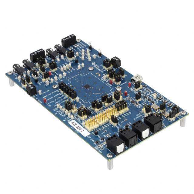
ICGOO电子元器件商城为您提供TSW4200由Texas Instruments设计生产,在icgoo商城现货销售,并且可以通过原厂、代理商等渠道进行代购。 TSW4200价格参考。Texas InstrumentsTSW4200封装/规格:评估和演示板和套件, ADS62P49, DAC3283 ADC/DAC for Xilinx Virtex VI FPGA Interface Evaluation Board。您可以下载TSW4200参考资料、Datasheet数据手册功能说明书,资料中有TSW4200 详细功能的应用电路图电压和使用方法及教程。
| 参数 | 数值 |
| 产品目录 | 编程器,开发系统 |
| 描述 | DEV PLATFORM XILINX VIRTEX VI |
| 产品分类 | |
| 品牌 | Texas Instruments |
| 数据手册 | 点击此处下载产品Datasheet点击此处下载产品Datasheethttp://www.ti.com/lit/pdf/slwu071 |
| 产品图片 |
|
| 产品型号 | TSW4200 |
| rohs | 无铅 / 符合限制有害物质指令(RoHS)规范要求 |
| 产品系列 | - |
| 主要属性 | - |
| 主要用途 | 接口,用于 Xilinx Virtex VI FPGA 的 ADC/DAC |
| 使用的IC/零件 | ADS62P49,DAC3283 |
| 其它名称 | 296-31330 |
| 嵌入式 | 否 |
| 所含物品 | 2 块板,2 块适配卡 |
| 标准包装 | 1 |
| 辅助属性 | - |



- 商务部:美国ITC正式对集成电路等产品启动337调查
- 曝三星4nm工艺存在良率问题 高通将骁龙8 Gen1或转产台积电
- 太阳诱电将投资9.5亿元在常州建新厂生产MLCC 预计2023年完工
- 英特尔发布欧洲新工厂建设计划 深化IDM 2.0 战略
- 台积电先进制程称霸业界 有大客户加持明年业绩稳了
- 达到5530亿美元!SIA预计今年全球半导体销售额将创下新高
- 英特尔拟将自动驾驶子公司Mobileye上市 估值或超500亿美元
- 三星加码芯片和SET,合并消费电子和移动部门,撤换高东真等 CEO
- 三星电子宣布重大人事变动 还合并消费电子和移动部门
- 海关总署:前11个月进口集成电路产品价值2.52万亿元 增长14.8%


PDF Datasheet 数据手册内容提取
User's Guide SLWU071C–April2010–RevisedNovember2012 TSW4200 Demonstration Kit Contents 1 Introduction .................................................................................................................. 2 2 Software ...................................................................................................................... 5 3 QuickSetup .................................................................................................................. 6 4 AdapterReference .......................................................................................................... 7 5 NotesonInterfacingwithXilinx7-SeriesFPGA ........................................................................ 7 ListofFigures 1 TSW4200DemonstrationKit ............................................................................................. 2 2 DAC3283EVMBlockDiagram............................................................................................ 3 3 ADS62P49EVMBlockDiagram.......................................................................................... 4 4 DAC3283EVMSoftwareConfiguration.................................................................................. 6 ListofTables 1 TSW4200DemonstrationKitReferenceMaterials..................................................................... 2 2 TSW4200-DACDefaultJumperSetting ................................................................................. 4 3 TSW4200-ADCDefaultJumperSetting ................................................................................. 5 SLWU071C–April2010–RevisedNovember2012 TSW4200DemonstrationKit 1 SubmitDocumentationFeedback Copyright©2010–2012,TexasInstrumentsIncorporated
Introduction www.ti.com 1 Introduction 1.1 Overview Thisistheuser’sguidefortheTSW4200DemonstrationKit.ThekitincludestwoEVMs:TSW4200-DAC andTSW4200-ADC,andtheyprovideevaluationtoTI’sDAC3283andADS62P49,respectively.Through theincludedFMCadapterboards,theEVMsareideallysuitedformatingwithaFPGAdevelopmentboard toevaluatetheDACandtheADCasabasictransmitterandreceiversystem.Formoreinformation regardingtheindividualdeviceorEVM,refertoTable1fortherespectivedevice’sdatasheetandEVM user’sguide. Table1.TSW4200DemonstrationKitReferenceMaterials Device DataSheet EVM User'sGuide TSW4200-DAC DAC3283 SLAS693 DAC328xEVM SLAU311 TSW4200-ADC ADS62P49 SLAS635 ADS62PxxEVM SLAU237 TheincludedFMCadaptersaretheFMC-DAC-AdapterandtheFMC-ADC-Adapter.Theyareatypeof passiveinterconnectboardenablingdirectconnectionoftheoutputofTI’sLVDShighspeedDACsor ADCstoastandardFMCinterconnectheader.TheFMCinterconnectheaderisatypicalinputonthe latestXilinxFPGAEVMs.TheTSW4200-DACEVMusestheFMC-DAC-Adapter,andtheTSW4200-ADC usestheFMC-ADC-Adapter. Note:Usetheadapterswiththelatestrevisionupdate: FMC-DAC-Adapter(rev.Aorlater) FMC-ADC-Adapter(rev.Corlater) HSMC-ADC-Bridge(rev.Borlater) 1.2 TSW2400 Demonstration Kit Block Diagram Figure1showstheconfigurationsoftheTSW4200-DACandTSW4200-ADCEVMwiththeFPGA developmentboard.Section3coversthesetupinformationoftheEVMs. FPGADevelopment Board LVDS Data OUT IN 6V Power Wall Outlet Wall Power ChA Outlet Brick 5V Power J6 J5 J8 Power ed ed Brick J3 DAC3283 erfacBoar erfacBoar ADS62P49J6 J17 nter nter J1 ACIdapt DCIdapt J19 DA AA J10 J3 USB J11 J16 Ref CLK USB TSW4200-DAC (optional) TSW4200-ADC Ch B Figure1.TSW4200DemonstrationKit 2 TSW4200DemonstrationKit SLWU071C–April2010–RevisedNovember2012 SubmitDocumentationFeedback Copyright©2010–2012,TexasInstrumentsIncorporated
www.ti.com Introduction 1.3 TSW4200-DAC Configuration TCXO Modulator Reference CLK CDCE62005 FPGACLK Ext.CLK TRF3720 J21 RF J11 OSTR_CLK DAC_CLK + J1 DATA Filter+Transformer Output DAC328x _ Data_CLK Filter Bypass orTransformer only Output FRAME_CLK + J3 _ J6 J24 RF Power TRF3703-xx 6V Only Supply TRF3704 Circuits J27 LO OptionalTRF3703-xx orTRF3704Output Figure2.DAC3283EVMBlockDiagram 1. TheTSW4200-DACkitisaDAC3283EVMconfiguredasfollow: (a)PowerSupplyOption:Thekitincludesa6-VpowersupplyinputtopowersupplyjackJ6.For properEVMoperationandtopreventdamagetotheEVM,onlyusea6-Vpowersupply. (b)AnalogOutputOption:Theon-boardDAC3283hasdual-channeloutputsthatgothroughafilter networkandtransformertoJ3(Ch.A)andJ1(Ch.B). (c) ClockOption:Theon-boardCDCDE62005providesclockstoalltheon-boarddevices. (i) ThedefaultDACclockisconfiguredat614.4MHz.TheDACinterpolation,FPGAclock (TSW3100CLK),andtheFIFOOSTRclockcanbeconfiguredbasedonthedatarate,FPGA configuration,andsystemrequirement.Formoreinformation,pleaserefertotheDAC3283 datasheet. (ii) TheTSW4200-DAChasaclockoutputatJ11thatprovidesthereferenceclockforthe CDCE72010ontheTSW4200-ADCatJ19.Thedefaultreferenceclockshouldbeconfigured as19.2MHz. 2. TheEVMhasthedefaultjumpersettinglistedonTable2. 3. Formoredetails,refertotheDAC3283EVMUser’sGuide(SLAU311). SLWU071C–April2010–RevisedNovember2012 TSW4200DemonstrationKit 3 SubmitDocumentationFeedback Copyright©2010–2012,TexasInstrumentsIncorporated
Introduction www.ti.com Table2.TSW4200-DACDefaultJumperSetting Jumper DefaultPosition Purpose JP22 2-3 CDCE62005(U4)externalreferenceclockbias JP19 Shorted EnableTCXO(U7) JP9 1-2 DAC3283(U1)TXENABLE JP20 1-2 CDCE62005(U4)powerdown JP21 1-2 CDCE62005(U4)referenceselect JP13 2-3 TRF3720(U3)powersave JP17 1-2(TRF3720) TRF3720(U3)orTRF3703(U10)PowerPath 1.4 TSW4200-ADC Configuration Optional Ext.CLK CLK Input J19 Ref.CLK CDCE72010 491.52MHz 245.76MHz /2 + VCXO Crystal Filter _ J6 + Transformers Coupled _ ADS62Pxx DATA Input Circuit Data_CLK J3 + _ OptionalAmplifier Path J17 Power 5V Only Supply Circuits Figure3.ADS62P49EVMBlockDiagram 1. TSW4200-ADCConfiguration: (a)PowerSupplyOption:Thekitincludesa5-VpowersupplyinputtopowersupplyjackJ17.For properEVMoperationandtopreventdamagetotheEVM,onlyusea5-Vpowersupply. (b)AnalogInputOption:Theon-boardADS62P49hasdual-channeltransformer-coupledinputsfrom J3(Ch.A)andJ6(Ch.B). (c) ClockOption:Theon-boardCDCE72010providesacrystal-filteredLVCMOSclockat245.76MHz totheon-boardADS62P49.Thereferenceclockinputof19.2MHztotheTSW4200-ADCisatJ19. TheCDCE72010isconfiguredinPLLmodebydefaultusingtheon-board491.52-MHzVCXO.The CDCE72010’soutputhasthedividerconfiguredtobedivide-by-2,dividingthe491.52-MHzVCXO clocktotherequired245.76-MHzclock. 2. TheEVMhasthedefaultjumpersettinglistedonTable3. 3. Formoredetails,refertotheADS62PXXEVMUser’sGuide(SLAU237). 4 TSW4200DemonstrationKit SLWU071C–April2010–RevisedNovember2012 SubmitDocumentationFeedback Copyright©2010–2012,TexasInstrumentsIncorporated
www.ti.com Software Table3.TSW4200-ADCDefaultJumperSetting Jumper DefaultPosition Purpose JP11 1-2(parallel) ADS62P49(U2)parallelorserialmodeoption JP8 1-2(parallel) SCLKparallelorserialmodeoption JP12 1-2(0dBgain,int.ref.) SCLKparallelmodeselect JP9 1-2(parallel) SDATAparallelorserialmodeoption JP13 Open SDATAparallelmodeoption JP10 1-2(parallel) SENparallelorserialmodeselect JP14 1-2(2'scomplement&DDRLVDS) SENparallelmodeoption JP20 1-2 CDCE72010(U10)AUXselect JP21 1-2 CDCE72010(U10)MODEselect J14 Open CDCE72010(U10)powerdown J15 Open CDCE72010(U10)reset JP3 2-3(Off) THS4509(U1)powerdown JP23 1-2 USBmicrocontroller(U6)powerselect J18 Open VCXO(VCXO1)enable JP16 1-2 Poweroption(seeschematicorADS62PXXEVMuser'sguide) JP17 Open Poweroption(seeschematicorADS62PXXEVMuser'sguide) JP19 1-2 Poweroption(seeschematicorADS62PXXEVMuser'sguide) JP15 1-2 Poweroption(seeschematicorADS62PXXEVMuser'sguide) JP18 1-2 Poweroption(seeschematicorADS62PXXEVMuser'sguide) JP22 1-2 FPGASDOUTpath JP5 1-2(Low) ADS62P49(U2)CTRL3 JP6 1-2(Low) ADS62P49(U2)CTRL2 JP7 1-2(Low) ADS62P49(U2)CTRL1 2 Software SeetheDAC3283andtheADS62P49EVMuser’sguideformoredetailedexplanationsoftheEVMsetup andoperation.ThisdocumentassumesthatEVMsoftwareapplicationsareinstalledandfunctioning properly. BesuretousethelatestEVMsoftwareavailableatwww.ti.com.FortheTSW4200DemonstrationKit evaluation,onlytheDAC3283EVMsoftwareisneeded.TheADS62P49EVMsoftwareisoptionalsince theon-boardjumpersprovidesufficientcontroloftheADC. SLWU071C–April2010–RevisedNovember2012 TSW4200DemonstrationKit 5 SubmitDocumentationFeedback Copyright©2010–2012,TexasInstrumentsIncorporated
QuickSetup www.ti.com 3 Quick Setup 1. FortheDACEVM,connectthe6-VsupplytoJ6.ConnecttheEVMtoaPCthroughaUSBcableto utilizetheEVMsoftware. (a)StarttheDAC3283EVMsoftware,selecttheTopLeveltabandpresstheResetUSBPortbutton. (b)ConfiguretheTopLeveltabthesameasshowninFigure4.SetTestPortDivto32tosetthe referencefrequencyof19.2MHz.Allothersettingsremainindefaultvalues.ConfiguretheDAC interpolation,FPGAclock(TSW3100CLK),andtheFIFOOSTRclockbasedonthedatarate, FPGAconfiguration,andsystemrequirement.Formoreinformation,pleaserefertotheDAC3283 datasheet. Figure4.DAC3283EVMSoftwareConfiguration (c) PressingSendAll,sendsalltheinstructionstotheDAC3283EVM. (d)ToggletheInitializebutton.ThisinitializestheCDCE62005clock. (e)VerifythattheCDCE62005LED(D4)isilluminated,indicatinglock. 2. FortheADCEVM,connectthe5-VsupplytoJ17.TheUSBconnectiontoADCEVMisoptional.The defaultADS62P49operateswithinternalreferenceandhas2'scomplement,LVDSoutput. 3. ConnecttheADCandDACEVMstotheFPGAsolutionthroughtheprovidedadapterboards.See Section4,theAdapterReferencesection,fordetails. 4. ConnecttheexternalreferenceclockoutputoftheDACEVMatJ11tothereferenceclockinputofthe ADCEVMatJ19.Thereferenceclockshouldbeat19.2MHz. 5. ConnecttheDACEVMoutputatJ1andJ3totheADCEVMinputatJ3andJ6.SeeFigure1for details. 6 TSW4200DemonstrationKit SLWU071C–April2010–RevisedNovember2012 SubmitDocumentationFeedback Copyright©2010–2012,TexasInstrumentsIncorporated
www.ti.com AdapterReference 6. StartevaluatingtheTSW4200DemonstrationKitbyconfiguringtheFPGAtotransmitdatatotheDAC EVMandreceivedatafromtheADCEVM. 4 Adapter Reference Visitwww.ti.comformoreinformationonthefollowingadapterboardoptions. • FMC-ADC-Adapter,http://focus.ti.com/docs/toolsw/folders/print/fmc-adc-adapter.html • FMC-DAC-Adapter,http://focus.ti.com/docs/toolsw/folders/print/fmc-dac-adapter.html • HSMC-ADC-Bridge,http://focus.ti.com/docs/toolsw/folders/print/hsmc-adc-bridge.html 5 Notes on Interfacing with Xilinx 7-Series FPGA TheconnectionsbetweentheTSW4200kitandFMC(HPCorLPC)connectorsonaXilinx7-SeriesFPGA EVMspreadtheinput/outputbusesoftheADC/DACovertwoIO-banks.Thismakesitnecessarytouse theBUFMRclockbufferintheFPGAinordertoclockdatainmultipleclockregions. Fordetailedinformationaboutthisclockbuffer,refertothe7-SeriesFPGAClockingResourcesUser Guide(XilinxUG472,Multi-RegionClocking).TheusecaseDrivingMultipleBUFRs(withDivide)and BUFIOinparticular,providesextensivedetailsovertheimplementation. Inanactualend-usersystemimplementation,ADCandDACconnectionstotheFPGAshouldutilizea singleFPGAIO-bankforasimplerapproach. ForanADCwithserialLVDSoutputimplementation,halfofanIO-bankcanhandleallconnectionsfrom theADC: • ConnectthebitclockDCLK_p/ntoaMRCCdifferentialclockinput. • ConnecttheframeclockFCLK_p/ntotheneighborSRCCdifferentialclockinput. • ConnectalldatainputstonormaldifferentialinputsstartingfromtheFCLK_p/n. ForaDACwithparallelLVDSinputimplementation,connectionstotheFPGAoftenuseseveraldata buses,andanoptimalconnectioncanbemadeas: • ConnecttheclockcomingfromtheDAC,fromtheVCXO,orotherclockingdevicetoaMRCC differentialinput. • ConnecttheclockanddataconnectionstotheDACinthesameIO-bankandneighbor(aboveand below)IO-banks. SLWU071C–April2010–RevisedNovember2012 TSW4200DemonstrationKit 7 SubmitDocumentationFeedback Copyright©2010–2012,TexasInstrumentsIncorporated
STANDARDTERMSANDCONDITIONSFOREVALUATIONMODULES 1. Delivery: TI delivers TI evaluation boards, kits, or modules, including any accompanying demonstration software, components, or documentation (collectively,an “EVM”or “EVMs”)totheUser (“User”)inaccordancewith thetermsandconditions setforthherein. AcceptanceoftheEVMisexpresslysubjecttothefollowingtermsandconditions. 1.1 EVMsareintendedsolelyforproductorsoftwaredevelopersforuseinaresearchanddevelopmentsettingtofacilitatefeasibility evaluation, experimentation, or scientific analysis of TI semiconductors products. EVMs have no direct function and are not finished products. EVMs shall not be directly or indirectly assembled as a part or subassembly in any finished product. For clarification,anysoftwareorsoftwaretoolsprovidedwiththeEVM(“Software”)shallnotbesubjecttothetermsandconditions setforthhereinbutrathershallbesubjecttotheapplicabletermsandconditionsthataccompanysuchSoftware 1.2 EVMsarenotintendedforconsumerorhouseholduse.EVMsmaynotbesold,sublicensed,leased,rented,loaned,assigned, or otherwise distributed for commercial purposes by Users, in whole or in part, or used in any finished product or production system. 2 LimitedWarrantyandRelatedRemedies/Disclaimers: 2.1 ThesetermsandconditionsdonotapplytoSoftware.Thewarranty,ifany,forSoftwareiscoveredintheapplicableSoftware LicenseAgreement. 2.2 TIwarrantsthattheTIEVMwillconformtoTI'spublishedspecificationsforninety(90)daysafterthedateTIdeliverssuchEVM toUser.Notwithstandingtheforegoing,TIshallnotbeliableforanydefectsthatarecausedbyneglect,misuseormistreatment byanentityotherthanTI,includingimproperinstallationortesting,orforanyEVMsthathavebeenalteredormodifiedinany waybyanentityotherthanTI.Moreover,TIshallnotbeliableforanydefectsthatresultfromUser'sdesign,specificationsor instructions for such EVMs. Testing and other quality control techniques are used to the extent TI deems necessary or as mandatedbygovernmentrequirements.TIdoesnottestallparametersofeachEVM. 2.3 IfanyEVMfailstoconformtothewarrantysetforthabove,TI'ssoleliabilityshallbeatitsoptiontorepairorreplacesuchEVM, or credit User's account for such EVM. TI's liability under this warranty shall be limited to EVMs that are returned during the warrantyperiodtotheaddressdesignatedbyTIandthataredeterminedbyTInottoconformtosuchwarranty.IfTIelectsto repairorreplacesuchEVM,TIshallhaveareasonabletimetorepairsuchEVMorprovidereplacements.RepairedEVMsshall bewarrantedfortheremainderoftheoriginalwarrantyperiod.ReplacedEVMsshallbewarrantedforanewfullninety(90)day warrantyperiod. 3 RegulatoryNotices: 3.1 UnitedStates 3.1.1 NoticeapplicabletoEVMsnotFCC-Approved: Thiskitisdesignedtoallowproductdeveloperstoevaluateelectroniccomponents,circuitry,orsoftwareassociatedwiththekit todeterminewhethertoincorporatesuchitemsinafinishedproductandsoftwaredeveloperstowritesoftwareapplicationsfor usewiththeendproduct.Thiskitisnotafinishedproductandwhenassembledmaynotberesoldorotherwisemarketedunless all required FCC equipment authorizations are first obtained. Operation is subject to the condition that this product not cause harmful interference to licensed radio stations and that this product accept harmful interference. Unless the assembled kit is designedtooperateunderpart15,part18orpart95ofthischapter,theoperatorofthekitmustoperateundertheauthorityof anFCClicenseholderormustsecureanexperimentalauthorizationunderpart5ofthischapter. 3.1.2 ForEVMsannotatedasFCC–FEDERALCOMMUNICATIONSCOMMISSIONPart15Compliant: CAUTION Thisdevicecomplieswithpart15oftheFCCRules.Operationissubjecttothefollowingtwoconditions:(1)Thisdevicemaynot cause harmful interference, and (2) this device must accept any interference received, including interference that may cause undesiredoperation. Changes or modifications not expressly approved by the party responsible for compliance could void the user's authority to operatetheequipment. FCCInterferenceStatementforClassAEVMdevices NOTE:ThisequipmenthasbeentestedandfoundtocomplywiththelimitsforaClassAdigitaldevice,pursuanttopart15of theFCCRules.Theselimitsaredesignedtoprovidereasonableprotectionagainstharmfulinterferencewhentheequipmentis operated in a commercial environment. This equipment generates, uses, and can radiate radio frequency energy and, if not installed and used in accordance with the instruction manual, may cause harmful interference to radio communications. Operationofthisequipmentinaresidentialareaislikelytocauseharmfulinterferenceinwhichcasetheuserwillberequiredto correcttheinterferenceathisownexpense. SPACER SPACER SPACER SPACER SPACER SPACER SPACER SPACER
FCCInterferenceStatementforClassBEVMdevices NOTE:ThisequipmenthasbeentestedandfoundtocomplywiththelimitsforaClassBdigitaldevice,pursuanttopart15of the FCC Rules. These limits are designed to provide reasonable protection against harmful interference in a residential installation.Thisequipmentgenerates,usesandcanradiateradiofrequencyenergyand,ifnotinstalledandusedinaccordance withtheinstructions,maycauseharmfulinterferencetoradiocommunications.However,thereisnoguaranteethatinterference willnotoccurinaparticularinstallation.Ifthisequipmentdoescauseharmfulinterferencetoradioortelevisionreception,which canbedeterminedbyturningtheequipmentoffandon,theuserisencouragedtotrytocorrecttheinterferencebyoneormore ofthefollowingmeasures: • Reorientorrelocatethereceivingantenna. • Increasetheseparationbetweentheequipmentandreceiver. • Connecttheequipmentintoanoutletonacircuitdifferentfromthattowhichthereceiverisconnected. • Consultthedealeroranexperiencedradio/TVtechnicianforhelp. 3.2 Canada 3.2.1 ForEVMsissuedwithanIndustryCanadaCertificateofConformancetoRSS-210 ConcerningEVMsIncludingRadioTransmitters: ThisdevicecomplieswithIndustryCanadalicense-exemptRSSstandard(s).Operationissubjecttothefollowingtwoconditions: (1) this device may not cause interference, and (2) this device must accept any interference, including interference that may causeundesiredoperationofthedevice. ConcernantlesEVMsavecappareilsradio: LeprésentappareilestconformeauxCNRd'IndustrieCanadaapplicablesauxappareilsradioexemptsdelicence.L'exploitation estautoriséeauxdeuxconditionssuivantes:(1)l'appareilnedoitpasproduiredebrouillage,et(2)l'utilisateurdel'appareildoit acceptertoutbrouillageradioélectriquesubi,mêmesilebrouillageestsusceptibled'encompromettrelefonctionnement. ConcerningEVMsIncludingDetachableAntennas: UnderIndustryCanadaregulations,thisradiotransmittermayonlyoperateusinganantennaofatypeandmaximum(orlesser) gain approved for the transmitter by Industry Canada. To reduce potential radio interference to other users, the antenna type and its gain should be so chosen that the equivalent isotropically radiated power (e.i.r.p.) is not more than that necessary for successful communication. This radio transmitter has been approved by Industry Canada to operate with the antenna types listedintheuserguide with themaximumpermissible gainandrequiredantennaimpedance for eachantennatypeindicated. Antennatypesnotincludedinthislist,havingagaingreaterthanthemaximumgainindicatedforthattype,arestrictlyprohibited forusewiththisdevice. ConcernantlesEVMsavecantennesdétachables Conformémentàlaréglementationd'IndustrieCanada,leprésentémetteurradiopeutfonctionneravecuneantenned'untypeet d'ungainmaximal(ouinférieur)approuvépourl'émetteurparIndustrieCanada.Danslebutderéduirelesrisquesdebrouillage radioélectriqueàl'intentiondesautresutilisateurs,ilfautchoisirletyped'antenneetsongaindesortequelapuissanceisotrope rayonnée équivalente (p.i.r.e.) ne dépasse pas l'intensité nécessaire à l'établissement d'une communication satisfaisante. Le présent émetteur radio a été approuvé par Industrie Canada pour fonctionner avec les types d'antenne énumérés dans le manueld’usageetayantungainadmissiblemaximaletl'impédancerequisepourchaquetyped'antenne.Lestypesd'antenne noninclusdanscetteliste,oudontlegainestsupérieuraugainmaximalindiqué,sontstrictementinterditspourl'exploitationde l'émetteur 3.3 Japan 3.3.1 NoticeforEVMsdeliveredinJapan:Pleaseseehttp://www.tij.co.jp/lsds/ti_ja/general/eStore/notice_01.page日本国内に 輸入される評価用キット、ボードについては、次のところをご覧ください。 http://www.tij.co.jp/lsds/ti_ja/general/eStore/notice_01.page 3.3.2 NoticeforUsersofEVMsConsidered“RadioFrequencyProducts”inJapan:EVMsenteringJapanmaynotbecertified byTIasconformingtoTechnicalRegulationsofRadioLawofJapan. If User uses EVMs in Japan, not certified to Technical Regulations of Radio Law of Japan, User is required by Radio Law of JapantofollowtheinstructionsbelowwithrespecttoEVMs: 1. Use EVMs in a shielded room or any other test facility as defined in the notification #173 issued by Ministry of Internal Affairs and Communications on March 28, 2006, based on Sub-section 1.1 of Article 6 of the Ministry’s Rule for EnforcementofRadioLawofJapan, 2. Use EVMs only after User obtains the license of Test Radio Station as provided in Radio Law of Japan with respect to EVMs,or 3. UseofEVMsonlyafterUserobtainstheTechnicalRegulationsConformityCertificationasprovidedinRadioLawofJapan withrespecttoEVMs.Also,donottransferEVMs,unlessUsergivesthesamenoticeabovetothetransferee.Pleasenote thatifUserdoesnotfollowtheinstructionsabove,UserwillbesubjecttopenaltiesofRadioLawofJapan. SPACER SPACER SPACER SPACER SPACER
【無線電波を送信する製品の開発キットをお使いになる際の注意事項】開発キットの中には技術基準適合証明を受けて いないものがあります。技術適合証明を受けていないもののご使用に際しては、電波法遵守のため、以下のいずれかの 措置を取っていただく必要がありますのでご注意ください。 1. 電波法施行規則第6条第1項第1号に基づく平成18年3月28日総務省告示第173号で定められた電波暗室等の試験設備でご使用 いただく。 2. 実験局の免許を取得後ご使用いただく。 3. 技術基準適合証明を取得後ご使用いただく。 なお、本製品は、上記の「ご使用にあたっての注意」を譲渡先、移転先に通知しない限り、譲渡、移転できないものとします。 上記を遵守頂けない場合は、電波法の罰則が適用される可能性があることをご留意ください。日本テキサス・イ ンスツルメンツ株式会社 東京都新宿区西新宿6丁目24番1号 西新宿三井ビル 3.3.3 NoticeforEVMsforPowerLineCommunication:Pleaseseehttp://www.tij.co.jp/lsds/ti_ja/general/eStore/notice_02.page 電力線搬送波通信についての開発キットをお使いになる際の注意事項については、次のところをご覧くださ い。http://www.tij.co.jp/lsds/ti_ja/general/eStore/notice_02.page SPACER 4 EVMUseRestrictionsandWarnings: 4.1 EVMS ARE NOT FOR USE IN FUNCTIONAL SAFETY AND/OR SAFETY CRITICAL EVALUATIONS, INCLUDING BUT NOT LIMITEDTOEVALUATIONSOFLIFESUPPORTAPPLICATIONS. 4.2 UsermustreadandapplytheuserguideandotheravailabledocumentationprovidedbyTIregardingtheEVMpriortohandling orusingtheEVM,includingwithoutlimitationanywarningorrestrictionnotices.Thenoticescontainimportantsafetyinformation relatedto,forexample,temperaturesandvoltages. 4.3 Safety-RelatedWarningsandRestrictions: 4.3.1 UsershalloperatetheEVMwithinTI’srecommendedspecificationsandenvironmentalconsiderationsstatedintheuser guide,otheravailabledocumentationprovidedbyTI,andanyotherapplicablerequirementsandemployreasonableand customarysafeguards.Exceedingthespecifiedperformanceratingsandspecifications(includingbutnotlimitedtoinput and output voltage, current, power, and environmental ranges) for the EVM may cause personal injury or death, or property damage. If there are questions concerning performance ratings and specifications, User should contact a TI fieldrepresentativepriortoconnectinginterfaceelectronicsincludinginputpowerandintendedloads.Anyloadsapplied outside of the specified output range may also result in unintended and/or inaccurate operation and/or possible permanentdamagetotheEVMand/orinterfaceelectronics.PleaseconsulttheEVMuserguidepriortoconnectingany load to the EVM output. If there is uncertainty as to the load specification, please contact a TI field representative. During normal operation, even with the inputs and outputs kept within the specified allowable ranges, some circuit componentsmayhaveelevatedcasetemperatures.Thesecomponentsincludebutarenotlimitedtolinearregulators, switching transistors, pass transistors, current sense resistors, and heat sinks, which can be identified using the informationintheassociateddocumentation.WhenworkingwiththeEVM,pleasebeawarethattheEVMmaybecome verywarm. 4.3.2 EVMs are intended solely for use by technically qualified, professional electronics experts who are familiar with the dangers and application risks associated with handling electrical mechanical components, systems, and subsystems. UserassumesallresponsibilityandliabilityforproperandsafehandlinganduseoftheEVMbyUseroritsemployees, affiliates,contractorsordesignees.Userassumesallresponsibilityandliabilitytoensurethatanyinterfaces(electronic and/or mechanical) between the EVM and any human body are designed with suitable isolation and means to safely limit accessible leakage currents to minimize the risk of electrical shock hazard. User assumes all responsibility and liability for any improper or unsafe handling or use of the EVM by User or its employees, affiliates, contractors or designees. 4.4 User assumes all responsibility and liability to determine whether the EVM is subject to any applicable international, federal, state, or local laws and regulations related to User’s handling and use of the EVM and, if applicable, User assumes all responsibility and liability for compliance in all respects with such laws and regulations. User assumes all responsibility and liability for proper disposal and recycling of the EVM consistent with all applicable international, federal, state, and local requirements. 5. AccuracyofInformation:TotheextentTIprovidesinformationontheavailabilityandfunctionofEVMs,TIattemptstobeasaccurate aspossible.However,TIdoesnotwarranttheaccuracyofEVMdescriptions,EVMavailabilityorotherinformationonitswebsitesas accurate,complete,reliable,current,orerror-free. SPACER SPACER SPACER SPACER SPACER SPACER
SPACER 6. Disclaimers: 6.1 EXCEPTASSETFORTHABOVE,EVMSANDANYWRITTENDESIGNMATERIALSPROVIDEDWITHTHEEVM(ANDTHE DESIGN OF THE EVM ITSELF) ARE PROVIDED "AS IS" AND "WITH ALL FAULTS." TI DISCLAIMS ALL OTHER WARRANTIES, EXPRESS OR IMPLIED, REGARDING SUCH ITEMS, INCLUDING BUT NOT LIMITED TO ANY IMPLIED WARRANTIES OF MERCHANTABILITY OR FITNESS FOR A PARTICULAR PURPOSE OR NON-INFRINGEMENT OF ANY THIRDPARTYPATENTS,COPYRIGHTS,TRADESECRETSOROTHERINTELLECTUALPROPERTYRIGHTS. 6.2 EXCEPT FOR THE LIMITED RIGHT TO USE THE EVM SET FORTH HEREIN, NOTHING IN THESE TERMS AND CONDITIONS SHALL BE CONSTRUED AS GRANTING OR CONFERRING ANY RIGHTS BY LICENSE, PATENT, OR ANY OTHERINDUSTRIALORINTELLECTUALPROPERTYRIGHTOFTI,ITSSUPPLIERS/LICENSORSORANYOTHERTHIRD PARTY, TO USE THE EVM IN ANY FINISHED END-USER OR READY-TO-USE FINAL PRODUCT, OR FOR ANY INVENTION, DISCOVERY OR IMPROVEMENT MADE, CONCEIVED OR ACQUIRED PRIOR TO OR AFTER DELIVERY OF THEEVM. 7. USER'S INDEMNITY OBLIGATIONS AND REPRESENTATIONS. USER WILL DEFEND, INDEMNIFY AND HOLD TI, ITS LICENSORSANDTHEIRREPRESENTATIVESHARMLESSFROMANDAGAINSTANYANDALLCLAIMS,DAMAGES,LOSSES, EXPENSES, COSTS AND LIABILITIES (COLLECTIVELY, "CLAIMS") ARISING OUT OF OR IN CONNECTION WITH ANY HANDLINGORUSEOFTHEEVMTHATISNOTINACCORDANCEWITHTHESETERMSANDCONDITIONS.THISOBLIGATION SHALL APPLY WHETHER CLAIMS ARISE UNDER STATUTE, REGULATION, OR THE LAW OF TORT, CONTRACT OR ANY OTHERLEGALTHEORY,ANDEVENIFTHEEVMFAILSTOPERFORMASDESCRIBEDOREXPECTED. 8. LimitationsonDamagesandLiability: 8.1 General Limitations. IN NO EVENT SHALL TI BE LIABLE FOR ANY SPECIAL, COLLATERAL, INDIRECT, PUNITIVE, INCIDENTAL, CONSEQUENTIAL, OR EXEMPLARY DAMAGES IN CONNECTION WITH OR ARISING OUT OF THESE TERMS ANDCONDITIONS OR THE USE OF THE EVMS PROVIDED HEREUNDER, REGARDLESS OF WHETHER TI HAS BEEN ADVISED OF THE POSSIBILITY OF SUCH DAMAGES. EXCLUDED DAMAGES INCLUDE, BUT ARE NOT LIMITED TO,COSTOFREMOVALORREINSTALLATION,ANCILLARYCOSTSTOTHEPROCUREMENTOFSUBSTITUTEGOODS OR SERVICES, RETESTING, OUTSIDE COMPUTER TIME, LABOR COSTS, LOSS OF GOODWILL, LOSS OF PROFITS, LOSSOFSAVINGS,LOSSOFUSE,LOSSOFDATA,ORBUSINESSINTERRUPTION.NOCLAIM,SUITORACTIONSHALL BEBROUGHTAGAINSTTIMORETHANONEYEARAFTERTHERELATEDCAUSEOFACTIONHASOCCURRED. 8.2 SpecificLimitations.INNOEVENTSHALLTI'SAGGREGATELIABILITYFROMANYWARRANTYOROTHEROBLIGATION ARISING OUT OF OR IN CONNECTION WITH THESE TERMS AND CONDITIONS, OR ANY USE OF ANY TI EVM PROVIDED HEREUNDER, EXCEED THE TOTAL AMOUNT PAID TO TI FOR THE PARTICULAR UNITS SOLD UNDER THESETERMSANDCONDITIONSWITHRESPECTTOWHICHLOSSESORDAMAGESARECLAIMED.THEEXISTENCE OF MORE THAN ONE CLAIM AGAINST THE PARTICULAR UNITS SOLD TO USER UNDER THESE TERMS AND CONDITIONSSHALLNOTENLARGEOREXTENDTHISLIMIT. 9. ReturnPolicy.Exceptasotherwiseprovided,TIdoesnotofferanyrefunds,returns,orexchanges.Furthermore,noreturnofEVM(s) willbeacceptedifthepackagehasbeenopenedandnoreturnoftheEVM(s)willbeacceptediftheyaredamagedorotherwisenotin a resalable condition. If User feels it has been incorrectly charged for the EVM(s) it ordered or that delivery violates the applicable order, User should contact TI. All refunds will be made in full within thirty (30) working days from the return of the components(s), excludinganypostageorpackagingcosts. 10. GoverningLaw:ThesetermsandconditionsshallbegovernedbyandinterpretedinaccordancewiththelawsoftheStateofTexas, withoutreferencetoconflict-of-lawsprinciples.Useragreesthatnon-exclusivejurisdictionforanydisputearisingoutoforrelatingto these terms and conditions lies within courts located in the State of Texas and consents to venue in Dallas County, Texas. Notwithstandingtheforegoing,anyjudgmentmaybeenforcedinanyUnitedStatesorforeigncourt,andTImayseekinjunctiverelief inanyUnitedStatesorforeigncourt. MailingAddress:TexasInstruments,PostOfficeBox655303,Dallas,Texas75265 Copyright©2015,TexasInstrumentsIncorporated spacer
IMPORTANTNOTICE TexasInstrumentsIncorporatedanditssubsidiaries(TI)reservetherighttomakecorrections,enhancements,improvementsandother changestoitssemiconductorproductsandservicesperJESD46,latestissue,andtodiscontinueanyproductorserviceperJESD48,latest issue.Buyersshouldobtainthelatestrelevantinformationbeforeplacingordersandshouldverifythatsuchinformationiscurrentand complete.Allsemiconductorproducts(alsoreferredtohereinas“components”)aresoldsubjecttoTI’stermsandconditionsofsale suppliedatthetimeoforderacknowledgment. TIwarrantsperformanceofitscomponentstothespecificationsapplicableatthetimeofsale,inaccordancewiththewarrantyinTI’sterms andconditionsofsaleofsemiconductorproducts.TestingandotherqualitycontroltechniquesareusedtotheextentTIdeemsnecessary tosupportthiswarranty.Exceptwheremandatedbyapplicablelaw,testingofallparametersofeachcomponentisnotnecessarily performed. TIassumesnoliabilityforapplicationsassistanceorthedesignofBuyers’products.Buyersareresponsiblefortheirproductsand applicationsusingTIcomponents.TominimizetherisksassociatedwithBuyers’productsandapplications,Buyersshouldprovide adequatedesignandoperatingsafeguards. TIdoesnotwarrantorrepresentthatanylicense,eitherexpressorimplied,isgrantedunderanypatentright,copyright,maskworkright,or otherintellectualpropertyrightrelatingtoanycombination,machine,orprocessinwhichTIcomponentsorservicesareused.Information publishedbyTIregardingthird-partyproductsorservicesdoesnotconstitutealicensetousesuchproductsorservicesorawarrantyor endorsementthereof.Useofsuchinformationmayrequirealicensefromathirdpartyunderthepatentsorotherintellectualpropertyofthe thirdparty,oralicensefromTIunderthepatentsorotherintellectualpropertyofTI. ReproductionofsignificantportionsofTIinformationinTIdatabooksordatasheetsispermissibleonlyifreproductioniswithoutalteration andisaccompaniedbyallassociatedwarranties,conditions,limitations,andnotices.TIisnotresponsibleorliableforsuchaltered documentation.Informationofthirdpartiesmaybesubjecttoadditionalrestrictions. ResaleofTIcomponentsorserviceswithstatementsdifferentfromorbeyondtheparametersstatedbyTIforthatcomponentorservice voidsallexpressandanyimpliedwarrantiesfortheassociatedTIcomponentorserviceandisanunfairanddeceptivebusinesspractice. TIisnotresponsibleorliableforanysuchstatements. Buyeracknowledgesandagreesthatitissolelyresponsibleforcompliancewithalllegal,regulatoryandsafety-relatedrequirements concerningitsproducts,andanyuseofTIcomponentsinitsapplications,notwithstandinganyapplications-relatedinformationorsupport thatmaybeprovidedbyTI.Buyerrepresentsandagreesthatithasallthenecessaryexpertisetocreateandimplementsafeguardswhich anticipatedangerousconsequencesoffailures,monitorfailuresandtheirconsequences,lessenthelikelihoodoffailuresthatmightcause harmandtakeappropriateremedialactions.BuyerwillfullyindemnifyTIanditsrepresentativesagainstanydamagesarisingoutoftheuse ofanyTIcomponentsinsafety-criticalapplications. Insomecases,TIcomponentsmaybepromotedspecificallytofacilitatesafety-relatedapplications.Withsuchcomponents,TI’sgoalisto helpenablecustomerstodesignandcreatetheirownend-productsolutionsthatmeetapplicablefunctionalsafetystandardsand requirements.Nonetheless,suchcomponentsaresubjecttotheseterms. NoTIcomponentsareauthorizedforuseinFDAClassIII(orsimilarlife-criticalmedicalequipment)unlessauthorizedofficersoftheparties haveexecutedaspecialagreementspecificallygoverningsuchuse. OnlythoseTIcomponentswhichTIhasspecificallydesignatedasmilitarygradeor“enhancedplastic”aredesignedandintendedforusein military/aerospaceapplicationsorenvironments.BuyeracknowledgesandagreesthatanymilitaryoraerospaceuseofTIcomponents whichhavenotbeensodesignatedissolelyattheBuyer'srisk,andthatBuyerissolelyresponsibleforcompliancewithalllegaland regulatoryrequirementsinconnectionwithsuchuse. TIhasspecificallydesignatedcertaincomponentsasmeetingISO/TS16949requirements,mainlyforautomotiveuse.Inanycaseofuseof non-designatedproducts,TIwillnotberesponsibleforanyfailuretomeetISO/TS16949. Products Applications Audio www.ti.com/audio AutomotiveandTransportation www.ti.com/automotive Amplifiers amplifier.ti.com CommunicationsandTelecom www.ti.com/communications DataConverters dataconverter.ti.com ComputersandPeripherals www.ti.com/computers DLP®Products www.dlp.com ConsumerElectronics www.ti.com/consumer-apps DSP dsp.ti.com EnergyandLighting www.ti.com/energy ClocksandTimers www.ti.com/clocks Industrial www.ti.com/industrial Interface interface.ti.com Medical www.ti.com/medical Logic logic.ti.com Security www.ti.com/security PowerMgmt power.ti.com Space,AvionicsandDefense www.ti.com/space-avionics-defense Microcontrollers microcontroller.ti.com VideoandImaging www.ti.com/video RFID www.ti-rfid.com OMAPApplicationsProcessors www.ti.com/omap TIE2ECommunity e2e.ti.com WirelessConnectivity www.ti.com/wirelessconnectivity MailingAddress:TexasInstruments,PostOfficeBox655303,Dallas,Texas75265 Copyright©2015,TexasInstrumentsIncorporated

 Datasheet下载
