ICGOO在线商城 > TPS75105EVM-174
- 型号: TPS75105EVM-174
- 制造商: Texas Instruments
- 库位|库存: xxxx|xxxx
- 要求:
| 数量阶梯 | 香港交货 | 国内含税 |
| +xxxx | $xxxx | ¥xxxx |
查看当月历史价格
查看今年历史价格
TPS75105EVM-174产品简介:
ICGOO电子元器件商城为您提供TPS75105EVM-174由Texas Instruments设计生产,在icgoo商城现货销售,并且可以通过原厂、代理商等渠道进行代购。 提供TPS75105EVM-174价格参考¥75.85-¥75.85以及Texas InstrumentsTPS75105EVM-174封装/规格参数等产品信息。 你可以下载TPS75105EVM-174参考资料、Datasheet数据手册功能说明书, 资料中有TPS75105EVM-174详细功能的应用电路图电压和使用方法及教程。
| 参数 | 数值 |
| 产品目录 | 编程器,开发系统半导体 |
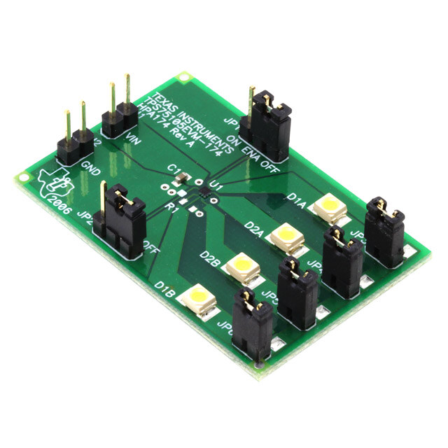
| 描述 | EVAL MODULE FOR TPS75105-174LED 照明开发工具 LDO REGULATOR |
| 产品分类 | |
| 品牌 | Texas Instruments |
| 产品手册 | |
| 产品图片 |
|
| rohs | 否库存产品核实请求 / 库存产品核实请求 |
| 产品系列 | LED 照明开发工具,Texas Instruments TPS75105EVM-174- |
| 数据手册 | 点击此处下载产品Datasheethttp://www.ti.com/lit/pdf/slvu182 |
| 产品型号 | TPS75105EVM-174 |
| 产品 | Evaluation Modules |
| 产品种类 | LED 照明开发工具 |
| 使用的IC/零件 | TPS75105 |
| 其它名称 | 296-31291 |
| 制造商产品页 | http://www.ti.com/general/docs/suppproductinfo.tsp?distId=10&orderablePartNumber=TPS75105EVM-174 |
| 商标 | Texas Instruments |
| 工作电源电压 | 2.7 V to 5.5 V |
| 工厂包装数量 | 1 |
| 所含物品 | 板 |
| 标准包装 | 1 |
| 特性 | 可调光 |
| 用于 | TPS75100/75105 |
| 电压-输入 | 2.7 V ~ 5.5 V |
| 电压-输出 | - |
| 电流-输出/通道 | 5mA |
| 相关产品 | /product-detail/zh/TPS75105YFFR/296-20790-2-ND/1204559/product-detail/zh/TPS75105YFFR/296-20790-1-ND/1204652/product-detail/zh/TPS75105YFFT/TPS75105YFFT-ND/1673031 |
| 输出和类型 | 4,非隔离 |




- 商务部:美国ITC正式对集成电路等产品启动337调查
- 曝三星4nm工艺存在良率问题 高通将骁龙8 Gen1或转产台积电
- 太阳诱电将投资9.5亿元在常州建新厂生产MLCC 预计2023年完工
- 英特尔发布欧洲新工厂建设计划 深化IDM 2.0 战略
- 台积电先进制程称霸业界 有大客户加持明年业绩稳了
- 达到5530亿美元!SIA预计今年全球半导体销售额将创下新高
- 英特尔拟将自动驾驶子公司Mobileye上市 估值或超500亿美元
- 三星加码芯片和SET,合并消费电子和移动部门,撤换高东真等 CEO
- 三星电子宣布重大人事变动 还合并消费电子和移动部门
- 海关总署:前11个月进口集成电路产品价值2.52万亿元 增长14.8%



PDF Datasheet 数据手册内容提取
User's Guide SLVU182–September2006 TPS75105EVM This user’s guide describes the characteristics, operation, and use of the TPS75105EVM-174 evaluation module (EVM). The EVM demonstrates the Texas Instruments TPS75105 low-dropout, two-bank LED driver with PWM brightness control. The document Includes setup instructions, a schematic diagram, a bill of materials, and PCBlayoutdrawingsfortheEVM. Contents 1 Introduction.......................................................................................... 1 2 Setup................................................................................................. 1 3 BoardLayout........................................................................................ 3 4 SchematicandBillofMaterials................................................................... 6 ListofFigures 1 AssemblyLayer..................................................................................... 4 2 TopLayerRouting.................................................................................. 5 3 BottomLayerRouting.............................................................................. 6 4 TPS75105EVM-174Schematic................................................................... 7 ListofTables 1 TPS75105EVM-174BillofMaterials............................................................. 7 1 Introduction TheTexasInstrumentsTPS75105EVM-174evaluationmodule(EVM)helpsdesignersevaluatethe operationandperformanceoftheTPS75105low-dropoutlinearregulator(LDO),two-bankLEDdriverwith PWMdimming.TheTPS75100containsfour,current-regulated,LEDdriveroutputsandoperatesfroma 2.7-Vto5.5-Vinputsupply.TheICdrivestheanodesoftwobanksoftwoLEDs.Eachbankisenabled independentlyandcanbedimmedusingaPWMsignaltotheENpin.TheLEDcurrentisprogrammed usingaresistorfromISETtoGND.TheEVMhasjumpersforbothENinputpinsforeasyevaluation.The LDOtopologyandthe9-ballchipscalepackageprovideasmall-footprintsolutionforbattery-poweredLED driverapplications. 2 Setup ThissectiondescribesthejumpersandconnectorsontheEVMaswellashowtoproperlyconnect,set up,andusetheTPS75105EVM-174. 2.1 Input/Output Connector Descriptions 2.1.1 J1–VIN Thisisthepositiveinputvoltageconnectiontotheconverter.TheEVMoperatesfromanysupplyvoltage between2.7Vand5.5V.Theleadstotheinputsupplyshouldbetwistedandkeptasshortaspossibleto minimizeEMItransmissionandinputvoltagedroop. SLVU182–September2006 TPS75105EVM 1 SubmitDocumentationFeedback
www.ti.com Setup 2.1.2 J2–GND Thisistheinputreturnconnectionfortheinputpowersupply. 2.1.3 JP1–Bank-AEnable JP1isusedtoenablethebank-ALEDs.PlaceashortingbarintheONpositiontoturnonthebank-A LEDs.Whenthebank-ALEDsareenabled,theLEDcurrentthroughLEDsD1AandD2Aisregulatedto thevalueprogrammedatISET(5mA).PlaceashortingbarintheOFFpositiontoturnoffthebank-A LEDs. 2.1.4 JP2–Bank-BEnable JP2isusedtoenablethebank-BLEDs.PlaceashortingbarintheONpositiontoturnonthebank-B LEDs.Whenthebank-BLEDsareenabled,theLEDcurrentthroughLEDsD1BandD2Bisregulatedto thevalueprogrammedatISET(5mA).PlaceashortingbarintheOFFpositiontoturnoffthebank-B LEDs. 2.1.5 JP3–LEDD1ACathodeConnection JP3isusedtomeasurethecurrentthroughLEDD1A.PlaceacurrentmeterbetweenthepinsofJP3to measurethecurrent.Alternatively,aresistorcanbeconnectedbetweenthepinsofJP3inorderto measurethecurrentasavoltage.PlaceashortingbaracrossthepinsofJP3ifcurrentmeasurementis notrequired.PCBpadsareprovidedtoinstallacurrent-senseresistoracrossthisjumper. 2.1.6 JP4–LEDD2ACathodeConnection JP4isusedtomeasurethecurrentthroughLEDD2A.PlaceacurrentmeterbetweenthepinsofJP4to measurethecurrent.Alternatively,aresistorcanbeconnectedbetweenthepinsofJP4inorderto measurethecurrentasavoltage.PlaceashortingbaracrossthepinsofJP4ifcurrentmeasurementis notrequired.PCBpadsareprovidedtoinstallacurrent-senseresistoracrossthisjumper. 2.1.7 JP5–LEDD2BCathodeConnection JP5isusedtomeasurethecurrentthroughLEDD2B.PlaceacurrentmeterbetweenthepinsofJP5to measurethecurrent.Alternatively,aresistorcanbeconnectedbetweenthepinsofJP5inorderto measurethecurrentasavoltage.PlaceashortingbaracrossthepinsofJP5ifcurrentmeasurementis notrequired.PCBpadsareprovidedtoinstallacurrent-senseresistoracrossthisjumper. 2.1.8 JP6–LEDD1BCathodeConnection JP6isusedtomeasurethecurrentthroughLEDD1B.PlaceacurrentmeterbetweenthepinsofJP6to measurethecurrent.Alternatively,aresistorcanbeconnectedbetweenthepinsofJP6inorderto measurethecurrentasavoltage.PlaceashortingbaracrossthepinsofJP6ifcurrentmeasurementis notrequired.PCBpadsareprovidedtoinstallacurrent-senseresistoracrossthisjumper. 2.2 Setup 2.2.1 EVMFactoryConfiguration TheEVMisconfiguredtoprovidethefollowingnominaloperatingconditions: Inputvoltage:2.5Vto5.5V LEDcurrent:5mA 2 TPS75105EVM SLVU182–September2006 SubmitDocumentationFeedback
www.ti.com BoardLayout 2.2.2 ChangingLEDCurrent R1ontheEVMisusedtochangethecurrent.TheEVMisprovidedwithnoresistorinstalledonR1.This programsthedefaultLEDcurrentof5mA.InordertoprogramadifferentLEDcurrent,placea1% resistoratR1thatcorrespondstothefollowingequation: R1=(1.22V/I )· 420 LED NotethatI istheLEDcurrentthrougheachLED. LED 2.2.3 UsingPWMDimming AneasydimmingsolutionisimplementedbyconnectingaPWMsignaltoENAorENBtodimthe respectivebankofLEDs.ThePWMsignalmaybeupto1kHz.ThescaleoftheLEDcurrentcorresponds directlytothedutycycleofthesignal.Forexample,a50%dutycycleprovides50%oftheprogrammed LEDcurrent.Thetwobanksmaybeindependentlydimmed. 2.2.4 Operation 1. ConfigureJP1toenableordisablethebank-ALEDsasdesired. 2. ConfigureJP2toenableordisablethebank-BLEDsasdesired. 3. ConfigureJP3–JP6tomeasureLEDcurrent. 4. ConnecttheinputvoltagereturntoJ2. 5. ConnectthepositiveinputvoltagetoJ1. 6. Turnoninputvoltage. 7. TheLEDsthatwereenabledbyJP1andJP2areon. 3 Board Layout ThissectionprovidestheTPS75105EVM-174boardlayoutandillustrations. SLVU182–September2006 TPS75105EVM 3 SubmitDocumentationFeedback
www.ti.com BoardLayout 3.1 Layout Figure1,Figure2,andFigure3showtheboardlayoutfortheTPS75105EVM-174PWB. Figure1.AssemblyLayer 4 TPS75105EVM SLVU182–September2006 SubmitDocumentationFeedback
www.ti.com BoardLayout Figure2.TopLayerRouting SLVU182–September2006 TPS75105EVM 5 SubmitDocumentationFeedback
www.ti.com SchematicandBillofMaterials Figure3.BottomLayerRouting 4 Schematic and Bill of Materials ThissectionprovidestheTPS75105EVM-174schematicandbillofmaterials. 6 TPS75105EVM SLVU182–September2006 SubmitDocumentationFeedback
www.ti.com SchematicandBillofMaterials 4.1 Schematic Figure4.TPS75105EVM-174Schematic 4.2 Bill of Materials Table1.TPS75105EVM-174BillofMaterials Count RefDes Value Description Size PartNumber MFR 1 C1 1.0m F Capacitor,Ceramic,16V,X5R,10% 0603 C1608X5R1C105K TDK 4 D1A,D1B, Diode,LED,White,30mA 1210 SML-LX2832UWC- Lumex D2A,D2B TR 2 J1,J2 Header,2pin,100milspacing,(36-pinstrip) 0.100· 2 PTC36SAAN Sullins 2 JP1,JP2 Header,3pin,100milspacing,(36-pinstrip) 0.100· 3 PTC36SAAN Sullins 4 JP3–JP6 Header,2pin,100milspacing,(36-pinstrip) 0.100· 2 PTC36SAAN Sullins 0 R1 Open Resistor,Cip,1/16W,1% 0603 1 U1 IC,LDO,TwoBankLEDDriver1/PWM WCSP-0 TPS75105YFF TI BrightnessControl 1 — PCB,1.8In· 1.2In· 0.062In HPA174 Any 6 — Shunt,100mil,Black 0.100 929950-00 3M 4.3 Related Documentation From Texas Instruments TPS7510x,LowDropout,Two-BankLEDDriverwithPWMBrightnessControldatasheet(SBVS080) 4.4 If You Need Assistance ContactyourlocalTIsalesrepresentative. SLVU182–September2006 TPS75105EVM 7 SubmitDocumentationFeedback
EVALUATIONBOARD/KITIMPORTANTNOTICE TexasInstruments(TI)providestheenclosedproduct(s)underthefollowingconditions: Thisevaluationboard/kitisintendedforuseforENGINEERINGDEVELOPMENT,DEMONSTRATION,OREVALUATION PURPOSESONLYandisnotconsideredbyTItobeafinishedend-productfitforgeneralconsumeruse.Personshandlingthe product(s)musthaveelectronicstrainingandobservegoodengineeringpracticestandards.Assuch,thegoodsbeingprovidedare notintendedtobecompleteintermsofrequireddesign-,marketing-,and/ormanufacturing-relatedprotectiveconsiderations, includingproductsafetyandenvironmentalmeasurestypicallyfoundinendproductsthatincorporatesuchsemiconductor componentsorcircuitboards.Thisevaluationboard/kitdoesnotfallwithinthescopeoftheEuropeanUniondirectivesregarding electromagneticcompatibility,restrictedsubstances(RoHS),recycling(WEEE),FCC,CEorUL,andthereforemaynotmeetthe technicalrequirementsofthesedirectivesorotherrelateddirectives. Shouldthisevaluationboard/kitnotmeetthespecificationsindicatedintheUser’sGuide,theboard/kitmaybereturnedwithin30 daysfromthedateofdeliveryforafullrefund.THEFOREGOINGWARRANTYISTHEEXCLUSIVEWARRANTYMADEBY SELLERTOBUYERANDISINLIEUOFALLOTHERWARRANTIES,EXPRESSED,IMPLIED,ORSTATUTORY,INCLUDING ANYWARRANTYOFMERCHANTABILITYORFITNESSFORANYPARTICULARPURPOSE. Theuserassumesallresponsibilityandliabilityforproperandsafehandlingofthegoods.Further,theuserindemnifiesTIfromall claimsarisingfromthehandlingoruseofthegoods.Duetotheopenconstructionoftheproduct,itistheuser’sresponsibilityto takeanyandallappropriateprecautionswithregardtoelectrostaticdischarge. EXCEPTTOTHEEXTENTOFTHEINDEMNITYSETFORTHABOVE,NEITHERPARTYSHALLBELIABLETOTHEOTHER FORANYINDIRECT,SPECIAL,INCIDENTAL,ORCONSEQUENTIALDAMAGES. TIcurrentlydealswithavarietyofcustomersforproducts,andthereforeourarrangementwiththeuserisnotexclusive. TIassumesnoliabilityforapplicationsassistance,customerproductdesign,softwareperformance,orinfringementof patentsorservicesdescribedherein. PleasereadtheUser’sGuideand,specifically,theWarningsandRestrictionsnoticeintheUser’sGuidepriortohandlingthe product.Thisnoticecontainsimportantsafetyinformationabouttemperaturesandvoltages.ForadditionalinformationonTI’s environmentaland/orsafetyprograms,pleasecontacttheTIapplicationengineerorvisitwww.ti.com/esh. NolicenseisgrantedunderanypatentrightorotherintellectualpropertyrightofTIcoveringorrelatingtoanymachine,process,or combinationinwhichsuchTIproductsorservicesmightbeorareused. FCCWarning Thisevaluationboard/kitisintendedforuseforENGINEERINGDEVELOPMENT,DEMONSTRATION,OREVALUATION PURPOSESONLYandisnotconsideredbyTItobeafinishedend-productfitforgeneralconsumeruse.Itgenerates,uses,and canradiateradiofrequencyenergyandhasnotbeentestedforcompliancewiththelimitsofcomputingdevicespursuanttopart15 ofFCCrules,whicharedesignedtoprovidereasonableprotectionagainstradiofrequencyinterference.Operationofthis equipmentinotherenvironmentsmaycauseinterferencewithradiocommunications,inwhichcasetheuserathisownexpense willberequiredtotakewhatevermeasuresmayberequiredtocorrectthisinterference. EVMWARNINGSANDRESTRICTIONS ItisimportanttooperatethisEVMwithintheinputvoltagerangeof2.7Vto5.5V. Exceedingthespecifiedinputrangemaycauseunexpectedoperationand/orirreversibledamagetotheEVM.Ifthereare questionsconcerningtheinputrange,pleasecontactaTIfieldrepresentativepriortoconnectingtheinputpower. Applyingloadsoutsideofthespecifiedoutputrangemayresultinunintendedoperationand/orpossiblepermanentdamagetothe EVM.PleaseconsulttheEVMUser'sGuidepriortoconnectinganyloadtotheEVMoutput.Ifthereisuncertaintyastotheload specification,pleasecontactaTIfieldrepresentative. Duringnormaloperation,somecircuitcomponentsmayhavecasetemperaturesgreaterthan85(cid:176) C.TheEVMisdesignedto operateproperlywithcertaincomponentsabove60(cid:176) Caslongastheinputandoutputrangesaremaintained.Thesecomponents includebutarenotlimitedtolinearregulators,switchingtransistors,passtransistors,andcurrentsenseresistors.Thesetypesof devicescanbeidentifiedusingtheEVMschematiclocatedintheEVMUser'sGuide.Whenplacingmeasurementprobesnear thesedevicesduringoperation,pleasebeawarethatthesedevicesmaybeverywarmtothetouch. MailingAddress:TexasInstruments,PostOfficeBox655303,Dallas,Texas75265 Copyright©2006,TexasInstrumentsIncorporated
IMPORTANTNOTICE TexasInstrumentsIncorporatedanditssubsidiaries(TI)reservetherighttomakecorrections,modifications,enhancements, improvements,andotherchangestoitsproductsandservicesatanytimeandtodiscontinueanyproductorservicewithoutnotice. Customersshouldobtainthelatestrelevantinformationbeforeplacingordersandshouldverifythatsuchinformationiscurrentand complete.AllproductsaresoldsubjecttoTI’stermsandconditionsofsalesuppliedatthetimeoforderacknowledgment. TIwarrantsperformanceofitshardwareproductstothespecificationsapplicableatthetimeofsaleinaccordancewithTI’s standardwarranty.TestingandotherqualitycontroltechniquesareusedtotheextentTIdeemsnecessarytosupportthis warranty.Exceptwheremandatedbygovernmentrequirements,testingofallparametersofeachproductisnotnecessarily performed. TIassumesnoliabilityforapplicationsassistanceorcustomerproductdesign.Customersareresponsiblefortheirproductsand applicationsusingTIcomponents.Tominimizetherisksassociatedwithcustomerproductsandapplications,customersshould provideadequatedesignandoperatingsafeguards. TIdoesnotwarrantorrepresentthatanylicense,eitherexpressorimplied,isgrantedunderanyTIpatentright,copyright,mask workright,orotherTIintellectualpropertyrightrelatingtoanycombination,machine,orprocessinwhichTIproductsorservices areused.InformationpublishedbyTIregardingthird-partyproductsorservicesdoesnotconstitutealicensefromTItousesuch productsorservicesorawarrantyorendorsementthereof.Useofsuchinformationmayrequirealicensefromathirdpartyunder thepatentsorotherintellectualpropertyofthethirdparty,oralicensefromTIunderthepatentsorotherintellectualpropertyofTI. ReproductionofinformationinTIdatabooksordatasheetsispermissibleonlyifreproductioniswithoutalterationandis accompaniedbyallassociatedwarranties,conditions,limitations,andnotices.Reproductionofthisinformationwithalterationisan unfairanddeceptivebusinesspractice.TIisnotresponsibleorliableforsuchaltereddocumentation. ResaleofTIproductsorserviceswithstatementsdifferentfromorbeyondtheparametersstatedbyTIforthatproductorservice voidsallexpressandanyimpliedwarrantiesfortheassociatedTIproductorserviceandisanunfairanddeceptivebusiness practice.TIisnotresponsibleorliableforanysuchstatements. TIproductsarenotauthorizedforuseinsafety-criticalapplications(suchaslifesupport)whereafailureoftheTIproductwould reasonablybeexpectedtocauseseverepersonalinjuryordeath,unlessofficersofthepartieshaveexecutedanagreement specificallygoverningsuchuse.Buyersrepresentthattheyhaveallnecessaryexpertiseinthesafetyandregulatoryramifications oftheirapplications,andacknowledgeandagreethattheyaresolelyresponsibleforalllegal,regulatoryandsafety-related requirementsconcerningtheirproductsandanyuseofTIproductsinsuchsafety-criticalapplications,notwithstandingany applications-relatedinformationorsupportthatmaybeprovidedbyTI.Further,BuyersmustfullyindemnifyTIandits representativesagainstanydamagesarisingoutoftheuseofTIproductsinsuchsafety-criticalapplications. TIproductsareneitherdesignednorintendedforuseinmilitary/aerospaceapplicationsorenvironmentsunlesstheTIproductsare specificallydesignatedbyTIasmilitary-gradeor"enhancedplastic."OnlyproductsdesignatedbyTIasmilitary-grademeetmilitary specifications.BuyersacknowledgeandagreethatanysuchuseofTIproductswhichTIhasnotdesignatedasmilitary-gradeis solelyattheBuyer'srisk,andthattheyaresolelyresponsibleforcompliancewithalllegalandregulatoryrequirementsin connectionwithsuchuse. TIproductsareneitherdesignednorintendedforuseinautomotiveapplicationsorenvironmentsunlessthespecificTIproducts aredesignatedbyTIascompliantwithISO/TS16949requirements.Buyersacknowledgeandagreethat,iftheyuseany non-designatedproductsinautomotiveapplications,TIwillnotberesponsibleforanyfailuretomeetsuchrequirements. FollowingareURLswhereyoucanobtaininformationonotherTexasInstrumentsproductsandapplicationsolutions: Products Applications Amplifiers amplifier.ti.com Audio www.ti.com/audio DataConverters dataconverter.ti.com Automotive www.ti.com/automotive DSP dsp.ti.com Broadband www.ti.com/broadband Interface interface.ti.com DigitalControl www.ti.com/digitalcontrol Logic logic.ti.com Military www.ti.com/military PowerMgmt power.ti.com OpticalNetworking www.ti.com/opticalnetwork Microcontrollers microcontroller.ti.com Security www.ti.com/security RFID www.ti-rfid.com Telephony www.ti.com/telephony LowPower www.ti.com/lpw Video&Imaging www.ti.com/video Wireless Wireless www.ti.com/wireless MailingAddress:TexasInstruments,PostOfficeBox655303,Dallas,Texas75265 Copyright©2007,TexasInstrumentsIncorporated
 Datasheet下载

