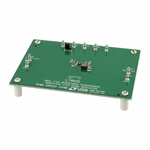
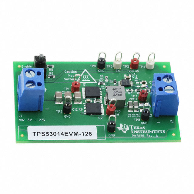
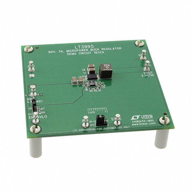
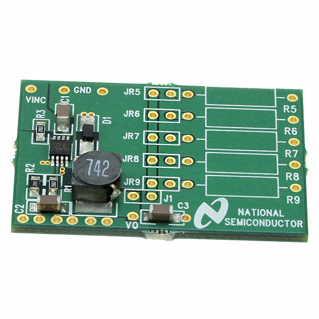
ICGOO在线商城 > 开发板,套件,编程器 > 评估板 - DC/DC 与 AC/DC(离线)SMPS > TPS75003EVM-092
- 型号: TPS75003EVM-092
- 制造商: Texas Instruments
- 库位|库存: xxxx|xxxx
- 要求:
| 数量阶梯 | 香港交货 | 国内含税 |
| +xxxx | $xxxx | ¥xxxx |
查看当月历史价格
查看今年历史价格
TPS75003EVM-092产品简介:
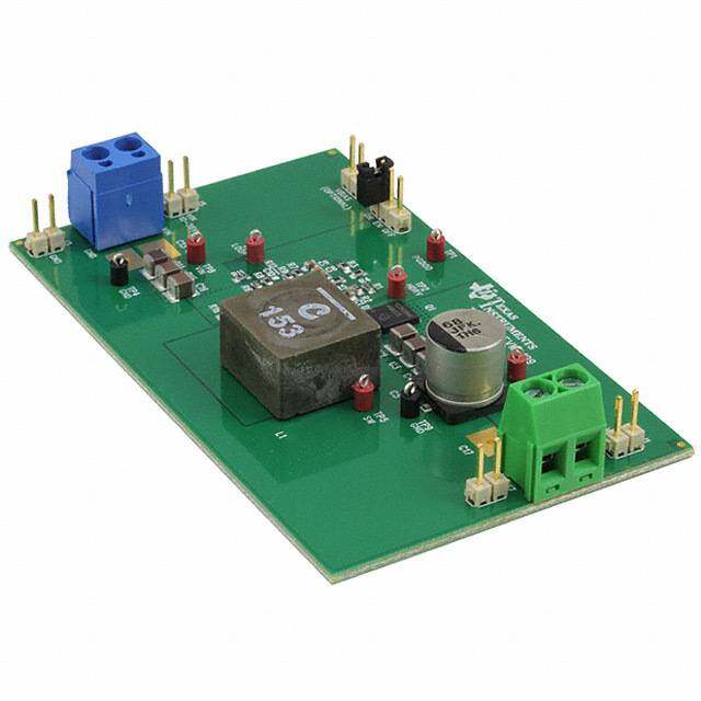
ICGOO电子元器件商城为您提供TPS75003EVM-092由Texas Instruments设计生产,在icgoo商城现货销售,并且可以通过原厂、代理商等渠道进行代购。 TPS75003EVM-092价格参考¥423.69-¥423.69。Texas InstrumentsTPS75003EVM-092封装/规格:评估板 - DC/DC 与 AC/DC(离线)SMPS, TPS75003 - DC/DC, Step Down with LDO 3, Non-Isolated Outputs Evaluation Board。您可以下载TPS75003EVM-092参考资料、Datasheet数据手册功能说明书,资料中有TPS75003EVM-092 详细功能的应用电路图电压和使用方法及教程。
| 参数 | 数值 |
| 产品目录 | 编程器,开发系统半导体 |
| 描述 | EVALUATION MODULE FOR TPS75003电源管理IC开发工具 TPS75003-092 Eval Mod |
| 产品分类 | |
| 品牌 | Texas Instruments |
| 产品手册 | |
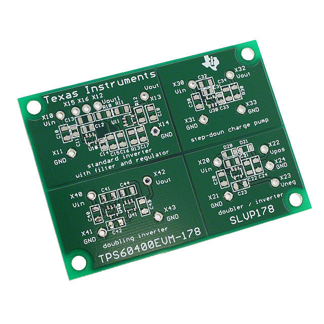
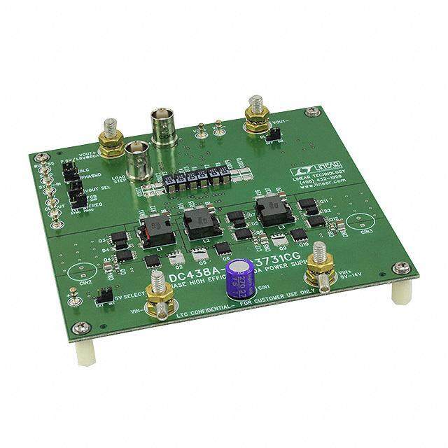
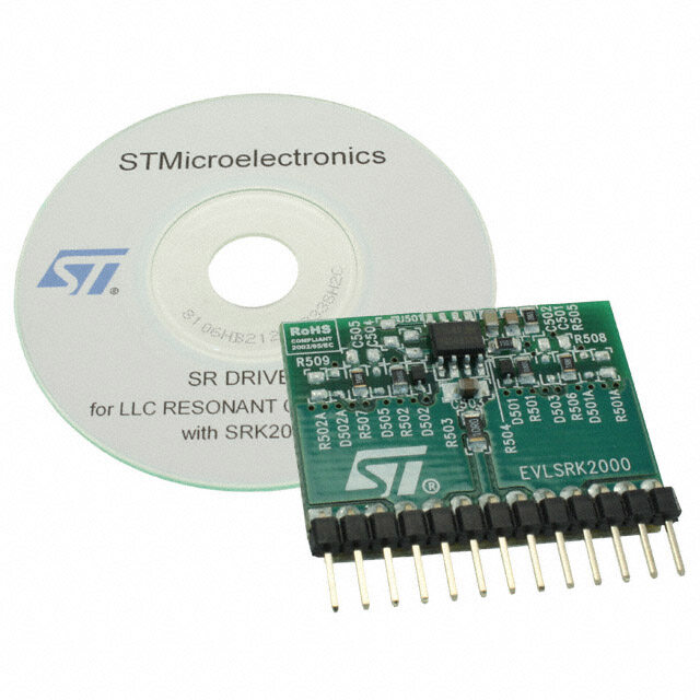
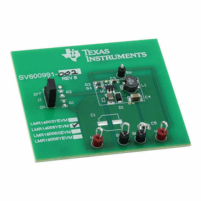
| 产品图片 |
|
| rohs | 否含铅 / 不符合限制有害物质指令(RoHS)规范要求 |
| 产品系列 | 电源管理IC开发工具,Texas Instruments TPS75003EVM-092- |
| 数据手册 | 点击此处下载产品Datasheethttp://www.ti.com/lit/pdf/slvu116 |
| 产品型号 | TPS75003EVM-092 |
| 主要用途 | DC/DC,LDO 步降 |
| 产品 | Evaluation Boards |
| 产品目录页面 | |
| 产品种类 | 电源管理IC开发工具 |
| 使用的IC/零件 | TPS75003 |
| 其它名称 | 296-21171 |
| 制造商产品页 | http://www.ti.com/general/docs/suppproductinfo.tsp?distId=10&orderablePartNumber=TPS75003EVM-092 |
| 功率-输出 | - |
| 参考设计库 | http://www.digikey.com/rdl/4294959904/4294959903/230 |
| 商标 | Texas Instruments |
| 尺寸 | 61 mm x 55.9 mm |
| 工具用于评估 | TPS75003 |
| 工厂包装数量 | 1 |
| 所含物品 | 板 |
| 板类型 | 完全填充 |
| 标准包装 | 1 |
| 电压-输入 | 2.2 V ~ 6.5 V |
| 电压-输出 | 1.22V,2.5V,3.3V |
| 电流-输出 | 2A,2A,300mA |
| 相关产品 | /product-detail/zh/TPS75003RHLT/296-19438-2-ND/725741/product-detail/zh/TPS75003RHLR/296-17835-2-ND/735836/product-detail/zh/TPS75003RHLR/296-17835-1-ND/735837/product-detail/zh/TPS75003RHLT/296-19438-1-ND/966899/product-detail/zh/TPS75003MRHLREP/296-22499-2-ND/1666657/product-detail/zh/TPS75003QRHLREP/296-22500-2-ND/1666658/product-detail/zh/TPS75003MRHLREP/296-22499-1-ND/1667068/product-detail/zh/TPS75003QRHLREP/296-22500-1-ND/1667069/product-detail/zh/TPS75003RHLRG4/TPS75003RHLRG4-ND/1673025/product-detail/zh/TPS75003RHLTG4/TPS75003RHLTG4-ND/1673026/product-detail/zh/TPS75003RHLR/296-17835-6-ND/1763349/product-detail/zh/TPS75003MRHLREP/296-22499-6-ND/1944943/product-detail/zh/TPS75003QRHLREP/296-22500-6-ND/1944944/product-detail/zh/TPS75003RHLT/296-19438-6-ND/1946456 |
| 稳压器拓扑 | 降压 |
| 类型 | PMIC Solutions |
| 输入电压 | 2.2 V to 6.5 V |
| 输出和类型 | 3,非隔离 |
| 输出电压 | 3.3 V |
| 频率-开关 | - |




- 商务部:美国ITC正式对集成电路等产品启动337调查
- 曝三星4nm工艺存在良率问题 高通将骁龙8 Gen1或转产台积电
- 太阳诱电将投资9.5亿元在常州建新厂生产MLCC 预计2023年完工
- 英特尔发布欧洲新工厂建设计划 深化IDM 2.0 战略
- 台积电先进制程称霸业界 有大客户加持明年业绩稳了
- 达到5530亿美元!SIA预计今年全球半导体销售额将创下新高
- 英特尔拟将自动驾驶子公司Mobileye上市 估值或超500亿美元
- 三星加码芯片和SET,合并消费电子和移动部门,撤换高东真等 CEO
- 三星电子宣布重大人事变动 还合并消费电子和移动部门
- 海关总署:前11个月进口集成电路产品价值2.52万亿元 增长14.8%
PDF Datasheet 数据手册内容提取
User's Guide SLVU116B–December2004–RevisedSeptember2011 TPS75003EVM User's Guide Contents 1 Introduction .................................................................................................................. 1 2 PerformanceSpecificationSummary..................................................................................... 2 3 Modifications ................................................................................................................. 2 4 BoardLayout ................................................................................................................ 5 5 Schematic .................................................................................................................. 11 6 BillofMaterials............................................................................................................. 12 ListofFigures 1 EfficiencyWithV =5V,V =1.2V,V =3.3V ................................................................. 3 IN OUT1 OUT2 2 NormalizedLoadRegulationWithV =5V,V =1.2V,V =3.3V .......................................... 4 IN OUT1 OUT2 3 OutputRipplewhenV =5V,V =1.2V,I =2A............................................................... 4 IN OUT1 OUT1 4 OutputRippleWhenV =5V,V =3.3V,I =2A.............................................................. 5 IN OUT2 OUT2 5 SoftStartWithV =5.0V................................................................................................. 5 IN 6 TopLayer.................................................................................................................... 6 7 BottomLayer................................................................................................................ 7 8 TopAssembly............................................................................................................... 8 9 Layer2....................................................................................................................... 9 10 Layer3...................................................................................................................... 10 11 TPS75003EVMSchematic............................................................................................... 11 ListofTables 1 TypicalPerformanceSpecificationSummary........................................................................... 2 2 TPS75003EVMBillofMaterials......................................................................................... 12 1 Introduction TheTexasInstrumentsTPS75003EVMevaluationmodule(EVM)helpsdesignersevaluatetheoperation andperformanceoftheTPS75003multi-channelpowerIC.Thisdevicehastwobuckcontrollersandalow dropoutlinearregulator.Thedevicewilloperateatinputvoltagesbetween2.2Vand6.5V.Thebuck controllerscanprovideoutputvoltagesbetween1.22Vandtheinputvoltageandoutputcurrentsupto3 A.ThisEVMisspecificallydesignedandoptimizedtooperatefroma5Vinputwithoutputcurrentsupto 2AforV =1.2VtypicalandV =3.3Vtypical.Inaddition,theEVMisjumperconfigurablesothat OUT1 OUT2 eachoutputcanbeindependentlyenabledortheoutputscanbesequencedinthefollowingorder:V , OUT3 V thenV . OUT2 OUT1 SLVU116B–December2004–RevisedSeptember2011 TPS75003EVMUser'sGuide 1 SubmitDocumentationFeedback Copyright©2004–2011,TexasInstrumentsIncorporated
PerformanceSpecificationSummary www.ti.com 2 Performance Specification Summary Table1providesasummaryoftheTPS75003EVMperformancespecifications.Allspecificationsaregiven foranambienttemperatureof25°C. Table1.TypicalPerformanceSpecificationSummary VOLTAGERANGE CURRENTRANGE CONDITION (V) (mA) MIN TYP MAX MIN TYP MAX V BuckController V =5V 1.18 1.22 1.26 0 2000 OUT1 I V BuckController V =5V 3.15 3.30 3.43 0 2000 OUT2 I V LinearRegulator V =5V 2.41 2.50 2.65 0 300 OUT3 I 3 Modifications Passivecomponentswith603orlargerfootprintswereusedtoallowforusercustomization. Additionally,asecondsoftstartcapacitorwasaddedforbuckcontrollerbutnotpopulatedtoallowthe softstarttimingtobeeasilymodified. InputcapacitorC1wasincludedtominimizeinductivedroopduetolongleadsfromabenchpower supply.Acapacitorofsimilarsizemayormaynotbeneededinarealapplicationdependingonthe proximitytotheinputpowersupply. Ifalloftheoutputvoltagesareequaltoorgreaterthantheminimum1.4VthresholdforEN1andEN2, thentheoutputscanbesequencedinanyorderbysimplymodifyingtheV toENxconnections.If OUTx oneofthebuckoutputvoltagesisbetween1.2Vand1.4V,thenonlyEN3withitsminimum1.1V thresholdcanbeenabledbythisoutputvoltage.Forexample,ifV =1.2V,V =3.3VandV = OUT1 OUT2 OUT3 2.5V,thefollowingadditionalsequencingoptionsareavailablebymodifyingtheEVM'sV toENx OUTx connections:V =1.2V,V =2.5VthenV =3.3VorV =3.3V,V =2.5VthenV = OUT1 OUT3 OUT2 OUT2 OUT3 OUT1 1.2V.AnexternalSVS,liketheTPS3808,monitoringthe1.2Vto1.4VrailandwithitsRESEToutput tiedtoENxcanbeusedtoprovidetheremainingsequencingoptions. 3.1 Input/Output Connector Descriptions ThischapterdescribesthejumpersandconnectorsontheEVMaswellashowtoproperlyconnect,setup, andusetheTPS75003EVM. J1–VIN— Thisisthepositiveconnectiontotheinputpowersupply.Theleadstotheinputsupplyshould betwistedandkeptasshortaspossibletominimizeEMItransmission. J2–GND— Thisisthereturnconnectionfortheinputpowersupply. J3–VOUT1— ThisisthepositiveconnectionfortheV output.Connectthispintothepositiveinputof OUT1 theV load. OUT1 J4–GND— ThisisthenegativeconnectionfortheV output.Connectthispintothenegativeinputof OUT1 theV load. OUT1 J5–VOUT2— ThisisthepositiveconnectionfortheV output.Connectthispintothepositiveinputof OUT2 theV load. OUT2 J6–GND— ThisisthenegativeconnectionfortheV output.Connectthispintothenegativeinputof OUT2 theV load. OUT2 J7–VOUT3— ThisisthepositiveconnectionfortheV output.Connectthispintothepositiveinputof OUT3 theV load. OUT3 J8–GND— ThisisthenegativeconnectionfortheV output.Connectthispintothenegativeinputof OUT3 theV load. OUT3 2 TPS75003EVMUser'sGuide SLVU116B–December2004–RevisedSeptember2011 SubmitDocumentationFeedback Copyright©2004–2011,TexasInstrumentsIncorporated
www.ti.com Modifications JP1– ENVO1— ThisjumperenablesanddisablesV .Withthejumperremoved(DEFAULT),EN1is OUT1 pulledlowbyanexternalpulldownresistorandV isdisabled.WiththejumpertiedtoV ,EN1is OUT1 IN pulledhightoV andV isenabled.WiththejumpertiedtoAFTERVO2,EN1istiedtoV so IN OUT1 OUT2 thatV willnotbeenableduntilafterV isenabled. OUT1 OUT2 JP2– ENVO2— ThisjumperenablesanddisablesV .Withthejumperremoved(DEFAULT),EN2is OUT2 pulledlowbyanexternalpulldownresistorandV isdisabled.Withthejumperinstalled,EN2is OUT2 pulledhightoV andV isenabled.WiththejumpertiedtoAFTERVO3,EN3istiedtoV so IN OUT2 OUT3 thatV willnotbeenableduntilafterV isenabled. OUT2 OUT3 JP3– ENVO3— ThisjumperenablesanddisablesV .Withthejumperremoved(DEFAULT),EN3is OUT3 pulledlowbyanexternalpulldownresistorandV isdisabled.WiththejumpertiedtoV ,EN3is OUT3 IN pulledhightoV andV isenabled. IN OUT3 3.2 Setup ConnectaninputsupplybetweenJ1andJ2.Thevoltagerangeonthissupplyshouldstaybetween2.2V and6.5V.Connectaloadnottoexceed2AforthebuckcontrollersbetweenJ3andJ4forV and OUT1 betweenJ5andJ6forV .Connectaloadnottoexceed300mAforthelinearregulatorbetweenJ7 OUT2 andJ8.ConfiguretheJP1,JP2andJP3enablingjumperstothedesiredsetting.Topreventnoisepickup fromdistortingvoltagemeasurementsofanyofthethreeoutputvoltages,keeptheloopcreatedbythe voltageprobetipanditsgroundconnectionassmallaspossibleandasfarawayaspossiblefromthe inductorsontheboard. 3.3 Test Results 100 VIN = 5 V VOUT2 = 3.3 V VOUT1 = 1.2 V 80 % − y c n e 60 ci Effi 40 20 0 500 1000 1500 2000 IO − Output Current − mA A EfficiencymaybeimprovedordegradedbyusingdifferentFETsand/orinductors. Figure1.EfficiencyWithV =5V,V =1.2V,V =3.3V IN OUT1 OUT2 SLVU116B–December2004–RevisedSeptember2011 TPS75003EVMUser'sGuide 3 SubmitDocumentationFeedback Copyright©2004–2011,TexasInstrumentsIncorporated
Modifications www.ti.com 1.03 VIN = 5 V n 1.02 o ulati VOUT1 = 1.2 V eg 1.01 R ad VOUT2 = 3.3 V o L 1 d e z ali 0.99 m r o N 0.98 0.97 0 500 1000 1500 2000 IO − Output Current − mA Figure2.NormalizedLoadRegulationWithV =5V,V =1.2V,V =3.3V IN OUT1 OUT2 80 − V 60 e g a olt 40 V put 20 ut O d 0 e pl u o c −20 − C A − C) −40 A O( V −60 −80 0 5 10 15 20 25 30 35 40 45 50 t − Time − (cid:1)s Figure3.OutputRipplewhenV =5V,V =1.2V,I =2A IN OUT1 OUT1 4 TPS75003EVMUser'sGuide SLVU116B–December2004–RevisedSeptember2011 SubmitDocumentationFeedback Copyright©2004–2011,TexasInstrumentsIncorporated
www.ti.com BoardLayout 80 V − 60 e g a olt 40 V ut p 20 ut O d e 0 pl u o c −20 − C A − C) −40 A O( V −60 −80 0 5 10 15 20 25 30 35 40 45 50 t − Time − (cid:1)s Figure4.OutputRippleWhenV =5V,V =3.3V,I =2A IN OUT2 OUT2 OUTPUT VOLTAGE vs TIME 3.5 VOUT2 = 3.3 V 3 V 2.5 − VOUT3 = 2.5 V e g 2 a olt V ut 1.5 p ut O − 1 VOUT1 = 1.2 V O V 0.5 0 IOUT1 = IOUT2 = 2 A −.5 0 5 10 15 20 25 30 35 40 45 50 t − Time − ms Figure5.SoftStartWithV =5.0V IN 4 Board Layout Boardlayoutiscriticalforallswitchmodepowersupplies.Thefollowingfiguresshoweachofthefour layersoftheTPS75003EVMPWB.Thenodeswithhighswitchingfrequenciesandcurrentsareshortand areisolatedfromthenoisesensitivefeedbackcircuitry.Carefulattentionhasbeengiventotheroutingof highfrequencycurrentloops.Thesenseresistorsforthecurrentlimitandsoftstartshouldbeplaced betweentheINxandISxpinsasclosetotheICaspossible.RefertotheTPS75003datasheet(literature numberSBVS052)foradditionallayoutguidelines. SLVU116B–December2004–RevisedSeptember2011 TPS75003EVMUser'sGuide 5 SubmitDocumentationFeedback Copyright©2004–2011,TexasInstrumentsIncorporated
BoardLayout www.ti.com Figure6.TopLayer 6 TPS75003EVMUser'sGuide SLVU116B–December2004–RevisedSeptember2011 SubmitDocumentationFeedback Copyright©2004–2011,TexasInstrumentsIncorporated
www.ti.com BoardLayout Figure7.BottomLayer SLVU116B–December2004–RevisedSeptember2011 TPS75003EVMUser'sGuide 7 SubmitDocumentationFeedback Copyright©2004–2011,TexasInstrumentsIncorporated
BoardLayout www.ti.com Figure8.TopAssembly 8 TPS75003EVMUser'sGuide SLVU116B–December2004–RevisedSeptember2011 SubmitDocumentationFeedback Copyright©2004–2011,TexasInstrumentsIncorporated
www.ti.com BoardLayout Figure9.Layer2 SLVU116B–December2004–RevisedSeptember2011 TPS75003EVMUser'sGuide 9 SubmitDocumentationFeedback Copyright©2004–2011,TexasInstrumentsIncorporated
BoardLayout www.ti.com Figure10.Layer3 10 TPS75003EVMUser'sGuide SLVU116B–December2004–RevisedSeptember2011 SubmitDocumentationFeedback Copyright©2004–2011,TexasInstrumentsIncorporated
www.ti.com Schematic 5 Schematic + + + Figure11.TPS75003EVMSchematic SLVU116B–December2004–RevisedSeptember2011 TPS75003EVMUser'sGuide 11 SubmitDocumentationFeedback Copyright©2004–2011,TexasInstrumentsIncorporated
BillofMaterials www.ti.com 6 Bill of Materials Table2.TPS75003EVMBillofMaterials COUNT RefDes DESCRIPTION SIZE MFR PARTNUMBER 3 C1,C12,C13 Capacitor,POSCAP,100-µF,6.3-V,45-mΩ,20% 6032(C) Sanyo 6TPB100MC 1 C10 Capacitor,Ceramic,10-pF,50-V,C0G,5% 603 TDK C1608C0G1H100D 0 C11,C15–C18 Capacitor,Ceramic,xx-µF,xx-V 603 2 C2,C4 Capacitor,Ceramic,0.1-µF,16-V,X7R,10% 603 TDK C1608X7R1C104K 2 C3,C5 Capacitor,Ceramic,1500-pF,50-V,X7R,10% 603 TDK C1608X7R1H152K 1 C6 Capacitor,Ceramic,1.0-µF,6.3-V,X5R,10% 603 TDK C1608X5R0J105K 1 C7 Capacitor,Ceramic,0.01-µF,50-V,X7R,10% 603 TDK C1608X7R1H103K 3 C8,C9,C14 Capacitor,Ceramic,10-µF,10-V,X5R,20% 805 TDK C2012X5R1A106MT 1 D1 Diode,Schottky,1A,20V 457-04 OnSemi MBRM120 1 D2 Diode,Schottky,3.0-A,20V SMC Vishay SS32 8 J1–J8 Header,2-pin,100milspacing,(36-pinstrip) 0.100×2 Sullins PTC36SAAN 1 JP2 Header,2-pin,100milspacing,(36-pinstrip) 0.100×2 Sullins PTC36SAAN 2 JP1,JP3 Header,3-pin,100milspacing,(36-pinstrip) 0.100×3 Sullins PTC36SAAN 1 L1 Inductor,SMT,5.0-µH,2.9-A,24-mΩ 0.264sq Sumida CDRH6D38-5R0 1 L2 Inductor,SMT,15-µH,2.6-A,53-mΩ 0.327×0.327 Sumida CDRH8D43-150 2 Q1,Q2 MOSFET,P-ch,20-V,4.7-A,39-mΩ SOT23 Vishay Si2323DS 3 R1–R3 Resistor,chip,100kΩ,1/16W,1% 603 Std Std 1 R10 Resistor,chip,0-Ω,1/16W,5% 603 Std Std 0 R11 Resistor,chip,xx-Ω,1/16W,1% 603 2 R4,R5 Resistor,chip,0.033-Ω,1/4W,1% 1210 Std Std 2 R6,R8 Resistor,chip,61.9kΩ,1/16W,1% 603 Std Std 1 R7 Resistor,chip,15.4kΩ,1/16W,1% 603 Std Std 1 R9 Resistor,chip,36.5kΩ,1/16W,1% 603 Std Std 1 U1 IC,TripleChannelDC/DCConverter QFN-20 TI TPS75003RHLR 1 — PCB,2.4In×2.2In×0.062In Any HPA092 3 — Shunt,100-mil,black 0.100 3M 929950-00 12 TPS75003EVMUser'sGuide SLVU116B–December2004–RevisedSeptember2011 SubmitDocumentationFeedback Copyright©2004–2011,TexasInstrumentsIncorporated
EvaluationBoard/KitImportantNotice TexasInstruments(TI)providestheenclosedproduct(s)underthefollowingconditions: Thisevaluationboard/kitisintendedforuseforENGINEERINGDEVELOPMENT,DEMONSTRATION,OREVALUATION PURPOSESONLYandisnotconsideredbyTItobeafinishedend-productfitforgeneralconsumeruse.Personshandlingthe product(s)musthaveelectronicstrainingandobservegoodengineeringpracticestandards.Assuch,thegoodsbeingprovidedare notintendedtobecompleteintermsofrequireddesign-,marketing-,and/ormanufacturing-relatedprotectiveconsiderations, includingproductsafetyandenvironmentalmeasurestypicallyfoundinendproductsthatincorporatesuchsemiconductor componentsorcircuitboards.Thisevaluationboard/kitdoesnotfallwithinthescopeoftheEuropeanUniondirectivesregarding electromagneticcompatibility,restrictedsubstances(RoHS),recycling(WEEE),FCC,CEorUL,andthereforemaynotmeetthe technicalrequirementsofthesedirectivesorotherrelateddirectives. Shouldthisevaluationboard/kitnotmeetthespecificationsindicatedintheUser’sGuide,theboard/kitmaybereturnedwithin30 daysfromthedateofdeliveryforafullrefund.THEFOREGOINGWARRANTYISTHEEXCLUSIVEWARRANTYMADEBY SELLERTOBUYERANDISINLIEUOFALLOTHERWARRANTIES,EXPRESSED,IMPLIED,ORSTATUTORY,INCLUDING ANYWARRANTYOFMERCHANTABILITYORFITNESSFORANYPARTICULARPURPOSE. Theuserassumesallresponsibilityandliabilityforproperandsafehandlingofthegoods.Further,theuserindemnifiesTIfromall claimsarisingfromthehandlingoruseofthegoods.Duetotheopenconstructionoftheproduct,itistheuser’sresponsibilityto takeanyandallappropriateprecautionswithregardtoelectrostaticdischarge. EXCEPTTOTHEEXTENTOFTHEINDEMNITYSETFORTHABOVE,NEITHERPARTYSHALLBELIABLETOTHEOTHER FORANYINDIRECT,SPECIAL,INCIDENTAL,ORCONSEQUENTIALDAMAGES. TIcurrentlydealswithavarietyofcustomersforproducts,andthereforeourarrangementwiththeuserisnotexclusive. TIassumesnoliabilityforapplicationsassistance,customerproductdesign,softwareperformance,orinfringementof patentsorservicesdescribedherein. PleasereadtheUser’sGuideand,specifically,theWarningsandRestrictionsnoticeintheUser’sGuidepriortohandlingthe product.Thisnoticecontainsimportantsafetyinformationabouttemperaturesandvoltages.ForadditionalinformationonTI’s environmentaland/orsafetyprograms,pleasecontacttheTIapplicationengineerorvisitwww.ti.com/esh. NolicenseisgrantedunderanypatentrightorotherintellectualpropertyrightofTIcoveringorrelatingtoanymachine,process,or combinationinwhichsuchTIproductsorservicesmightbeorareused. FCCWarning Thisevaluationboard/kitisintendedforuseforENGINEERINGDEVELOPMENT,DEMONSTRATION,OREVALUATION PURPOSESONLYandisnotconsideredbyTItobeafinishedend-productfitforgeneralconsumeruse.Itgenerates,uses,and canradiateradiofrequencyenergyandhasnotbeentestedforcompliancewiththelimitsofcomputingdevicespursuanttopart15 ofFCCrules,whicharedesignedtoprovidereasonableprotectionagainstradiofrequencyinterference.Operationofthis equipmentinotherenvironmentsmaycauseinterferencewithradiocommunications,inwhichcasetheuserathisownexpense willberequiredtotakewhatevermeasuresmayberequiredtocorrectthisinterference. EVMWarningsandRestrictions ItisimportanttooperatethisEVMwithintheinputvoltagerangeof2.2Vto6.5Vandtheoutputvoltagerangeof1Vto5.5V. Exceedingthespecifiedinputrangemaycauseunexpectedoperationand/orirreversibledamagetotheEVM.Ifthereare questionsconcerningtheinputrange,pleasecontactaTIfieldrepresentativepriortoconnectingtheinputpower. Applyingloadsoutsideofthespecifiedoutputrangemayresultinunintendedoperationand/orpossiblepermanentdamagetothe EVM.PleaseconsulttheEVMUser'sGuidepriortoconnectinganyloadtotheEVMoutput.Ifthereisuncertaintyastotheload specification,pleasecontactaTIfieldrepresentative. Duringnormaloperation,somecircuitcomponentsmayhavecasetemperaturesgreaterthan125°C.TheEVMisdesignedto operateproperlywithcertaincomponentsabove85°Caslongastheinputandoutputrangesaremaintained.Thesecomponents includebutarenotlimitedtolinearregulators,switchingtransistors,passtransistors,andcurrentsenseresistors.Thesetypesof devicescanbeidentifiedusingtheEVMschematiclocatedintheEVMUser'sGuide.Whenplacingmeasurementprobesnear thesedevicesduringoperation,pleasebeawarethatthesedevicesmaybeverywarmtothetouch. MailingAddress:TexasInstruments,PostOfficeBox655303,Dallas,Texas75265 Copyright©2011,TexasInstrumentsIncorporated
IMPORTANTNOTICE TexasInstrumentsIncorporatedanditssubsidiaries(TI)reservetherighttomakecorrections,modifications,enhancements,improvements, andotherchangestoitsproductsandservicesatanytimeandtodiscontinueanyproductorservicewithoutnotice.Customersshould obtainthelatestrelevantinformationbeforeplacingordersandshouldverifythatsuchinformationiscurrentandcomplete.Allproductsare soldsubjecttoTI’stermsandconditionsofsalesuppliedatthetimeoforderacknowledgment. TIwarrantsperformanceofitshardwareproductstothespecificationsapplicableatthetimeofsaleinaccordancewithTI’sstandard warranty.TestingandotherqualitycontroltechniquesareusedtotheextentTIdeemsnecessarytosupportthiswarranty.Exceptwhere mandatedbygovernmentrequirements,testingofallparametersofeachproductisnotnecessarilyperformed. TIassumesnoliabilityforapplicationsassistanceorcustomerproductdesign.Customersareresponsiblefortheirproductsand applicationsusingTIcomponents.Tominimizetherisksassociatedwithcustomerproductsandapplications,customersshouldprovide adequatedesignandoperatingsafeguards. TIdoesnotwarrantorrepresentthatanylicense,eitherexpressorimplied,isgrantedunderanyTIpatentright,copyright,maskworkright, orotherTIintellectualpropertyrightrelatingtoanycombination,machine,orprocessinwhichTIproductsorservicesareused.Information publishedbyTIregardingthird-partyproductsorservicesdoesnotconstitutealicensefromTItousesuchproductsorservicesora warrantyorendorsementthereof.Useofsuchinformationmayrequirealicensefromathirdpartyunderthepatentsorotherintellectual propertyofthethirdparty,oralicensefromTIunderthepatentsorotherintellectualpropertyofTI. ReproductionofTIinformationinTIdatabooksordatasheetsispermissibleonlyifreproductioniswithoutalterationandisaccompanied byallassociatedwarranties,conditions,limitations,andnotices.Reproductionofthisinformationwithalterationisanunfairanddeceptive businesspractice.TIisnotresponsibleorliableforsuchaltereddocumentation.Informationofthirdpartiesmaybesubjecttoadditional restrictions. ResaleofTIproductsorserviceswithstatementsdifferentfromorbeyondtheparametersstatedbyTIforthatproductorservicevoidsall expressandanyimpliedwarrantiesfortheassociatedTIproductorserviceandisanunfairanddeceptivebusinesspractice.TIisnot responsibleorliableforanysuchstatements. TIproductsarenotauthorizedforuseinsafety-criticalapplications(suchaslifesupport)whereafailureoftheTIproductwouldreasonably beexpectedtocauseseverepersonalinjuryordeath,unlessofficersofthepartieshaveexecutedanagreementspecificallygoverning suchuse.Buyersrepresentthattheyhaveallnecessaryexpertiseinthesafetyandregulatoryramificationsoftheirapplications,and acknowledgeandagreethattheyaresolelyresponsibleforalllegal,regulatoryandsafety-relatedrequirementsconcerningtheirproducts andanyuseofTIproductsinsuchsafety-criticalapplications,notwithstandinganyapplications-relatedinformationorsupportthatmaybe providedbyTI.Further,BuyersmustfullyindemnifyTIanditsrepresentativesagainstanydamagesarisingoutoftheuseofTIproductsin suchsafety-criticalapplications. TIproductsareneitherdesignednorintendedforuseinmilitary/aerospaceapplicationsorenvironmentsunlesstheTIproductsare specificallydesignatedbyTIasmilitary-gradeor"enhancedplastic."OnlyproductsdesignatedbyTIasmilitary-grademeetmilitary specifications.BuyersacknowledgeandagreethatanysuchuseofTIproductswhichTIhasnotdesignatedasmilitary-gradeissolelyat theBuyer'srisk,andthattheyaresolelyresponsibleforcompliancewithalllegalandregulatoryrequirementsinconnectionwithsuchuse. TIproductsareneitherdesignednorintendedforuseinautomotiveapplicationsorenvironmentsunlessthespecificTIproductsare designatedbyTIascompliantwithISO/TS16949requirements.Buyersacknowledgeandagreethat,iftheyuseanynon-designated productsinautomotiveapplications,TIwillnotberesponsibleforanyfailuretomeetsuchrequirements. FollowingareURLswhereyoucanobtaininformationonotherTexasInstrumentsproductsandapplicationsolutions: Products Applications Audio www.ti.com/audio CommunicationsandTelecom www.ti.com/communications Amplifiers amplifier.ti.com ComputersandPeripherals www.ti.com/computers DataConverters dataconverter.ti.com ConsumerElectronics www.ti.com/consumer-apps DLP®Products www.dlp.com EnergyandLighting www.ti.com/energy DSP dsp.ti.com Industrial www.ti.com/industrial ClocksandTimers www.ti.com/clocks Medical www.ti.com/medical Interface interface.ti.com Security www.ti.com/security Logic logic.ti.com Space,AvionicsandDefense www.ti.com/space-avionics-defense PowerMgmt power.ti.com TransportationandAutomotive www.ti.com/automotive Microcontrollers microcontroller.ti.com VideoandImaging www.ti.com/video RFID www.ti-rfid.com OMAPMobileProcessors www.ti.com/omap WirelessConnctivity www.ti.com/wirelessconnectivity TIE2ECommunityHomePage e2e.ti.com MailingAddress:TexasInstruments,PostOfficeBox655303,Dallas,Texas75265 Copyright©2011,TexasInstrumentsIncorporated
 Datasheet下载

