ICGOO在线商城 > TPS74401EVM-118
- 型号: TPS74401EVM-118
- 制造商: Texas Instruments
- 库位|库存: xxxx|xxxx
- 要求:
| 数量阶梯 | 香港交货 | 国内含税 |
| +xxxx | $xxxx | ¥xxxx |
查看当月历史价格
查看今年历史价格
TPS74401EVM-118产品简介:
ICGOO电子元器件商城为您提供TPS74401EVM-118由Texas Instruments设计生产,在icgoo商城现货销售,并且可以通过原厂、代理商等渠道进行代购。 提供TPS74401EVM-118价格参考¥83.43-¥83.43以及Texas InstrumentsTPS74401EVM-118封装/规格参数等产品信息。 你可以下载TPS74401EVM-118参考资料、Datasheet数据手册功能说明书, 资料中有TPS74401EVM-118详细功能的应用电路图电压和使用方法及教程。
| 参数 | 数值 |
| 产品目录 | 编程器,开发系统半导体 |
| 描述 | EVAL MODULE FOR TPS74401-118电源管理IC开发工具 LDO REGULATOR |
| 产品分类 | 评估板 - 线性稳压器 (LDO)工程技术开发工具 |
| 品牌 | Texas Instruments |
| 产品手册 | |
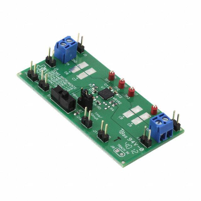
| 产品图片 |
|
| rohs | 否含铅 / 不受限制有害物质指令(RoHS)规范要求限制 |
| 产品系列 | 电源管理IC开发工具,Texas Instruments TPS74401EVM-118- |
| 数据手册 | 点击此处下载产品Datasheethttp://www.ti.com/lit/pdf/slvu143 |
| 产品型号 | TPS74401EVM-118 |
| 产品 | Evaluation Boards |
| 产品种类 | 电源管理IC开发工具 |
| 使用的IC/零件 | TPS74401 |
| 其它名称 | 296-31432 |
| 制造商产品页 | http://www.ti.com/general/docs/suppproductinfo.tsp?distId=10&orderablePartNumber=TPS74401EVM-118 |
| 商标 | Texas Instruments |
| 尺寸 | 68.6 mm x 34.2 mm |
| 工作温度 | -40°C ~ 125°C |
| 工具用于评估 | TPS74401 |
| 工厂包装数量 | 1 |
| 所含物品 | 板 |
| 板类型 | 完全填充 |
| 标准包装 | 1 |
| 每IC通道数 | 1 - 单 |
| 电压-输入 | 1.3 V ~ 5.25 V |
| 电压-输出 | 1.2V |
| 电流-输出 | 3A |
| 相关产品 | /product-detail/zh/TPS74301RGWT/296-19892-2-ND/1120763/product-detail/zh/TPS74301RGWT/296-19892-1-ND/1120806/product-detail/zh/TPS74301RGWT/296-19892-6-ND/1120848/product-detail/zh/TPS74301KTWT/296-21506-1-ND/1300145/product-detail/zh/TPS74301KTWT/296-21506-2-ND/1650227/product-detail/zh/TPS74301RGWR/TPS74301RGWR-ND/1673014/product-detail/zh/TPS74301RGWRG4/TPS74301RGWRG4-ND/1673015/product-detail/zh/TPS74301RGWTG4/TPS74301RGWTG4-ND/1673016/product-detail/zh/TPS74301KTWR/TPS74301KTWR-ND/1908296/product-detail/zh/TPS74301KTWTG3/TPS74301KTWTG3-ND/1908298/product-detail/zh/TPS74301KTWT/296-21506-6-ND/1944548 |
| 稳压器类型 | 正,可调式 |
| 类型 | LDO Voltage Regulators |
| 输入电压 | 3.3 V |
| 输出电压 | 1.2 V |


- 商务部:美国ITC正式对集成电路等产品启动337调查
- 曝三星4nm工艺存在良率问题 高通将骁龙8 Gen1或转产台积电
- 太阳诱电将投资9.5亿元在常州建新厂生产MLCC 预计2023年完工
- 英特尔发布欧洲新工厂建设计划 深化IDM 2.0 战略
- 台积电先进制程称霸业界 有大客户加持明年业绩稳了
- 达到5530亿美元!SIA预计今年全球半导体销售额将创下新高
- 英特尔拟将自动驾驶子公司Mobileye上市 估值或超500亿美元
- 三星加码芯片和SET,合并消费电子和移动部门,撤换高东真等 CEO
- 三星电子宣布重大人事变动 还合并消费电子和移动部门
- 海关总署:前11个月进口集成电路产品价值2.52万亿元 增长14.8%

PDF Datasheet 数据手册内容提取
User's Guide SLVU143–June2006 TPS74x01EVM-118 This user's guide describes the characteristics, operation, and use of the TPS74x01EVM-118 evaluation module (EVM). This EVM contains either the TPS74201, TPS74301 or TPS74401 low dropout linear regulator IC. This user's guide includes EVM specifications, recommended test setup, test results, bill of materials (BOM),andaschematicdiagram. Contents 1 Introduction.......................................................................................... 1 2 Input/OutputConnectorDescriptions............................................................ 2 3 BoardLayout........................................................................................ 5 4 BillofMaterialsandSchematic................................................................... 8 ListofFigures 1 TPS74201andTPS74401Startupwith1-msSoftStartup ................................... 4 2 TPS74201andTPS74401Startupwith10-msSoftStartup.................................. 4 3 TPS74301SimultaneousStartup................................................................. 4 4 TPS74301RatiometricStartup................................................................... 4 5 TopAssemblyLayer............................................................................... 5 6 TopLayer............................................................................................ 5 7 BottomLayer........................................................................................ 6 8 Schematic ........................................................................................... 7 ListofTables 1 TypicalPerformanceSpecificationSummary................................................... 2 2 HPA118BillofMaterials........................................................................... 8 1 Introduction TheTexasInstrumentsTPS74x01EVM-118evaluationmoduleuseseithertheTPS74201,TPS74301or TPS74401low-dropoutlinearregulatorIC.Theseregulatorsrequirealowpowerbiasvoltage,V ,anda BIAS powerinputvoltage,V .Allthreeregulatorsarecapableofprovidingoutputvoltagesdownto0.8Vand IN haveanintegratedsupervisorycircuitwithopendrainoutputthatgoestohighimpedancewhentheoutput voltagereachesregulation(powergoodorPG).TheTPS74301canprovideupto1.5Adccurrentand hasaTRACKpinwhichallowstheusertoinputarampsignalfortheoutputvoltagetofollow,effectively implementingeithersimultaneousorratiometricsequencing.TheTPS74201andTPS74401canprovide upto1.5Aand3.0Adccurrent,respectively,andhaveaSSpinwhichallowstheusertosettheoutput voltage'slinearramprate.ThegoaloftheEVMistofacilitateevaluationoftheTPS74x01ICs. SLVU143–June2006 TPS74x01EVM-118 1 SubmitDocumentationFeedback
www.ti.com Input/OutputConnectorDescriptions 1.1 Performance Specification Summary Table1providesasummaryoftheTPS74x01EVM-118performancespecifications.Allspecificationsare givenforanambienttemperatureof25(cid:176) C. Table1.TypicalPerformanceSpecificationSummary VOLTAGERANGE CURRENTRANGE CONDITION (V) (mA) MIN TYP MAX MIN TYP MAX V supply 2.62(1) 5.0 5.25 2 BIAS V supply TPS74201(HPA118-002),TPS74301 1.31(1) 3.3 5.25(2) 1500 IN (HPA118-003) TPS74401(HPA118-001) 1.32(1) 3.3 5.25(2) 3000 TPS74201(HPA118-002),TPS74301 1.18(3) 1.20 1.22(3) 1500(2) V (HPA118-003) OUT TPS74401(HPA118-001) 1.18(3) 1.20 1.22(3) 3000(2) (1) ThisistheminimumvoltagetoprovidethemaximumoutputcurrentinthetableassumingthetypicalV voltageisapplied. BIAS LoweroutputcurrentsareachievablewithlowerV andV voltages.SeedatasheetforV toV andV toV IN BIAS IN OUT BIAS OUT dropoutdata. (2) LinearregulatorpowerdissipationiscomputedasP =(V -V )· I .Asspecifiedinthedatasheet,theregulator's D IN OUT OUT packagehasafinitepowerdissipationratingdependingontheambienttemperature,boardtypeandairflow.UsingV and/or IN V voltagesotherthanthetypicalvoltagesrecommendedinthetableorusingtheEVMinanenvironmentwithanambient OUT temperaturehigherthan25(cid:176) Cwillsignificantlyreducethemaximumallowedoutputcurrent.Seethedatasheetfortheregulator package'sthermalresistancedataandrefertoapplicationnoteSLVA118entitledDigitalDesigner'sGuidetoLinearVoltage RegulatorsandThermalManagementforafullexplanation. (3) TheEVMuses– 1%feedbackresistors.Therefore,theEVMoutputtoleranceisthe– 1%internalreferencetoleranceplus2· (1 -V /V )· TOL =2· (1-0.8V/1.2V)· – 1%=0.7%or– 1.7%.Fortigheroutputtolerance,tightertolerancefeedback REF OUT FBRES resistorsmustbeused. 1.2 Modifications ToaidusercustomizationoftheEVM,theboardwasdesignedwithdeviceshaving0603orlarger footprints.Arealimplementationwouldlikelyoccupylesstotalboardspace. ChangingcomponentscanimproveordegradeEVMperformance.Forexample,addingalargeroutput capacitorwillreduceoutputvoltageundershootbutlengthenresponsetimeafteraloadtransientevent. 2 Input/Output Connector Descriptions J1–VIN/GNDThisterminalblockhasbothapositiveandgroundreturnconnectiontothepowerinput(V ) IN supply.Theleadstotheinputsupplyshouldbetwistedandkeptasshortaspossible. J2–GNDThisheaderisthereturnconnectionforthebias(V )supply. BIAS J3–VINThisheaderisapositiveconnectiontothepowerinputsupply(V ).Itsuseisrecommendedfor IN lowpower(i.e.,I =I <1A)evaluationorasavoltagetestpoint. IN OUT J4–VBIASThisheaderisthepositiveconnectionforthebias(V )supply. BIAS J5–GNDThisheaderisagroundreturnconnectiontothepowerinput(V )supply.Itsuseis IN recommendedforlowpower(i.e.,I =I <1A)evaluationorasagroundtestpoint. IN OUT J6–VOUTThisheaderisthepositiveconnectionfortheoutputloadonV .Itsuseisrecommendedfor OUT lowpower(i.e.,I =I <1A)evaluationonlyorasavoltagetestpoint. IN OUT J7–GNDThisheaderisthegroundreturnconnectionfortheoutputload.Itsuseisrecommendedforlow power(i.e.,I =I <1A)evaluationorasagroundtestpoint. IN OUT J8–VOUT/GNDThisterminalblockhasbothapositiveandgroundreturnconnectionfortheoutputload. Theleadstotheoutputloadshouldbetwistedandkeptasshortaspossible. 2 TPS74x01EVM-118 SLVU143–June2006 SubmitDocumentationFeedback
www.ti.com Input/OutputConnectorDescriptions J9–TRACKINThisheaderconnectstotopresistorofaresistordividerwhosemidpointconnectstothe TRACKINpinoftheTPS74301.Anexternalvoltagegreaterthan0.8Vmustbeappliedtothispinforthe TPS74301toproduceanoutputvoltage.ThisheaderisnotpopulatedontheTPS74201orTPS74401 EVM. J10–ENThisheaderisaconnectiontotheenablepin(EN),whichisalsoconnectedtothemiddlepinof S1.WhenS1isOFF,theENpinispulledtogroundthroughpull-downresistor. J11–GNDThisheaderisagroundconnection. JP1–1ms/Simultvs.10ms/RatioFortheTPS74301,thisjumperallowstheusertoselectthe appropriateresistordividerforeithersimultaneousorratiometricsequencing.Theseresistorshavebeen sizedpertheequationsindatasheetFigure5assuminganexternal3.3VrampsignalisappliedtoJ9 TRACKINpin.SelectingSIMULTaneousresultsintheTPS74301outputvoltagefollowingtheexternal rampsignalwithinafewmillivoltsuntiltheTPS74301reachesitsregulatedvoltage.TheTPS74301output voltagewillhavethesameramprate(dv/dt)astheexternalrampsignalbutadifferentsoft-starttime. SelectingRATIOmetricresultsintheTPS74301outputvoltagereachingitsregulatedvoltageatthesame timeastheexternallyappliedtrackingsignalreachesitsmaximumvoltage(e.g.,3.3V).Althoughthe externalrampsignalandtheTPS74301willhavedifferentramprates,theywillhavethesamesoft-start time.Leavingthejumperopenandnotapplyingthetracksignalresultsinnooutputvoltage.Leavingthe jumperopenandapplyingadctracksignalgreaterthan0.8Vresultsintheoutputvoltagerampingupwith defaultsoft-starttimeof500us. FortheTPS74201andTPS74401,thisjumperallowstheusertochooseeither1msor10mssoftstart timefortheoutputvoltage.Leavingthejumperopenresultsintheoutputvoltagerampingupwithdefault soft-starttimeof500us. S1-ThisswitchconnectstotheENpinoftheICandallowstheusertoturntheICONorOFFby connectingenabletoeitherV orgroundthroughapull-downresistor. BIAS TP1-ThisisaKelvintestpointtoV . IN TP2-ThisisaKelvintestpointtoICground. TP3-ThisisaKelvintestpointtoV . OUT 2.1 Test Setup TheabsolutemaximumvoltageallowedontheBIAS,IN,ENorTRACKpinsis6V.AllthreeTPS74x01 devicesaredesignedtooperatewithV andV lessthanorequalto5.25V.TheTPS74201and IN BIAS TPS74401canhaveV ,V ,andV appliedinanyorderwithoutcausingdamagetothedevice. IN BIAS ENABLE However,forthesoft-startfunctiontoworkasintendedcertainsequencingrulesmustbeapplied.WithS1 intheOFFposition,connectingtheENandINpinsthroughajumperwireisacceptableformost applicationsaslongasV isgreaterthan1.1VandtheramprateofbothV andV isfasterthanthe IN IN BIAS programmedsoft-startramprate.Iftheramprateoftheinputsourcesisslowerthanthesetsoft-starttime theoutputwilltracktheslowersupplyminusthedropoutvoltageuntilitreachesthesetoutputvoltage.If ENisconnectedtoBIAS(e.g.,byplacingS1intheONpositionontheEVM),thedevicewillsoft-startas programmedaslongasV ispresentbeforeV .Figure5inthedatasheetshowstheuseofanRC IN BIAS delaycircuittoholdoffV untilV hasramped.ThistechniquecanalsobeusedtodriveV from EN BIAS EN V .IfV >2.375VandV >1.1VbeforeV isappliedthenV tracksthelowerofV orV IN BIAS EN IN OUT IN SS *(1+R1/R2),whereV isthevoltageontheSSpinandisclampedto0.8V.WithS1intheOFFposition, SS anexternalcontrolsignalcanalsobeusedtoenablethedeviceafterV andV arepresent. IN BIAS TheTPS74301canalsohaveV ,V ,V ,andV sequencedinanyorderwithoutcausing IN BIAS EN TRACK damagetothedevice.Howeverforthetrackfunctiontoworkasintendedcertainsequencingrulesmust beapplied.V mustbeabove2.375VandV mustbeabove1.1V(e.g.,S1intheONpositiontying BIAS EN theBIASandENpinstogether)beforetheexternallyappliedtracksignalstartstoramp.V shouldramp IN upfasterthanthetrackingsignalsothattheexternallyappliedtrackingsignaldoesnotdrivethedevice intoV dropoutasV rampsup.ThepreferredmethodtosequencetheTPS74301isforV ,V and IN OUT IN BIAS V tobeabovetheirminimumrequiredvoltagesbeforethetrackingsignalisappliedandinitatesoutput EN voltageramping.Ifthetrackingfeatureisnotneeded,theTRACKpinshouldbeconnectedtoV . IN Configuredthisway,thedevicestartsupwithin50uswhichmayresultinlargeinrushcurrentthatcould causetheinputsupplytomomentarilydip.Also,iftheV =V rampsfasterthan500us,theoutput IN TRACK voltagemayovershoot. SLVU143–June2006 TPS74x01EVM-118 3 SubmitDocumentationFeedback
www.ti.com Input/OutputConnectorDescriptions Whenconnectingexternalloadsabove1A,useshort,twistedleadsconnectedtothescrewterminalsin ordertominimizeDCdropattheconnectorand/orinductivevoltagedipafteratransientloadisremoved. 2.2 Test Results BelowarethetestresultsatT =25(cid:176) CusingthisEVM: A A V =5V,V /I =1.2V/1A. A V =5V,V /I =1.2V/1A. IN OUT OUT IN OUT OUT Figure1.TPS74201andTPS74401Startupwith Figure2.TPS74201andTPS74401Startupwith 1-msSoftStartup 10-msSoftStartup A V =5V,V /I =1.2V/1Awith A V =5V,V /I =1.2V/1Awithwith IN OUT OUT IN OUT OUT TRACK-INsignalprovidedbyTPS74201 TRACK-INsignalprovidedbyTPS74201 configuredfor3.3Vand10msstartup configuredfor3.3Vand10msstartup Figure3.TPS74301SimultaneousStartup Figure4.TPS74301RatiometricStartup 4 TPS74x01EVM-118 SLVU143–June2006 SubmitDocumentationFeedback
www.ti.com BoardLayout 3 Board Layout Boardlayoutiscriticalforallswitchmodepowersupplies.Figure5,Figure6,andFigure7showtheboard layoutfortheHPA118PWB.Theswitchingnodeswithhigh-frequencynoiseareisolatedfromthe noise-sensitivefeedbackcircuitry,andcarefulattentionhasbeengiventotheroutingofhigh-frequency currentloops.Seethedatasheetformorespecificlayoutguidelines. Figure5.TopAssemblyLayer Figure6.TopLayer SLVU143–June2006 TPS74x01EVM-118 5 SubmitDocumentationFeedback
www.ti.com BoardLayout Figure7.BottomLayer 6 TPS74x01EVM-118 SLVU143–June2006 SubmitDocumentationFeedback
www.ti.com BoardLayout Figure8.Schematic SLVU143–June2006 TPS74x01EVM-118 7 SubmitDocumentationFeedback
www.ti.com BillofMaterialsandSchematic 4 Bill of Materials and Schematic 4.1 Bill of Materials Table2.HPA118BillofMaterials Count RefDes Value Description Size PartNumber MFR -001 -002 -003 2 2 2 C1,C2 1.0m F Capacitor,Ceramic,25V,X5R,10% 0603 C1608X5R1E105K TDK 1 1 1 C3 4.7m F Capacitor,Ceramic,6.3V,X5R, 0603 C1608X5R0J475K TDK 10% 1 1 0 C4 1000 Capacitor,Ceramic,50V,C0G,5% 0603 C1608C0G1H102JB TDK pF 1 1 0 C5 0.01 Capacitor,Ceramic,50V,X7R,10% 0603 C1608X7R1H103KB TDK m F 0 0 0 C6,C7, Open Capacitor,Multi-pattern,603-Dcase 7343(D) C8,C9 2 2 2 J1,J8 TerminalBlock,2pin,6A,3.5mm 0.27x0.25 ED1514 OST 8 8 8 J2-J7, Header,2pin,100milspacing, 0.100x2 PTC36SAAN Sullins J10,J11 (36-pinstrip) 0 0 1 J9 Header,2pin,100milspacing, 0.100x2 PTC36SAAN Sullins (36-pinstrip) 1 1 1 JP1 Header,3pin,100milspacing, 0.100x3 PTC36SAAN Sullins (36-pinstrip) 1 1 1 R1 2.49 Resistor,Chip,1/16W,1% 0603 Std Std kW 1 1 1 R2 4.99 Resistor,Chip,1/16W,1% 0603 Std Std kW 1 1 1 R3 10.0 Resistor,Chip,1/16W,1% 0603 Std Std kW 0 0 1 R4 4.99 Resistor,Chip,1/16W,1% 0603 Std Std kW 0 0 1 R5 10.0 Resistor,Chip,1/16W,1% 0603 Std Std kW 0 0 1 R6 1.78 Resistor,Chip,1/16W,1% 0603 Std Std kW 1 1 1 R7 100kW Resistor,Chip,1/16W,1% 0603 Std Std 1 1 1 S1 Switch,1P2T,Slide,PCmount, 0.46x0.16 EG1218 E_Switch 200mA 4 4 4 TP1- TestPoint,Red,ThruHoleColor 0.100x0.100 5000 Keystone TP4 Keyed 1 0 0 U1 IC,3.0ALDOWithProgrammable QFN-20 TPS74401RGW TI SoftStart 0 1 0 IC,1.5ALDOWithProgrammable QFN-20 TPS74201RGW TI SoftStart 0 0 1 IC,1.5ALDOWithProgrammable QFN-20 TPS74301RGW TI Sequencing 1 1 1 -- PCB,2.7Inx1.345Inx0.062In HPA118 Any 1 1 1 -- Shunt,100mil,Black 0.100 929950-00 8 TPS74x01EVM-118 SLVU143–June2006 SubmitDocumentationFeedback
EVALUATIONBOARD/KITIMPORTANTNOTICE TexasInstruments(TI)providestheenclosedproduct(s)underthefollowingconditions: Thisevaluationboard/kitisintendedforuseforENGINEERINGDEVELOPMENT,DEMONSTRATION,OREVALUATION PURPOSESONLYandisnotconsideredbyTItobeafinishedend-productfitforgeneralconsumeruse.Personshandlingthe product(s)musthaveelectronicstrainingandobservegoodengineeringpracticestandards.Assuch,thegoodsbeingprovidedare notintendedtobecompleteintermsofrequireddesign-,marketing-,and/ormanufacturing-relatedprotectiveconsiderations, includingproductsafetyandenvironmentalmeasurestypicallyfoundinendproductsthatincorporatesuchsemiconductor componentsorcircuitboards.Thisevaluationboard/kitdoesnotfallwithinthescopeoftheEuropeanUniondirectivesregarding electromagneticcompatibility,restrictedsubstances(RoHS),recycling(WEEE),FCC,CEorUL,andthereforemaynotmeetthe technicalrequirementsofthesedirectivesorotherrelateddirectives. Shouldthisevaluationboard/kitnotmeetthespecificationsindicatedintheUser’sGuide,theboard/kitmaybereturnedwithin30 daysfromthedateofdeliveryforafullrefund.THEFOREGOINGWARRANTYISTHEEXCLUSIVEWARRANTYMADEBY SELLERTOBUYERANDISINLIEUOFALLOTHERWARRANTIES,EXPRESSED,IMPLIED,ORSTATUTORY,INCLUDING ANYWARRANTYOFMERCHANTABILITYORFITNESSFORANYPARTICULARPURPOSE. Theuserassumesallresponsibilityandliabilityforproperandsafehandlingofthegoods.Further,theuserindemnifiesTIfromall claimsarisingfromthehandlingoruseofthegoods.Duetotheopenconstructionoftheproduct,itistheuser’sresponsibilityto takeanyandallappropriateprecautionswithregardtoelectrostaticdischarge. EXCEPTTOTHEEXTENTOFTHEINDEMNITYSETFORTHABOVE,NEITHERPARTYSHALLBELIABLETOTHEOTHER FORANYINDIRECT,SPECIAL,INCIDENTAL,ORCONSEQUENTIALDAMAGES. TIcurrentlydealswithavarietyofcustomersforproducts,andthereforeourarrangementwiththeuserisnotexclusive. TIassumesnoliabilityforapplicationsassistance,customerproductdesign,softwareperformance,orinfringementof patentsorservicesdescribedherein. PleasereadtheUser’sGuideand,specifically,theWarningsandRestrictionsnoticeintheUser’sGuidepriortohandlingthe product.Thisnoticecontainsimportantsafetyinformationabouttemperaturesandvoltages.ForadditionalinformationonTI’s environmentaland/orsafetyprograms,pleasecontacttheTIapplicationengineerorvisitwww.ti.com/esh. NolicenseisgrantedunderanypatentrightorotherintellectualpropertyrightofTIcoveringorrelatingtoanymachine,process,or combinationinwhichsuchTIproductsorservicesmightbeorareused. FCCWarning Thisevaluationboard/kitisintendedforuseforENGINEERINGDEVELOPMENT,DEMONSTRATION,OREVALUATION PURPOSESONLYandisnotconsideredbyTItobeafinishedend-productfitforgeneralconsumeruse.Itgenerates,uses,and canradiateradiofrequencyenergyandhasnotbeentestedforcompliancewiththelimitsofcomputingdevicespursuanttopart15 ofFCCrules,whicharedesignedtoprovidereasonableprotectionagainstradiofrequencyinterference.Operationofthis equipmentinotherenvironmentsmaycauseinterferencewithradiocommunications,inwhichcasetheuserathisownexpense willberequiredtotakewhatevermeasuresmayberequiredtocorrectthisinterference.
EVMWARNINGSANDRESTRICTIONS ItisimportanttooperatethisEVMwithintheinputvoltageof5Vandtheoutputvoltageof3.3V. Exceedingthespecifiedinputrangemaycauseunexpectedoperationand/orirreversibledamage totheEVM.Iftherearequestionsconcerningtheinputrange,pleasecontactaTIfield representativepriortoconnectingtheinputpower. Applyingloadsoutsideofthespecifiedoutputrangemayresultinunintendedoperationand/or possiblepermanentdamagetotheEVM.PleaseconsulttheEVMUser'sGuidepriorto connectinganyloadtotheEVMoutput.Ifthereisuncertaintyastotheloadspecification,please contactaTIfieldrepresentative. Duringnormaloperation,somecircuitcomponentsmayhavecasetemperaturesgreaterthan 25(cid:176) C.TheEVMisdesignedtooperateproperlywithcertaincomponentsabove25(cid:176) Caslongas theinputandoutputrangesaremaintained.Thesecomponentsincludebutarenotlimitedto linearregulators,switchingtransistors,passtransistors,andcurrentsenseresistors.Thesetypes ofdevicescanbeidentifiedusingtheEVMschematiclocatedintheEVMUser'sGuide.When placingmeasurementprobesnearthesedevicesduringoperation,pleasebeawarethatthese devicesmaybeverywarmtothetouch. MailingAddress:TexasInstruments,PostOfficeBox655303,Dallas,Texas75265 Copyright©2006,TexasInstrumentsIncorporated
IMPORTANTNOTICE TexasInstrumentsIncorporatedanditssubsidiaries(TI)reservetherighttomakecorrections,modifications,enhancements, improvements,andotherchangestoitsproductsandservicesatanytimeandtodiscontinueanyproductorservicewithoutnotice. Customersshouldobtainthelatestrelevantinformationbeforeplacingordersandshouldverifythatsuchinformationiscurrentand complete.AllproductsaresoldsubjecttoTI’stermsandconditionsofsalesuppliedatthetimeoforderacknowledgment. TIwarrantsperformanceofitshardwareproductstothespecificationsapplicableatthetimeofsaleinaccordancewithTI’s standardwarranty.TestingandotherqualitycontroltechniquesareusedtotheextentTIdeemsnecessarytosupportthis warranty.Exceptwheremandatedbygovernmentrequirements,testingofallparametersofeachproductisnotnecessarily performed. TIassumesnoliabilityforapplicationsassistanceorcustomerproductdesign.Customersareresponsiblefortheirproductsand applicationsusingTIcomponents.Tominimizetherisksassociatedwithcustomerproductsandapplications,customersshould provideadequatedesignandoperatingsafeguards. TIdoesnotwarrantorrepresentthatanylicense,eitherexpressorimplied,isgrantedunderanyTIpatentright,copyright,mask workright,orotherTIintellectualpropertyrightrelatingtoanycombination,machine,orprocessinwhichTIproductsorservices areused.InformationpublishedbyTIregardingthird-partyproductsorservicesdoesnotconstitutealicensefromTItousesuch productsorservicesorawarrantyorendorsementthereof.Useofsuchinformationmayrequirealicensefromathirdpartyunder thepatentsorotherintellectualpropertyofthethirdparty,oralicensefromTIunderthepatentsorotherintellectualpropertyofTI. ReproductionofinformationinTIdatabooksordatasheetsispermissibleonlyifreproductioniswithoutalterationandis accompaniedbyallassociatedwarranties,conditions,limitations,andnotices.Reproductionofthisinformationwithalterationisan unfairanddeceptivebusinesspractice.TIisnotresponsibleorliableforsuchaltereddocumentation. ResaleofTIproductsorserviceswithstatementsdifferentfromorbeyondtheparametersstatedbyTIforthatproductorservice voidsallexpressandanyimpliedwarrantiesfortheassociatedTIproductorserviceandisanunfairanddeceptivebusiness practice.TIisnotresponsibleorliableforanysuchstatements. TIproductsarenotauthorizedforuseinsafety-criticalapplications(suchaslifesupport)whereafailureoftheTIproductwould reasonablybeexpectedtocauseseverepersonalinjuryordeath,unlessofficersofthepartieshaveexecutedanagreement specificallygoverningsuchuse.Buyersrepresentthattheyhaveallnecessaryexpertiseinthesafetyandregulatoryramifications oftheirapplications,andacknowledgeandagreethattheyaresolelyresponsibleforalllegal,regulatoryandsafety-related requirementsconcerningtheirproductsandanyuseofTIproductsinsuchsafety-criticalapplications,notwithstandingany applications-relatedinformationorsupportthatmaybeprovidedbyTI.Further,BuyersmustfullyindemnifyTIandits representativesagainstanydamagesarisingoutoftheuseofTIproductsinsuchsafety-criticalapplications. TIproductsareneitherdesignednorintendedforuseinmilitary/aerospaceapplicationsorenvironmentsunlesstheTIproductsare specificallydesignatedbyTIasmilitary-gradeor"enhancedplastic."OnlyproductsdesignatedbyTIasmilitary-grademeetmilitary specifications.BuyersacknowledgeandagreethatanysuchuseofTIproductswhichTIhasnotdesignatedasmilitary-gradeis solelyattheBuyer'srisk,andthattheyaresolelyresponsibleforcompliancewithalllegalandregulatoryrequirementsin connectionwithsuchuse. TIproductsareneitherdesignednorintendedforuseinautomotiveapplicationsorenvironmentsunlessthespecificTIproducts aredesignatedbyTIascompliantwithISO/TS16949requirements.Buyersacknowledgeandagreethat,iftheyuseany non-designatedproductsinautomotiveapplications,TIwillnotberesponsibleforanyfailuretomeetsuchrequirements. FollowingareURLswhereyoucanobtaininformationonotherTexasInstrumentsproductsandapplicationsolutions: Products Applications Amplifiers amplifier.ti.com Audio www.ti.com/audio DataConverters dataconverter.ti.com Automotive www.ti.com/automotive DSP dsp.ti.com Broadband www.ti.com/broadband Interface interface.ti.com DigitalControl www.ti.com/digitalcontrol Logic logic.ti.com Military www.ti.com/military PowerMgmt power.ti.com OpticalNetworking www.ti.com/opticalnetwork Microcontrollers microcontroller.ti.com Security www.ti.com/security RFID www.ti-rfid.com Telephony www.ti.com/telephony LowPower www.ti.com/lpw Video&Imaging www.ti.com/video Wireless Wireless www.ti.com/wireless MailingAddress:TexasInstruments,PostOfficeBox655303,Dallas,Texas75265 Copyright©2007,TexasInstrumentsIncorporated
 Datasheet下载

