ICGOO在线商城 > TPS65030EVM-162
- 型号: TPS65030EVM-162
- 制造商: Texas Instruments
- 库位|库存: xxxx|xxxx
- 要求:
| 数量阶梯 | 香港交货 | 国内含税 |
| +xxxx | $xxxx | ¥xxxx |
查看当月历史价格
查看今年历史价格
TPS65030EVM-162产品简介:
ICGOO电子元器件商城为您提供TPS65030EVM-162由Texas Instruments设计生产,在icgoo商城现货销售,并且可以通过原厂、代理商等渠道进行代购。 提供TPS65030EVM-162价格参考以及Texas InstrumentsTPS65030EVM-162封装/规格参数等产品信息。 你可以下载TPS65030EVM-162参考资料、Datasheet数据手册功能说明书, 资料中有TPS65030EVM-162详细功能的应用电路图电压和使用方法及教程。
| 参数 | 数值 |
| 产品目录 | 编程器,开发系统半导体 |
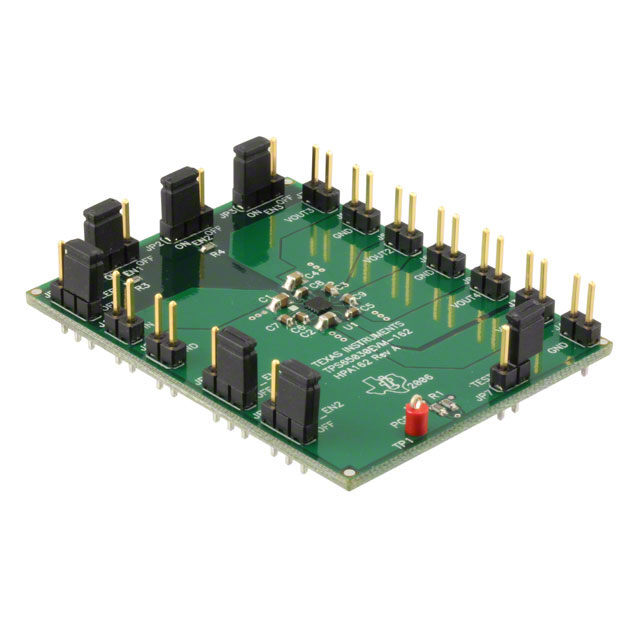
| 描述 | EVAL MODULE FOR TPS65030-162电源管理IC开发工具 PWR MGMT IC |
| 产品分类 | |
| 品牌 | Texas Instruments |
| 产品手册 | |
| 产品图片 |
|
| rohs | 否含铅 / 不符合限制有害物质指令(RoHS)规范要求 |
| 产品系列 | 电源管理IC开发工具,Texas Instruments TPS65030EVM-162- |
| 数据手册 | 点击此处下载产品Datasheethttp://www.ti.com/lit/pdf/slvu168 |
| 产品型号 | TPS65030EVM-162 |
| 主要用途 | DC/DC,LDO 步降 |
| 产品 | Evaluation Boards |
| 产品种类 | 电源管理IC开发工具 |
| 使用的IC/零件 | TPS65030 |
| 其它名称 | 296-31427 |
| 制造商产品页 | http://www.ti.com/general/docs/suppproductinfo.tsp?distId=10&orderablePartNumber=TPS65030EVM-162 |
| 功率-输出 | - |
| 商标 | Texas Instruments |
| 尺寸 | 58.4 mm x 45.7 mm |
| 工具用于评估 | TPS65030 |
| 工厂包装数量 | 1 |
| 所含物品 | 板 |
| 板类型 | 完全填充 |
| 标准包装 | 1 |
| 电压-输入 | 3 V ~ 5.25 V |
| 电压-输出 | 1.5V,5V,1.8V,3.3V |
| 电流-输出 | 200mA,100mA,60mA,22mA |
| 相关产品 | /product-detail/zh/TPS65030YZKT/296-19560-2-ND/1004614/product-detail/zh/TPS65030YZKT/296-19560-1-ND/1004637/product-detail/zh/TPS65030YZKR/TPS65030YZKR-ND/1672432 |
| 稳压器拓扑 | 降压 |
| 类型 | PMIC Solutions |
| 输入电压 | 3 V to 5 V |
| 输出和类型 | 4,非隔离 |
| 输出电压 | 5 V |
| 频率-开关 | 1MHz |




- 商务部:美国ITC正式对集成电路等产品启动337调查
- 曝三星4nm工艺存在良率问题 高通将骁龙8 Gen1或转产台积电
- 太阳诱电将投资9.5亿元在常州建新厂生产MLCC 预计2023年完工
- 英特尔发布欧洲新工厂建设计划 深化IDM 2.0 战略
- 台积电先进制程称霸业界 有大客户加持明年业绩稳了
- 达到5530亿美元!SIA预计今年全球半导体销售额将创下新高
- 英特尔拟将自动驾驶子公司Mobileye上市 估值或超500亿美元
- 三星加码芯片和SET,合并消费电子和移动部门,撤换高东真等 CEO
- 三星电子宣布重大人事变动 还合并消费电子和移动部门
- 海关总署:前11个月进口集成电路产品价值2.52万亿元 增长14.8%


PDF Datasheet 数据手册内容提取
User's Guide SLVU168–June2006 TPS65030EVM-162 This user’s guide describes the characteristics, operation, and use of the TPS65030EVM-162 evaluation module (EVM). This EVM demonstrates the Texas Instruments TPS65030 power management IC for USB On-The-Go (USB-OTG) applications. This user’s guide includes setup instructions, a schematic diagram, a bill ofmaterials(BOM),andPCBlayoutdrawingsfortheevaluationmodule. Contents 1 Introduction.......................................................................................... 1 2 Setup................................................................................................. 2 3 BoardLayout........................................................................................ 4 4 SchematicandBillofMaterials ................................................................. 10 ListofFigures 1 AssemblyLayer..................................................................................... 5 2 TopLayerRouting.................................................................................. 6 3 Layer2Routing..................................................................................... 7 4 Layer3Routing..................................................................................... 8 5 BottomLayerRouting.............................................................................. 9 6 TPS65030EVM-162Schematic................................................................. 10 ListofTables 1 TPS65030EVM-162BillofMaterials........................................................... 11 1 Introduction TheTexasInstrumentsTPS65030EVM-162evaluationmodule(EVM)helpsdesignersevaluatethe operationandperformanceoftheTPS65030powermanagementICforUSB-OTGapplications.The TPS65030containsfourregulatedoutputvoltagesandoperatesfroma3-Vto5-Vinputsupply.The suppliedoutputsprovideallthenecessarysupplyvoltagesforUSB-OTG.TheEVMhasjumpersforall inputpinsforeasyevaluationoftheEN_,SW_,SLEEP,andTESTSRPinputs.Apower-goodoutput (PGood)isavailableforeasypowersupplysequencingapplications.The1-MHzchargepumpdesignas wellthe25-ballchipscalepackageprovideasmallfootprintsolution. 1.1 Related Documentation From Texas Instruments TPS65030datasheet(SLVS620) SLVU168–June2006 TPS65030EVM-162 1 SubmitDocumentationFeedback
www.ti.com Setup 2 Setup ThissectiondescribesthejumpersandconnectorsontheEVMaswellashowtoproperlyconnect,set up,andusetheTPS65030EVM-162. 2.1 Input/Output Connector Descriptions 2.1.1 J1—VIN Thisisthepositiveinputvoltageconnectiontotheconverter.TheEVMoperatesfromanysupplyvoltage between3Vand5V.Theleadstotheinputsupplyshouldbetwistedtogetherandkeptasshortas possibletominimizeEMItransmissionandinputvoltagedroop. 2.1.2 J2—GND Thisistheinputreturnconnectionfortheinputpowersupply. 2.1.3 J3—VOUT1 ThisisthepositiveoutputvoltageconnectionfromtheVBUSoutput.Thischargepumpregulatoroutput regulatesto5Vandsuppliesupto100mA. 2.1.4 J4—GND ThisistheoutputgroundconnectionfortheVOUT1chargepump. 2.1.5 J5—VOUT2 ThisisthepositiveoutputvoltageconnectionfromtheVOUT2output.Thischargepumpregulatoroutput regulatesto3.3Vandsuppliesupto22mA. 2.1.6 J6—GND ThisistheoutputgroundconnectionfortheVOUT2chargepumpandVOUT4LDOregulators. 2.1.7 J7—VOUT3 ThisisthepositiveoutputvoltageconnectionfromtheVOUT3output.Thischargepumpregulatoroutput regulatesto1.5Vandsuppliesupto200mA. 2.1.8 J8—GND ThisistheoutputgroundconnectionfortheVOUT3chargepump. 2.1.9 J9—VOUT4 ThisisthepositiveoutputvoltageconnectionfromtheVOUT4output.ThisLDOregulatoroutputregulates to1.8Vandsuppliesupto60mA. 2.1.10 JP1—VBUSConverterEnable JP1isusedtoenabletheVBUSconverter(VOUT1).PlaceashuntintheONpositiontoturntheVBUS converteron.WhentheVBUSconverterisenabled,VOUT1regulatesto5Vandsuppliesupto100mA. PlaceashuntintheOFFpositiontoturntheVBUSconverteroff.VOUT1ishighimpedancewhenthe VBUSconverterisdisabled. 2 TPS65030EVM-162 SLVU168–June2006 SubmitDocumentationFeedback
www.ti.com Setup 2.1.11 JP2—VOUT2andVOUT3ConverterEnable JP2isusedtoenabletheVOUT2andVOUT3converters.PlaceashuntintheONpositiontoturnthe VOUT2andVOUT3converterson.WhentheVOUT2andVOUT3convertersareenabled,VOUT2 regulatesto3.3Vandsuppliesupto22mA,andVOUT3regulatesto1.5Vandsuppliesupto200mA. PlaceashuntintheOFFpositiontoturntheVOUT2andVOUT3convertersoff.VOUT2andVOUT3are highimpedancewhentheconvertersaredisabled. 2.1.12 JP3—VOUT4ConverterEnable JP3isusedtoenabletheVOUT4LDO.PlaceashuntintheONpositiontoturntheVOUT4LDOon. WhentheVOUT4LDOisenabled,VOUT4regulatesto1.8Vandsuppliesupto60mA.Placeashuntin theOFFpositiontoturntheVOUT4LDOoff.VOUT4ishighimpedancewhentheLDOisdisabled. 2.1.13 JP4—SleepModeEnable JP4isusedtoenablethesleepmodefeatureforVOUT2,VOUT3,andVOUT4.PlaceashuntintheON positiontoenablesleepmode.Duringsleepmode,VOUT2,VOUT3,andVOUT4areregulatedusing low-powerLDOs.VOUT2regulatesto3V,VOUT3regulatesto1.5VandVOUT4regulatesto1.8V.All threeoutputssupplyupto100m A.PlaceashuntintheOFFpositiontoturnthesleepmodeoffandreturn tonormaloperation. 2.1.14 JP5—VOUT3SwitchoverEnable JP5isusedtoenabletheVOUT3switchoverfunction.PlaceashuntintheONpositiontoenablethe switchoverfunction.Whentheswitchoverfunctionisenabled,VOUT3ispoweredfromVBUSunless VBUSisbelow4.3V.WhenVBUSislessthan4.3V,VOUT3ispoweredfromVIN.Ifsleepmodeis enabled,VOUT3ispoweredfromVINregardlessofthisjumperlocation.PlaceashuntintheOFF positiontodisabletheVOUT3switchoverfunction.VOUT3isalwayspoweredfromVINwhenthe switchovermodeisdisabled. 2.1.15 JP6–VOUT2SwitchoverEnable JP6isusedtoenabletheVOUT2switchoverfunction.PlaceashuntintheONpositiontoenablethe switchoverfunction.Whentheswitchoverfunctionisenabled,VOUT2ispoweredfromVBUSunless VBUSisbelow4.3V.Inthiscase,VOUT2ispoweredfromVIN.Ifsleepmodeisenabled,VOUT2is poweredfromVINregardlessofthisjumperlocation.PlaceashuntintheOFFpositiontodisablethe VOUT2switchoverfunction.VOUT2isalwayspoweredfromVINwhentheswitchovermodeisdisabled. 2.1.16 JP7—Current-LimitSelectionandTESTModeIndicator JP7isusedfortwofunctions.Thefirstistoselectthecurrent-limitduringstart-up.Placeashuntacross thejumpertoselecta1-mAcurrentlimitduringstart-up.Removetheshunttoselecta100-mAcurrent limitduringstart-up. ThesecondfunctionforJP7issignaloutputduringtestmode.Iftestmodeisenabled,pin1ofJP7goes eitherhighorlowtoindicateconnectivitystatus.Seethe“TESTInputSRPEnable”sectionofthe TPS65030datasheet(SLVS620)ordetailsonenteringtestmodeandconnectivitystatusindicator. 2.1.17 TP1—PowerGoodOutput TP1isusedtomonitorthePGoodsignal.TP1goeshighaminimum3.1msafterVOUT2,VOUT3,and VOUT4exceedthePGoodthresholds.Thethresholdsare85%oftheregulationvoltageforVOUT2,and 90%oftheregulationvoltageforVOUT3andVOUT4.ThePGOODpingoeslowifoneoftheseoutputs fallsbelowitsthreshold.OutputsthataredisabledareignoredbythePGoodcircuitry. SLVU168–June2006 TPS65030EVM-162 3 SubmitDocumentationFeedback
www.ti.com BoardLayout 2.2 Setup 1. ConfigureJP1toenableordisableVBUSasdesired 2. ConfigureJP2toenableordisableVOUT2andVOUT3asdesired 3. ConfigureJP3toenableordisableVOUT4asdesired 4. ConfigureJP4toenableordisablesleepmodeasdesired 5. ConfigureJP5toenableordisableVOUT3switchovermodeasdesired 6. ConfigureJP6toenableordisableVOUT2switchovermodeasdesired 7. ConfigureJP7tosetthestart-upcurrent-limitasdesired 8. ConnecttheinputvoltagereturntoJ2. 9. ConnectthepositiveinputvoltagetoJ1. 10.Turnoninputvoltage. 11.TheoutputvoltagesthatwereenabledbyJP1,JP2,andJP3areavailable. 3 Board Layout ThissectionprovidestheTPS65030EVM-162boardlayoutandillustrations. 4 TPS65030EVM-162 SLVU168–June2006 SubmitDocumentationFeedback
www.ti.com BoardLayout 3.1 Layout Figure1throughFigure5showtheboardlayoutfortheTPS65030EVM-162PCB. Figure1.AssemblyLayer SLVU168–June2006 TPS65030EVM-162 5 SubmitDocumentationFeedback
www.ti.com BoardLayout Figure2.TopLayerRouting 6 TPS65030EVM-162 SLVU168–June2006 SubmitDocumentationFeedback
www.ti.com BoardLayout Figure3.Layer2Routing SLVU168–June2006 TPS65030EVM-162 7 SubmitDocumentationFeedback
www.ti.com BoardLayout Figure4. Layer3Routing 8 TPS65030EVM-162 SLVU168–June2006 SubmitDocumentationFeedback
www.ti.com BoardLayout Figure5.BottomLayerRouting SLVU168–June2006 TPS65030EVM-162 9 SubmitDocumentationFeedback
www.ti.com SchematicandBillofMaterials 4 Schematic and Bill of Materials ThissectionprovidestheTPS65030EVM-162schematicandbillofmaterials. 4.1 Schematic Figure6.TPS65030EVM-162Schematic 10 TPS65030EVM-162 SLVU168–June2006 SubmitDocumentationFeedback
www.ti.com SchematicandBillofMaterials 4.2 Bill of Materials Table1.TPS65030EVM-162BillofMaterials COUN RefDes Value Description Size PartNumber MFR T 1 C1 22uF Capacitor,Ceramic,6.3V,X5R,20% 0805 C2012X5R0J226M TDK 1 C2 4.7m F Capacitor,Ceramic,6.3V,X5R,10% 0805 C2012X5R0J475K TDK 5 C3,C5–C8 1.0m F Capacitor,Ceramic,16V,X7R,10% 0603 C1608X7R1C105K TDK 1 C4 10m F Capacitor,Ceramic,6.3V,X5R,20% 0805 C2012X5R0J106M TDK 1 C9 0.1m F Capacitor,Ceramic,50V,X7R,10% 0603 C1608X7R1H104K TDK 9 J1–J9 Header,2pin,100milspacing,(36-pinstrip) 0.100· 2 PTC36SAAN Sullins 6 JP1–JP6 Header,3pin,100milspacing,(36-pinstrip) 0.100· 3 PTC36SAAN Sullins 1 JP7 Header,2pin,100milspacing,(36-pinstrip) 0.100· 2 PTC36SAAN Sullins 4 R1–R4 1.00M Resistor,Chip,1/16W,1% 0603 Std Std 1 TP1 TestPoint,Red,ThruHoleColorKeyed 0.100· 0.100 5000 Keystone 1 U1 IC,PowerManagementforUSB-OTG BGA-25 TPS65030YZK TI 1 — PCB,2.3In· 1.8In· 0.062In HPA162 Any 7 — Shunt,100mil,Black 0.100 929950-00 3M SLVU168–June2006 TPS65030EVM-162 11 SubmitDocumentationFeedback
EVALUATIONBOARD/KITIMPORTANTNOTICE TexasInstruments(TI)providestheenclosedproduct(s)underthefollowingconditions: Thisevaluationboard/kitisintendedforuseforENGINEERINGDEVELOPMENT,DEMONSTRATION,OREVALUATION PURPOSESONLYandisnotconsideredbyTItobeafinishedend-productfitforgeneralconsumeruse.Personshandlingthe product(s)musthaveelectronicstrainingandobservegoodengineeringpracticestandards.Assuch,thegoodsbeingprovidedare notintendedtobecompleteintermsofrequireddesign-,marketing-,and/ormanufacturing-relatedprotectiveconsiderations, includingproductsafetyandenvironmentalmeasurestypicallyfoundinendproductsthatincorporatesuchsemiconductor componentsorcircuitboards.Thisevaluationboard/kitdoesnotfallwithinthescopeoftheEuropeanUniondirectivesregarding electromagneticcompatibility,restrictedsubstances(RoHS),recycling(WEEE),FCC,CEorUL,andthereforemaynotmeetthe technicalrequirementsofthesedirectivesorotherrelateddirectives. Shouldthisevaluationboard/kitnotmeetthespecificationsindicatedintheUser’sGuide,theboard/kitmaybereturnedwithin30 daysfromthedateofdeliveryforafullrefund.THEFOREGOINGWARRANTYISTHEEXCLUSIVEWARRANTYMADEBY SELLERTOBUYERANDISINLIEUOFALLOTHERWARRANTIES,EXPRESSED,IMPLIED,ORSTATUTORY,INCLUDING ANYWARRANTYOFMERCHANTABILITYORFITNESSFORANYPARTICULARPURPOSE. Theuserassumesallresponsibilityandliabilityforproperandsafehandlingofthegoods.Further,theuserindemnifiesTIfromall claimsarisingfromthehandlingoruseofthegoods.Duetotheopenconstructionoftheproduct,itistheuser’sresponsibilityto takeanyandallappropriateprecautionswithregardtoelectrostaticdischarge. EXCEPTTOTHEEXTENTOFTHEINDEMNITYSETFORTHABOVE,NEITHERPARTYSHALLBELIABLETOTHEOTHER FORANYINDIRECT,SPECIAL,INCIDENTAL,ORCONSEQUENTIALDAMAGES. TIcurrentlydealswithavarietyofcustomersforproducts,andthereforeourarrangementwiththeuserisnotexclusive. TIassumesnoliabilityforapplicationsassistance,customerproductdesign,softwareperformance,orinfringementof patentsorservicesdescribedherein. PleasereadtheUser’sGuideand,specifically,theWarningsandRestrictionsnoticeintheUser’sGuidepriortohandlingthe product.Thisnoticecontainsimportantsafetyinformationabouttemperaturesandvoltages.ForadditionalinformationonTI’s environmentaland/orsafetyprograms,pleasecontacttheTIapplicationengineerorvisitwww.ti.com/esh. NolicenseisgrantedunderanypatentrightorotherintellectualpropertyrightofTIcoveringorrelatingtoanymachine,process,or combinationinwhichsuchTIproductsorservicesmightbeorareused. FCCWarning Thisevaluationboard/kitisintendedforuseforENGINEERINGDEVELOPMENT,DEMONSTRATION,OREVALUATION PURPOSESONLYandisnotconsideredbyTItobeafinishedend-productfitforgeneralconsumeruse.Itgenerates,uses,and canradiateradiofrequencyenergyandhasnotbeentestedforcompliancewiththelimitsofcomputingdevicespursuanttopart15 ofFCCrules,whicharedesignedtoprovidereasonableprotectionagainstradiofrequencyinterference.Operationofthis equipmentinotherenvironmentsmaycauseinterferencewithradiocommunications,inwhichcasetheuserathisownexpense willberequiredtotakewhatevermeasuresmayberequiredtocorrectthisinterference. EVMWARNINGSANDRESTRICTIONS ItisimportanttooperatethisEVMwithintheinputvoltagerangeof3Vto5Vandthemaximumoutputvoltageof5V. Exceedingthespecifiedinputrangemaycauseunexpectedoperationand/orirreversibledamagetotheEVM.Ifthereare questionsconcerningtheinputrange,pleasecontactaTIfieldrepresentativepriortoconnectingtheinputpower. Applyingloadsoutsideofthespecifiedoutputrangemayresultinunintendedoperationand/orpossiblepermanentdamagetothe EVM.PleaseconsulttheEVMUser'sGuidepriortoconnectinganyloadtotheEVMoutput.Ifthereisuncertaintyastotheload specification,pleasecontactaTIfieldrepresentative. Duringnormaloperation,somecircuitcomponentsmayhavecasetemperaturesgreaterthan50(cid:176) C.TheEVMisdesignedto operateproperlywithcertaincomponentsabove50(cid:176) Caslongastheinputandoutputrangesaremaintained.Thesecomponents includebutarenotlimitedtolinearregulators,switchingtransistors,passtransistors,andcurrentsenseresistors.Thesetypesof devicescanbeidentifiedusingtheEVMschematiclocatedintheEVMUser'sGuide.Whenplacingmeasurementprobesnear thesedevicesduringoperation,pleasebeawarethatthesedevicesmaybeverywarmtothetouch. MailingAddress:TexasInstruments,PostOfficeBox655303,Dallas,Texas75265 Copyright©2006,TexasInstrumentsIncorporated
IMPORTANTNOTICE TexasInstrumentsIncorporatedanditssubsidiaries(TI)reservetherighttomakecorrections,modifications,enhancements, improvements,andotherchangestoitsproductsandservicesatanytimeandtodiscontinueanyproductorservicewithoutnotice. Customersshouldobtainthelatestrelevantinformationbeforeplacingordersandshouldverifythatsuchinformationiscurrentand complete.AllproductsaresoldsubjecttoTI’stermsandconditionsofsalesuppliedatthetimeoforderacknowledgment. TIwarrantsperformanceofitshardwareproductstothespecificationsapplicableatthetimeofsaleinaccordancewithTI’s standardwarranty.TestingandotherqualitycontroltechniquesareusedtotheextentTIdeemsnecessarytosupportthis warranty.Exceptwheremandatedbygovernmentrequirements,testingofallparametersofeachproductisnotnecessarily performed. TIassumesnoliabilityforapplicationsassistanceorcustomerproductdesign.Customersareresponsiblefortheirproductsand applicationsusingTIcomponents.Tominimizetherisksassociatedwithcustomerproductsandapplications,customersshould provideadequatedesignandoperatingsafeguards. TIdoesnotwarrantorrepresentthatanylicense,eitherexpressorimplied,isgrantedunderanyTIpatentright,copyright,mask workright,orotherTIintellectualpropertyrightrelatingtoanycombination,machine,orprocessinwhichTIproductsorservices areused.InformationpublishedbyTIregardingthird-partyproductsorservicesdoesnotconstitutealicensefromTItousesuch productsorservicesorawarrantyorendorsementthereof.Useofsuchinformationmayrequirealicensefromathirdpartyunder thepatentsorotherintellectualpropertyofthethirdparty,oralicensefromTIunderthepatentsorotherintellectualpropertyofTI. ReproductionofinformationinTIdatabooksordatasheetsispermissibleonlyifreproductioniswithoutalterationandis accompaniedbyallassociatedwarranties,conditions,limitations,andnotices.Reproductionofthisinformationwithalterationisan unfairanddeceptivebusinesspractice.TIisnotresponsibleorliableforsuchaltereddocumentation. ResaleofTIproductsorserviceswithstatementsdifferentfromorbeyondtheparametersstatedbyTIforthatproductorservice voidsallexpressandanyimpliedwarrantiesfortheassociatedTIproductorserviceandisanunfairanddeceptivebusiness practice.TIisnotresponsibleorliableforanysuchstatements. TIproductsarenotauthorizedforuseinsafety-criticalapplications(suchaslifesupport)whereafailureoftheTIproductwould reasonablybeexpectedtocauseseverepersonalinjuryordeath,unlessofficersofthepartieshaveexecutedanagreement specificallygoverningsuchuse.Buyersrepresentthattheyhaveallnecessaryexpertiseinthesafetyandregulatoryramifications oftheirapplications,andacknowledgeandagreethattheyaresolelyresponsibleforalllegal,regulatoryandsafety-related requirementsconcerningtheirproductsandanyuseofTIproductsinsuchsafety-criticalapplications,notwithstandingany applications-relatedinformationorsupportthatmaybeprovidedbyTI.Further,BuyersmustfullyindemnifyTIandits representativesagainstanydamagesarisingoutoftheuseofTIproductsinsuchsafety-criticalapplications. TIproductsareneitherdesignednorintendedforuseinmilitary/aerospaceapplicationsorenvironmentsunlesstheTIproductsare specificallydesignatedbyTIasmilitary-gradeor"enhancedplastic."OnlyproductsdesignatedbyTIasmilitary-grademeetmilitary specifications.BuyersacknowledgeandagreethatanysuchuseofTIproductswhichTIhasnotdesignatedasmilitary-gradeis solelyattheBuyer'srisk,andthattheyaresolelyresponsibleforcompliancewithalllegalandregulatoryrequirementsin connectionwithsuchuse. TIproductsareneitherdesignednorintendedforuseinautomotiveapplicationsorenvironmentsunlessthespecificTIproducts aredesignatedbyTIascompliantwithISO/TS16949requirements.Buyersacknowledgeandagreethat,iftheyuseany non-designatedproductsinautomotiveapplications,TIwillnotberesponsibleforanyfailuretomeetsuchrequirements. FollowingareURLswhereyoucanobtaininformationonotherTexasInstrumentsproductsandapplicationsolutions: Products Applications Amplifiers amplifier.ti.com Audio www.ti.com/audio DataConverters dataconverter.ti.com Automotive www.ti.com/automotive DSP dsp.ti.com Broadband www.ti.com/broadband Interface interface.ti.com DigitalControl www.ti.com/digitalcontrol Logic logic.ti.com Military www.ti.com/military PowerMgmt power.ti.com OpticalNetworking www.ti.com/opticalnetwork Microcontrollers microcontroller.ti.com Security www.ti.com/security RFID www.ti-rfid.com Telephony www.ti.com/telephony LowPower www.ti.com/lpw Video&Imaging www.ti.com/video Wireless Wireless www.ti.com/wireless MailingAddress:TexasInstruments,PostOfficeBox655303,Dallas,Texas75265 Copyright©2007,TexasInstrumentsIncorporated
 Datasheet下载

