ICGOO在线商城 > TPS62260LED-338
 Datasheet下载
- 型号: TPS62260LED-338
- 制造商: Texas Instruments
- 库位|库存: xxxx|xxxx
- 要求:
| 数量阶梯 | 香港交货 | 国内含税 |
| +xxxx | $xxxx | ¥xxxx |
查看当月历史价格
查看今年历史价格
TPS62260LED-338产品简介:
ICGOO电子元器件商城为您提供TPS62260LED-338由Texas Instruments设计生产,在icgoo商城现货销售,并且可以通过原厂、代理商等渠道进行代购。 提供TPS62260LED-338价格参考¥371.66-¥371.66以及Texas InstrumentsTPS62260LED-338封装/规格参数等产品信息。 你可以下载TPS62260LED-338参考资料、Datasheet数据手册功能说明书, 资料中有TPS62260LED-338详细功能的应用电路图电压和使用方法及教程。
| 参数 | 数值 |
| 产品目录 | 编程器,开发系统半导体 |
| 描述 | EVAL MOD FOR TPS62260/40/90电源管理IC开发工具 TPS62260LED-338 Eval Mod |
| 产品分类 | |
| 品牌 | Texas Instruments |
| 产品手册 | |
| 产品图片 |
|
| rohs | 否含铅 / 不符合限制有害物质指令(RoHS)规范要求 |
| 产品系列 | 电源管理IC开发工具,Texas Instruments TPS62260LED-338- |
| 数据手册 | 点击此处下载产品Datasheet点击此处下载产品Datasheet点击此处下载产品Datasheethttp://www.ti.com/lit/pdf/slvu240 |
| 产品型号 | TPS62260LED-338 |
| 产品 | Evaluation Boards |
| 产品目录页面 | |
| 产品种类 | 电源管理IC开发工具 |
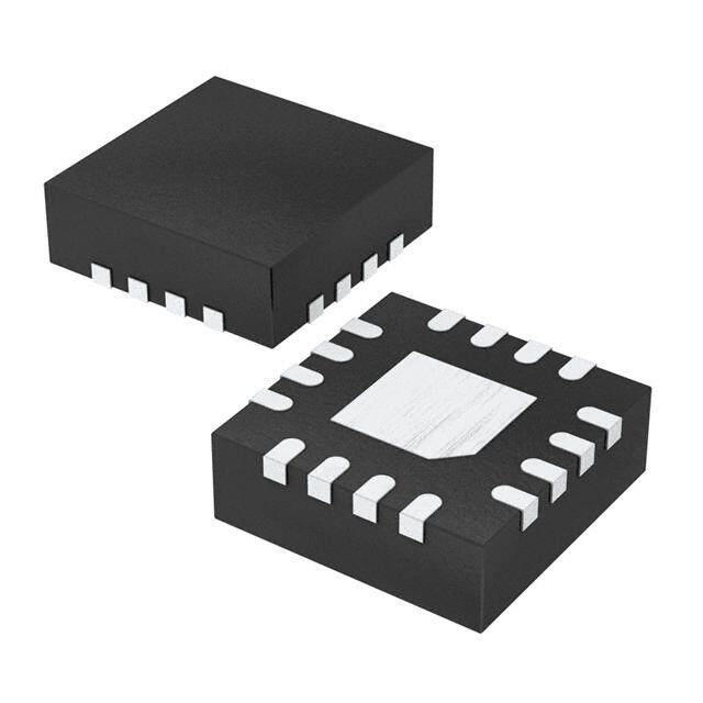
| 使用的IC/零件 | TPS62260/40/90 |
| 其它名称 | 296-23400 |
| 制造商产品页 | http://www.ti.com/general/docs/suppproductinfo.tsp?distId=10&orderablePartNumber=TPS62260LED-338 |
| 参考设计库 | http://www.digikey.com/rdl/4294959899/4294959881/715 |
| 商标 | Texas Instruments |
| 尺寸 | 110 mm x 61 mm |
| 工具用于评估 | TPS62260 |
| 工厂包装数量 | 1 |
| 所含物品 | 板 |
| 标准包装 | 1 |
| 特性 | RGB 控制 |
| 电压-输入 | 3.6 V ~ 6 V |
| 电压-输出 | - |
| 电流-输出/通道 | 600mA |
| 相关产品 | /product-detail/zh/TPS62260DDCT/296-22469-2-ND/1666627/product-detail/zh/TPS62260DRVT/296-22470-2-ND/1666628/product-detail/zh/TPS62261DRVT/296-22471-2-ND/1666629/product-detail/zh/TPS62262DRVT/296-22472-2-ND/1666630/product-detail/zh/TPS62260DDCT/296-22469-1-ND/1667038/product-detail/zh/TPS62260DRVT/296-22470-1-ND/1667039/product-detail/zh/TPS62261DRVT/296-22471-1-ND/1667040/product-detail/zh/TPS62262DRVT/296-22472-1-ND/1667041/product-detail/zh/TPS62260DRVT/296-22470-6-ND/1849471/product-detail/zh/TPS62260DDCR/TPS62260DDCR-ND/1908042/product-detail/zh/TPS62260DDCRG4/TPS62260DDCRG4-ND/1908043/product-detail/zh/TPS62260DDCTG4/TPS62260DDCTG4-ND/1908044/product-detail/zh/TPS62260DRVR/296-27029-2-ND/1908045/product-detail/zh/TPS62260DRVTG4/TPS62260DRVTG4-ND/1908047/product-detail/zh/TPS62261DRVRG4/TPS62261DRVRG4-ND/1908050/product-detail/zh/TPS62261DRVTG4/TPS62261DRVTG4-ND/1908051/product-detail/zh/TPS62262DRVR/TPS62262DRVR-ND/1908052/product-detail/zh/TPS62262DRVTG4/TPS62262DRVTG4-ND/1908054/product-detail/zh/TPS62260DDCT/296-22469-6-ND/1947112/product-detail/zh/TPS62261DRVT/296-22471-6-ND/1947113/product-detail/zh/TPS62262DRVT/296-22472-6-ND/1947114 |
| 类型 | Power Management Specialized |
| 输入电压 | 3.6 V to 6 V |
| 输出和类型 | 3,非隔离 |


- 商务部:美国ITC正式对集成电路等产品启动337调查
- 曝三星4nm工艺存在良率问题 高通将骁龙8 Gen1或转产台积电
- 太阳诱电将投资9.5亿元在常州建新厂生产MLCC 预计2023年完工
- 英特尔发布欧洲新工厂建设计划 深化IDM 2.0 战略
- 台积电先进制程称霸业界 有大客户加持明年业绩稳了
- 达到5530亿美元!SIA预计今年全球半导体销售额将创下新高
- 英特尔拟将自动驾驶子公司Mobileye上市 估值或超500亿美元
- 三星加码芯片和SET,合并消费电子和移动部门,撤换高东真等 CEO
- 三星电子宣布重大人事变动 还合并消费电子和移动部门
- 海关总署:前11个月进口集成电路产品价值2.52万亿元 增长14.8%


PDF Datasheet 数据手册内容提取
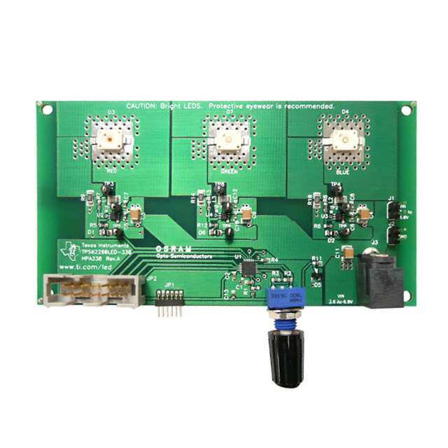
TPS62260LED-338 Three-Color LED Driver Evaluation Module (EVM) www.ti.com/led User's Guide LiteratureNumber:SLVU240B May2008–RevisedAugust2018
Contents Preface........................................................................................................................................ 4 1 Introduction......................................................................................................................... 6 1.1 Requirements ................................................................................................................ 6 1.1.1 PowerSupplyRequirements...................................................................................... 6 1.1.2 PrintedCircuitBoardAssemblies(PCBs)....................................................................... 6 2 Setup.................................................................................................................................. 7 2.1 Input/OutputConnectorDescriptions ..................................................................................... 7 2.1.1 J1,J2,andJ3–PowerSupplyConnectors .................................................................... 7 2.1.2 JP1–WirelessInterfaceConnector ............................................................................. 7 2.1.3 JP2–JTAGInterfaceConnector................................................................................. 7 2.2 HardwareSetup.............................................................................................................. 8 3 SupportedColorsandOperationModes................................................................................. 9 3.1 ColorRange ................................................................................................................. 9 3.2 Auto-ScrollMode ............................................................................................................ 9 3.3 ManualControlMode....................................................................................................... 9 4 DesignDescription............................................................................................................. 11 4.1 HardwareDesign .......................................................................................................... 11 4.1.1 LEDPowerStages ............................................................................................... 11 4.1.2 OutputFilterDesign............................................................................................... 12 4.1.3 MODEandENPins .............................................................................................. 12 4.1.4 MSP430MCUDesign............................................................................................ 12 4.2 LEDColorTable............................................................................................................ 13 4.3 FirmwareDesign........................................................................................................... 13 4.3.1 FirmwareC-CodeListing......................................................................................... 16 5 SchematicandBillofMaterials............................................................................................ 19 5.1 Schematics.................................................................................................................. 19 5.2 BillofMaterials............................................................................................................. 21 6 BoardLayout..................................................................................................................... 22 6.1 PhotographsofTopandBottom......................................................................................... 22 6.2 Layout........................................................................................................................ 23 6.3 ThermalImages............................................................................................................ 25 A Reprogramming................................................................................................................. 26 A.1 AdditionalSoftwareandHardwareNeeded............................................................................ 26 A.2 IAREmbeddedWorkbenchKickStartSoftwareInstallation.......................................................... 26 A.3 HardwareInstallation...................................................................................................... 26 A.4 UsingIAREmbeddedWorkbenchtoDownloadCodeonMSP430MCUs......................................... 27 RevisionHistory.......................................................................................................................... 28 2 Contents SLVU240B–May2008–RevisedAugust2018 SubmitDocumentationFeedback Copyright©2008–2018,TexasInstrumentsIncorporated
www.ti.com List of Figures 3-1. CIEChromaticityDiagram ................................................................................................ 10 6-1. HPA338TopView.......................................................................................................... 22 6-2. HPA338BottomView...................................................................................................... 23 6-3. PCBTopAssemblyLayer................................................................................................. 23 6-4. PCBLayerOne............................................................................................................. 24 6-5. PCBLayerTwo............................................................................................................. 24 6-6. EVMWithoutHeatsink..................................................................................................... 25 6-7. EVMWithHeatsink........................................................................................................ 25 List of Tables 5-1. BillofMaterials............................................................................................................. 21 SLVU240B–May2008–RevisedAugust2018 ListofFigures 3 SubmitDocumentationFeedback Copyright©2008–2018,TexasInstrumentsIncorporated
Preface SLVU240B–May2008–RevisedAugust2018 Read This First About This Manual Thisuser'sguidedescribesthecharacteristics,setup,anduseoftheTPS62260LED-338 three-colorlight- emittingdiode(LED)driverevaluationmodule(EVM).ThisEVMcontainsthreeTPS62260 2.25-MHz,600- mAstep-downvoltageconvertersandanMSP430F2131 microcontroller(MCU).EachTPS62260applies powertooneofthethreehighbrightnessLEDs(red,green,orblue).TheMSP430F2131controlsthe outputcurrentofthethreeconvertersindividually. How to Use This Manual Thisdocumentcontainsthefollowingsections: • Chapter1–Introduction • Chapter2–Setup • Chapter3–SupportedColorsandOperationModes • Chapter4–DesignDescription • Chapter5–SchematicandBillofMaterials • Chapter6–BoardLayout • AppendixA– Reprogramming ReadChapter2beforeconnectingtheboardtoapowersupplyforthefirsttime. Information About Cautions and Warnings Thisuser'sguidemaycontaincautionsandwarnings. CAUTION Thisisanexampleofacautionstatement. Acautionstatementdescribesasituationthatcouldpotentiallydamageyour softwareorequipment. WARNING This is an example of a warning statement. A warning statement describes a situation that could potentially cause harm to you. Theinformationinacautionorawarningisprovidedforyourprotection.Readeachcautionandwarning carefully. 4 ReadThisFirst SLVU240B–May2008–RevisedAugust2018 SubmitDocumentationFeedback Copyright©2008–2018,TexasInstrumentsIncorporated
www.ti.com RelatedDocumentationFromTexasInstruments Related Documentation From Texas Instruments TPS6226x2.25-MHz600-mAStepDownConverterin2x2WSONandSOTPackagedatasheet MSP430x2xxFamilyUser'sGuide MSP430F21x1Mixed-SignalMicrocontrollersdatasheet MSP430F2131DeviceErratasheet If You Need Assistance ContactyourlocalTIsalesrepresentativeoraskaquestionontheTIE2E™Communityforums. Trademarks E2E,MSP430aretrademarksofTexasInstruments. IAREmbeddedWorkbench,C-SPYareregisteredtrademarksofIARSystems. WindowsisaregisteredtrademarkofMicrosoftCorporation. Allothertrademarksarethepropertyoftheirrespectiveowners. SLVU240B–May2008–RevisedAugust2018 ReadThisFirst 5 SubmitDocumentationFeedback Copyright©2008–2018,TexasInstrumentsIncorporated
Chapter 1 SLVU240B–May2008–RevisedAugust2018 Introduction This TPS62260LED-338 EVM enables the user to individually control the brightness of three high- brightness LEDs. By adjusting the relative brightness of each of the three LEDs, the user can generate a widerangeofcolorsacrossthespectrum. The desired output color can be adjusted by means of a rotary encoder. Alternatively, the board can be leftinitsdefaultpower-upstate,inwhichitcontinuouslycyclesthroughthewholerangeofcolors. Formoredetailsontheoperationoftheboard,refertoChapter3. 1.1 Requirements TooperatethisEVM,ithastobesuppliedwithavoltagebetween3.6Vand6V.Thecurrentcapabilityof thepowersupplyshouldbe1Aorhigher.TheEVMkitcontainseverythingnecessarytooperatetheEVM excepttheDCpowersupply. ReprogrammingoftheMSP430F2131microcontrollercanbedonebyconnectingan MSP430™JTAG interfaceboard(forexample,theMSP-FETMSPMCUProgrammerandDebugger).ThisMSP430 developmenttoolisnotincludedintheTPS62260LED-338EVM. 1.1.1 Power Supply Requirements TheEVMrequiresaregulatedDCpowersupplythatcandeliver3.6Vto6Vat1A. CAUTION Use of a poorly regulated AC adapter may generate overvoltage conditions exceeding the absolute maximum ratings of some of the components used. It is recommended that only well-regulated (5 V ± 0.5 V) adapters be used with this EVM. CAUTION AC adapters with long cables (approximately 1 m or longer) can exhibit significant stray capacitance that may interact with the EVM input capacitance and cause ringing when hot plugged. To avoid such potentially damaging overvoltage conditions, first plug the adapter DC plug into J3, then connect the ACadaptertothemains. 1.1.2 Printed Circuit Board Assemblies (PCBs) TheEVMcomprisesasinglePCBfeaturingfourconnectors,withoneofthemdesignedtoaccommodate anoptionallow-powerwirelessinterface.ThewirelessinterfaceconnectionisnotpartofthisEVM.For moredetails,refertoSection2.1.2. 6 Introduction SLVU240B–May2008–RevisedAugust2018 SubmitDocumentationFeedback Copyright©2008–2018,TexasInstrumentsIncorporated
Chapter 2 SLVU240B–May2008–RevisedAugust2018 Setup This chapter explains the function of the connectors on the PCB as well as how to properly connect, set up,andusetheTPS62260LED-338EVM. 2.1 Input/Output Connector Descriptions 2.1.1 J1, J2, and J3 – Power Supply Connectors J1andJ2aretwo-pinheadersforeasyconnectionofalabpowersupply.Connectapositiveinputvoltage between3.6Vand6VtoJ1and0V(ground)toJ2.Thelabpowersupplycurrentlimithastobesettoat least1A. J3canbeconnectedwitha5-mm×2.5-mmbarrelconnectorofthetypecommonlyusedwithlow-costAC adapters.Theinnercontactispositive(5V)relativetotheoutercontact(GND).Possiblewalladapters couldbeEgstonP2CFSW3–5V/1.2A,5.0VDC,1.2Awithuniversalconnectorset(makesurethatthe orientationoftheconnectoriscorrect)orSLPowerElectronicsPW170KA05V/2Awiththerightcountry connector. 2.1.2 JP1 – Wireless Interface Connector TheJP1isapinheaderthatcanbeusedforplug-onoftheRFboardfromtheeZ430-RF2500kit,whichis separatelyavailable.Withthisadditionalmodule,thecolorsofthelampcanbecontrolledremotely throughthewirelessRFinterface. NOTE: ThefirmwareincludedinthestandardEVMdoesnotcurrentlysupportwirelessmodules. Userswhowishtousewirelessarerequiredtowritetheirown(simple)routines.Different softwarelibrariessupporttherealizationofstar-networksorpoint-to-pointwireless connectionsusingMSP430microcontrollers.TheselibrariesincludeSimpliciTi(starnetwork) orMSP430andCC2500codelibrary(point-to-pointconnection). NOTE: WhenthewirelessmoduleisconnectedtothestandardEVM,thepowerrequirement increases.Tosupportthishigherpowerrequirement,changeresistorR11toa080568-Ω resistor. 2.1.3 JP2 – JTAG Interface Connector TheJTAGconnectorJP2isusedastheprogramminginterfacefortheMSP430F2131microcontroller. OnlyMSP430JTAGprogrammingadaptors(liketheMSP-FETMSPMCUProgrammerandDebugger) canbeusedfortheprogramdownload.ThistoolalsoallowsdebuggingofanewMSP430software. TheconnectorontheTPS62260LED-338EVMusesstandardpinningalsousedonthedifferentMSP430 JTAGtools.ThismeansthatthecabledeliveredwithMSP-FETcanbepluggedintotheJP2connectorof theTPS62260LED-338EVM. NOTE: ProgramminganddebuggingwiththeMSP430JTAGinterfacetoolsworksonlyifthe TPS62260LED-338EVMissuppliedbya5-Vpowersupply. SLVU240B–May2008–RevisedAugust2018 Setup 7 SubmitDocumentationFeedback Copyright©2008–2018,TexasInstrumentsIncorporated
HardwareSetup www.ti.com TheMSP430JTAGprogrammingadaptorisnotpartofthispackagebutcanbeorderedfromtheTIStore. Forinstructionstosetuptheprogrammingadapterandupdatetheprogramalreadyinstalledonthe MSP430F2131,seeAppendixA. 2.2 Hardware Setup WARNING Turning on the power supply lights the high-brightness LEDs on the board, starting with blue and cycling automatically through the color range. Protective eyewear is recommended! Tosetupthehardware: • PlugtheDCconnectoroftheACadapterintoJ3orconnectalabpowersupplysetto3.6Vto6V betweenJ1andJ2. • PlugthemainsconnectoroftheACadapterintothemainssupply. • Turnonthemainssupply. CAUTION Use of a poorly regulated AC adapter may generate overvoltage conditions exceeding the absolute maximum ratings of some of the components used. It is recommended that only well-regulated (5 V ± 0.5 V) adapters be used with this EVM. CAUTION AC adapters with long cables (approximately 1 m or longer) can exhibit significant stray capacitance that may interact with the EVM input capacitance and cause ringing when hot plugged. To avoid such potentially damaging overvoltage conditions, first plug the adapter DC plug into J3, then connect the ACadaptertothemains. 8 Setup SLVU240B–May2008–RevisedAugust2018 SubmitDocumentationFeedback Copyright©2008–2018,TexasInstrumentsIncorporated
Chapter 3 SLVU240B–May2008–RevisedAugust2018 Supported Colors and Operation Modes This chapter explains the two control modes of the TPS62260LED-338 EVM. If the LEDs are controlled in a different way, specialized software can be downloaded through the JTAG connector JP2 to the MSP430F2131.Forthedownloadprocess,refertoAppendixA. 3.1 Color Range TheTPS62260LED-338EVMwiththedefaultsoftwaredoesnotsupporttheentirerangeofcolors describedbytheCIEchromaticitydiagram,butinsteadsupportsareducedsubset.Thisapproachgreatly reducesthedesigneffortwhilesimultaneouslyprovidingarangeofpossiblecolorsspanningthe spectrum.Figure3-1showstheCIEchromaticitydiagramrepresentingtherangeofpossiblecolors;the innertrianglerepresentsthereducedrangeofcolorssupportedbytheEVMwiththedefaultsoftware. WhentheEVMscrollsthroughitsrangeofcolors,iteffectivelytracestheedgesoftheinnertriangle showninFigure3-1.Ascanbeseenfromthistriangle,whentracingtheedgesclockwisethiscolor transitionsfrombluetogreen,throughyellowandorangetored,andthenfromredthroughpurplebackto blue. 3.2 Auto-Scroll Mode TheEVMpowersupinauto-scrollmodestartingwithblue.Inauto-scrollmodetheMSP430autonomously cyclesclockwisethroughtherangeofsupportedcolorsadinfinitum. Afterswitchingtomanualcontrolmodebyusingtherotaryencoder,auto-scrollmodecanbeenteredby poweringuptheboardagain. 3.3 Manual Control Mode TheEVMleavesauto-scrollmodeandentersmanualcontrolmodethefirsttimetherotarycontrolis activated.Inmanualcontrolmode,thecolorbalanceofthethreeLEDsisadjustedbytheuserturningthe rotaryencoderS1.Thefastertheencoderisturned,thefasterthecolorstransitionfromonetoanother; thedirectionofrotationdetermineswhethertheEVMtracesthecolortriangleinFigure3-1clockwiseor counterclockwise. SLVU240B–May2008–RevisedAugust2018 SupportedColorsandOperationModes 9 SubmitDocumentationFeedback Copyright©2008–2018,TexasInstrumentsIncorporated
ManualControlMode www.ti.com Figure3-1.CIEChromaticityDiagram 10 SupportedColorsandOperationModes SLVU240B–May2008–RevisedAugust2018 SubmitDocumentationFeedback Copyright©2008–2018,TexasInstrumentsIncorporated
Chapter 4 SLVU240B–May2008–RevisedAugust2018 Design Description This chapter describes the design steps to build the hardware and firmware for the TPS62260LED-338 EVM. This chapter includes the board description and the detailed instructions used in the firmware programloadedbydefaultontotheMSP430F2131. 4.1 Hardware Design Theschematicsandbillofmaterialsreferredtointhefollowingdesigndescriptionarecontainedin Chapter5.ThedesigncontainsthreeidenticalLEDdriverstages;onlyone(theredchannel)isdescribed. 4.1.1 LED Power Stages BecausethebrightnessofanLEDisdeterminedbythecurrentflowingthroughit,notthevoltageacross it,LEDstendtobepoweredbycurrentsourcesinallthesimplestofapplications(thatis,whenuniform intensityandcolorbalancearenotimportant).Inthisapplication,eachpowerstageusesaTPS62260 DC/DCconverterconfiguredasacontrollablecurrentsource.Insteadofusingaresistordividerbetween theoutputandGNDtogeneratethefeedbackvoltage,asmallcurrent-sensingresistorisinserted betweentheLEDcathodeandGND.Inthisconfiguration,theTPS62260controlsitsdutycycleat whatevervalueisneededtoregulatethevoltageacrossthecurrent-sensingresistorto0.6V(theinternal referencevoltageoftheIC).Usinga2-Ω current-sensingresistor,theLEDcurrentisthereforeregulated toavaluegivenby: V 0.6V FB I = = = 300 mA LED RSNS 2Ω (1) BrightnessisvariedbypulsewidthmodulatingthecurrentflowingthrougheachLED.Thisapproachhas twomainadvantagescomparedwithusinganalogmethodstocontrolLEDcurrent. First,thecolorbalanceofanLEDchangeswiththecurrentflowingthroughit,sonotonlyisthebrightness ofanLEDat10mAdifferentthanat100mA,itscoloris,too.Withpulsewidthmodulation(PWM) dimming,thecurrentflowingthroughtheLEDwhenitisactiveisalwaysthesamesoitscolordoesnot change.Aslongasthedimmingfrequencyishighenough,theonlyeffectthehumaneyeseesisa variationinLEDintensity.Inthisapplication,anominaldimmingfrequencyof122Hzisused. Second,itissimplerandcheapertogeneratethreePWMsignalsusingamicrocontrollerthanthree analogvoltages,whichwouldrequirea3-channelDAC. ThePWMdimmingschemeworksasfollows: • WhentheNET_DIMM_LED1signalislow,D1blocksanycurrentflowawayfromtheFBpinandU2 regulatesLEDcurrenttoitsfull-scalevalueof300mA(seeEquation1). • WhenNET-DIMM_LED1ishigh(closetothe3.3-VsupplyvoltageofU2)theU2FBpinisheldat 1.35V,whichforcesthedutycycleofU2andconsequentlytheLEDcurrenttozero(seeEquation2). SLVU240B–May2008–RevisedAugust2018 DesignDescription 11 SubmitDocumentationFeedback Copyright©2008–2018,TexasInstrumentsIncorporated
HardwareDesign www.ti.com R 7 V =V + (V –V –V )X FB R9 CC D1 R9 R + R 7 5 10 kΩ V =V + (3.3V– 0.6V–V )X FB R9 R9 10 kΩ+10 kΩ 2.7V VR9 V =V +(V – FB R9 CC 2 2 V R9 V =V + 1.35V FB R 1 2 (2) TheaveragecurrentflowingthroughtheLEDanditsbrightnessaresimplytheproductsofthefull-scale (FS)LEDcurrentmultipliedbythedutycycleofthedimmingsignal(NET_DIMM_LED1): ILED(AVG)=ILED(FS)XDNET_DIMM_LED1 ILED(AVG)= 300 mAXDNET_DIMM_LED1 (3) 4.1.2 Output Filter Design TheTPS62260datasheetstatesthatthepartisoptimizedforusewithanoutputfiltercomprisinga 2.2‑µHinductoranda10-µFcapacitor.Inthisapplication,thestandardinductorvaluewasused.However, becauseoutputvoltagerippleisuncritical(at2.5MHzthehumaneyedetectsnoworseningof performance)asmallercapacitorvalueof4.7µFwasusedtoreducecost. 4.1.3 MODE and EN Pins TheTPS62260featuresapower-savemodetoimproveefficiencyatlowoutputpowers,butitisnot neededinthisapplication.ByconnectingtheU2MODEpintoVIN,thisfeatureisdisabled,andthedevice operatespermanentlyinPWMmode. AllthreeLEDdrivercircuitsareconnectedtoacommonenablesignal(NET_EN)thatallowstheMSP430 MCUtocompletelyenableanddisablethepowerstagesifnecessary.Apulldownresistorisusedforthe TPS62260enablesignal.ThispulldownresistorcausesallLEDstoswitchoffafterthesupplyvoltageis appliedtotheEVM.TheMSP430MCUactivatestheLEDsandavoidflashingLEDsduringstartup. 4.1.4 MSP430 MCU Design TheMSP430MCUispoweredthroughasimple(andinexpensive)3.3-VZenerdiodelinearregulator. ResistorR11setstheD5biascurrenttoapproximately5mA,whichissignificantlymorethanthecurrent drawnbytheMSP430.Thismaintainsgoodregulationinthefaceofchangingloadcurrents.Becausethe inputsupplytotheboardisregulatedto5V,theZenerregulatorcircuitexperiencesalmostnoinput voltagevariation. TherotaryencoderS1allowsmanualcontrolofthecolorinterfacesofthelamptotheMSP430MCU usingtwodigitalinputpins.Whenrotated,thistypeofencodergeneratestwopulsetrains90degreesout ofphase.Thenumberofturnscanbedeterminedbycountingthenumberofpulsesgenerated,the directionofrotationcanbedeterminedbycomparingtherelativephaseofthetwosignals,andthespeed ofrotationcanbedeterminedbymeasuringthefrequencyofthepulses.Thiscanbeeasilyachieved usingoneofthebuilt-intimersoftheMSP430MCU. R4holdsthethreeLEDpowerstagesinadisabledstateuntiltheMSP430haspoweredupandisready toassumecontrol.R1andC1provideapower-upresetfortheMSP430.JP2providesaJTAGinterface toalloweasydebuggingandJP1providestheconnectionstotheoptionallow-powerwirelessinterface. 12 DesignDescription SLVU240B–May2008–RevisedAugust2018 SubmitDocumentationFeedback Copyright©2008–2018,TexasInstrumentsIncorporated
www.ti.com LEDColorTable 4.2 LED Color Table ToobtainthecorrectopticalresponsefromtheLEDs,theirrelativebrightness(thatis,thecurrentflowing throughthem)isnotvariedlinearly,butisvariedaccordingtoalookuptablederivedfromtheCIE chromaticitydiagram.ThislookuptableisstoredintheflashmemoryoftheMSP430MCUanddefinesthe edgesoftheinnertriangleshowninFigure3-1,whichtheEVMtraces.ThestandardEVMlookuptable contains252locations,eachofwhichcontainsthecorrectvalueforthered,green,andblueLEDPWM signals. 4.3 Firmware Design ThissectiondetailsthefunctionofthedefaultsoftwareloadedontotheMSP430F2131.Becausethecolor schemeissetthroughintegervaluesgiveninthreeLEDcolorarrays,nosoftwarechangeisneededfor changingthecolorscheme.ChangingthevaluesintheLEDx[]arrayschangesthecolors. #include "msp430x21x1.h" AllperipheralcontrolregistersandcontrolbitsoftheMSP430F2131aredefinedintheheaderfile msp430x21x1.h. #define LED_TabLength 252*4 HerethelengthofthearraysLED1[],LED2[],andLED3[]isdefined.Itisusedtodetecttheoverflowof theLEDptr.CareshouldbetakenthatallthreearraysLED1[],LED2[],andLED3[]havethelengththat isdefinedhere. const unsigned int LED1[]={65385,65385,65385, ¼,65385,65385}; //blue LED const unsigned int LED2[]={ 150, 295, 622, ¼, 150, 150}; //green LED const unsigned int LED3[]={ 150, 150, 150, ¼, 311, 150}; //red LED ThethreearraysareusedforthePWMdutycycleadjustment.ForeachLED(red,green,andblue)there isanownarray.Butthereisonlyonepointer(LEDptr)thatisusedtofindthePWMsettingsforeachof thearrays.Thevaluesofthearrayshouldbewithintherange100to65535. unsigned int LEDptr; ThisisthevariableusedasthepointerforthethreearraysLED1[],LED2[],andLED3[]. unsigned char BAold; Thisvariableisusedforthedetectionofachangeoftheincrementalencoder. void main(void) { unsigned int i,temp; WDTCTL=WDTPW+WDTHOLD; // disable Watchdog The Watchdog is not used in this program. So it is disabled. BCSCTL1= CALBC1_8MHZ; //--- System Clock Settings ---------------------- DCOCTL = CALDCO_8MHZ; // use calibrated 8MHz settings TheWatchdogisnotusedinthisprogram.BysettingthecontrolbitWDTHOLDincontrolregister WDTCTLtheWatchdogisdisabled. BCSCTL1= CALBC1_8MHZ; //--- System Clock Settings ---------------------- DCOCTL = CALDCO_8MHZ; // use calibrated 8MHz settings TherearecalibrationvaluesavailableintheflashmemoryoftheMSP430MCU.Thesetwocommands movethecalibrationvaluefor8-MHzDCOoutputfrequencyintotheclocksystemcontrolregisters. //---- PWM Timer Initialization ------------------ TACTL = TASSEL_2+ID_0+MC_0+TACLR+TAIE; // Timer clock = SMCLK = 8MHz TACCTL0 = CM_0+CCIS_2+OUTMOD_1; // All Output Units will set PWM outputs if TACCTL1 = CM_0+CCIS_2+OUTMOD_1; // TACCRx=TAR. Resetting PWM outputs is done TACCTL2 = CM_0+CCIS_2+OUTMOD_1; // by software. TheTimer_Amoduleisinitializedhere.Itusesthecalibrated8-MHzDCOclocksignal.Atimeroverflow generatesaninterrupt.ThethreecaptureandcompareblocksCCR0,CCR1,andCCR2areusedin comparemode.TheoutputunitofeachCCRblockisusedtogenerateaPWMsignal.Theoutputunits areautomaticallysettingthePWMoutput,whiletheresettingoftheoutputsignalisdonebysoftwareas soonasatimeroverflow(Timer_Ainterrupt)happens. LEDptr=0; TACCR0=LED1[LEDptr>>2]; // LEDptr is shifted right twice, SLVU240B–May2008–RevisedAugust2018 DesignDescription 13 SubmitDocumentationFeedback Copyright©2008–2018,TexasInstrumentsIncorporated
FirmwareDesign www.ti.com TACCR1=LED2[LEDptr>>2]; // this means divided by 4 TACCR2=LED3[LEDptr>>2]; LEDptriscleared.ThismeansthefirstvaluesofthearraysLED1[],LED2[],andLED3[]areusedatthe beginning.WhenLEDptrisusedforthearray,itisdividedby4(shiftingLEDptrtwotimesrightisthe sameasdividedby4).Thisisdonetoavoidissueswiththebouncingoftheincrementalencoder. //--- Port Initialization ---------------------------------- P1SEL = 0x0E; // P1.1, P1.2, P1.3 are used as PWM Timer Outputs P1OUT = 0x00; // P1.0 is output (Enable for TPS62260) P1DIR = 0xFF; // P1.4, P1.5, P1.6, P1.7 are not used => digital outputs P2OUT = 0x04; // P2.0 and P2.1 are not used => digital outputs P2DIR|= 0xE4; // P2.3, P2.4 are digital inputs => incremental encoder // P2.5, P2.6, P2.7 are not used => digital outputs InitializationofthedigitalI/Os.P1.1,P1.2,andP1.3areusedasTimer_APWMoutput(modulefunction). Allpinsthatarenotusedaredefinedasdigitaloutputs. BAold=0x01; //--- initialize decoder for incremental encoder ----------- Initializationofthevariableusedforincrementalencoderdetection. Delay(); // Delay loop TACTL |= MC_2; // start Timer_A (continuous mode) AfterashortdelaylooptheTimer_Aisstarted.TheTimer_Aisusedincontinuousmode,thismeansit countsfrom0to65535.Ifthecounteris65535andthetimergetsanotherclockthecountervalueissetto 0andanoverflowinterruptisgenerated. __enable_interrupt(); // enables maskable interrupts Allmaskableinterruptsareenabled.Nowtheinterruptserviceroutinesarecalledifthereisaninterrupt event. temp=P2IN&0x18; //--- Main Loops --------------------------------------------------------------- while ((P2IN&0x18)==temp) //--- change settings automatically till Thisisthefirstoperatingmodeoftheapplication.ItstaysinthisloopaslongaspinsP2.3andP2.4donot change(thismeansaslongastheincrementalencoderS1wasnotused). { Delay(); // incremental encoder is operated LEDptr=LEDptr+1; if (LEDptr>=LED_TabLength) LEDptr=0; } ThefirstoperatingmodeoftheapplicationautomaticallychangestheLEDptr.Thisisdonebyusinga simpledelayloopandafterwardstheLEDptrisincremented.AfterincrementingtheLEDptritischeckedif themaximumtablelengthisreached.IfthisisthecasetheLEDptrisreset. while(1) //--- change settings manually (incremental encoder) { Inc_Decoder(0x03&(P2IN>>3)); // check incremental decoder for(i=0;i<=1000;i++); // delay loop (used for debouncing) } WhentheincrementalencoderS1isturned,thisloopisexecuted.Thisisanentireloop.Herethe incrementalencoderischecked.Afterwards,thereisashortdelayloopthatisusedfordebouncingofthe incrementalencoder. } //------------------------------------------------------------------------------ // Delay Loop void Delay(void) { unsigned int i,j; for(i=0;i<=10000;i++) // delay loop for(j=0;j<=3;j++); } Thisisthedelayloopthatismainlyusedfortheautomaticmode.Itdefinesthetimethesinglesettingsof thearraysareusedbeforethenextoneismovedtotheTimer_Acontrolregisters. //------------------------------------------------------------------------------ 14 DesignDescription SLVU240B–May2008–RevisedAugust2018 SubmitDocumentationFeedback Copyright©2008–2018,TexasInstrumentsIncorporated
www.ti.com FirmwareDesign // Incremental Encoder Subroutine: void Inc_Decoder(unsigned char BAnew) { if (BAnew==0x02) { if (BAold==0x00) { LEDptr=LEDptr-1; // decrement pointer if new state is 'b' and if (LEDptr>=LED_TabLength) // old state was 'a' LEDptr=LED_TabLength; } } if (BAnew==0x00) { if (BAold==0x02) { LEDptr=LEDptr+1; // increment pointer if new state is 'a' and if (LEDptr>=LED_TabLength) // old state was 'b' LEDptr=0; } } BAold=BAnew; // store new state } Theincrementalencodergeneratesagraycode.Fromthefourdifferentstatestheprogramistestingfor onlytwostates.ThetwostatesareP2.3='0',P2.4='0'andP2.3='1',P2.4='0'.Incrementing/decrementingof LEDptrisonlydoneifthestatethatwasreadduringthepreviousexecutionoftheInc_Decoder()function (thiswasstoredinBAold)isdifferent. //------------------------------------------------------------------------------ // Timer_A Interrupt Service Routine: #pragma vector=TIMERA1_VECTOR __interrupt void ISR_TimerA(void) { P1OUT |= 0x01; // activate LEDs ThisistheTimer_Ainterruptserviceroutine.ItiscalledassoonasthereisaTimer_Aoverflow.Thefirst instructionissettingtheP1.0pin.ThisenablestheDC/DCconverters. //--- update PWM duty cycle settings using color table TACCR0=LED1[LEDptr>>2]; // LEDptr is shifted right twice, TACCR1=LED2[LEDptr>>2]; // this means divided by 4 TACCR2=LED3[LEDptr>>2]; ThesettingsforthePWMdutycyclesarereadfromthethreeLEDarrays.Thisisdoneintheinterrupt serviceroutinetoensurethatitissynchronizedwiththetimer.Ifthiswouldbedoneinthemainloop,the LEDwouldflickerincaseofachange. ThePWMsignalisgeneratedfromtheTimerCaptureandCompareBlock,thatis,adigitalcomparator comparestheControlRegister(TACCRx)withtheactualtimervalue.Arebothvaluesidentical,thePWM outputisset.TheresetofthePWMoutputhastobedonebysoftware.Thisisdonewithaninterrupt whenthereisatimeroverflowanditsInterruptServiceRoutineupdatestheTACCRsregisterif necessary. Ifthisisdoneinthemainloop,theupdatecouldhappenasynchronoustothetimer.Thenitcouldhappen thatforonePWMcyclethePWMsignalbecomesinvertedandtheLEDflickers. //--- PWM signal generation TACTL &= ~TAIFG; TACCTL0 &= ~OUTMOD_7; // OUTMOD_0 => PWM output=L TACCTL0 |= OUTMOD_1; // OUTMOD_1 => set PWM output TA0 as soon as TACCR0=TAR TACCTL1 &= ~OUTMOD_7; // OUTMOD_0 => PWM output=L TACCTL1 |= OUTMOD_1; // OUTMOD_1 => set PWM output TA1 as soon as TACCR1=TAR TACCTL2 &= ~OUTMOD_7; // OUTMOD_0 => PWM output=L TACCTL2 |= OUTMOD_1; // OUTMOD_1 => set PWM output TA2 as soon as TACCR2=TAR // TAR = Timer_A counter } FinallytheTimer_Ainterruptflagisclearedandalloutputsignalsarereset.TheTimerCCRblocksare usedtosettheTAxoutputsignals.ResettingtheTAxoutputshastobedonebysoftware.Thatisdone here. SLVU240B–May2008–RevisedAugust2018 DesignDescription 15 SubmitDocumentationFeedback Copyright©2008–2018,TexasInstrumentsIncorporated
FirmwareDesign www.ti.com 4.3.1 Firmware C-Code Listing AcompletelistingofthefirmwareusedintheEVMiscontainedbelow: /******************************************************************************/ /* RGB-LED Demo using MSP430F2131 and TPS62260 from Texas Instruments */ /* */ /* Description: */ /* Timer_A3 is used to generate 3 PWM signals. Timer overflow generates an */ /* interrupt and in its interrupt service routine the PWM outputs are */ /* reseted. Output Units will set the PWM outputs. */ /* Software starts in a demo mode that automatically changes the PWM */ /* settings. As soon as the incremental encoder is operated the automatic */ /* mode stops and the adjustment of the colour can be done manually. */ /*----------------------------------------------------------------------------*/ /* Texas Instruments Deutschland GmbH */ /* Christian Hernitscheck, November 2007 */ /******************************************************************************/ #include "msp430x21x1.h" #define LED_TabLength 252*4 const unsigned int LED1[]={65385,65385,65385,65385,65385,65385,65385,65385, 65385,65385,65385,65385,65385,65385,65385,65385,65385,65385,65385,65385,65385, 65385,65385,65385,65385,65385,65385,65385,65385,65385,65385,65385,65385,65385, 65385,65385,65385,65385,65385,65385,65385,65385,65385,65385,57866,52635,47404, 42173,36943,34327,31712,29096,26481,23866,21250,19942,18635,17327,16019,14712, 13404,12096,10789, 9481, 8173, 7519, 6865, 6212, 5558, 4904, 4577, 4250, 3923, 3596, 3269, 2942, 2615, 2288, 1962, 1635, 1308, 981, 654, 327, 150, 150, 150, 150, 150, 150, 150, 150, 150, 150, 150, 150, 150, 150, 150, 150, 150, 150, 150, 150, 150, 150, 150, 150, 150, 150, 150, 150, 150, 150, 150, 150, 150, 150, 150, 150, 150, 150, 150, 150, 150, 150, 150, 150, 150, 150, 150, 150, 150, 150, 150, 150, 150, 150, 150, 150, 150, 150, 150, 150, 150, 150, 150, 150, 150, 150, 150, 150, 150, 150, 150, 150, 150, 150, 150, 150, 150, 150, 150, 150, 150, 150, 150, 150, 150, 327, 654, 981, 1308, 1635, 1962, 2288, 2615, 2942, 3269, 3596, 3923, 4250, 4577, 4904, 5558, 6212, 6865, 7519, 8173, 9481, 10789,12096,13404,14712,16019,17327,18635,19942,21250,23866,26481,29096,31712, 34327,36943,39558,42173,44789,47404,52635,57866,65385,65385,65385,65385,65385, 65385,65385,65385,65385,65385,65385,65385,65385,65385,65385,65385,65385,65385, 65385,65385,65385,65385,65385,65385,65385,65385,65385,65385,65385,65385,65385, 65385,65385,65385,65385,65385,65385,65385,65385,65385,65385,65385}; //blue LED const unsigned int LED2[]={ 150, 295, 622, 949, 1276, 1603, 1930, 2256, 2583, 2910, 3237, 3564, 3891, 4218, 4545, 4872, 5526, 6180, 6833, 7487, 8141, 9449,10757,12064,13372,14680,15987,17295,18603,19910,21218,23834,26449,29064, 31680,34295,36911,39526,42141,44757,47372,52603,57834,65353,65353,65353,65353, 65353,65353,65353,65353,65353,65353,65353,65353,65353,65353,65353,65353,65353, 65353,65353,65353,65353,65353,65353,65353,65353,65353,65353,65353,65353,65353, 65353,65353,65353,65353,65353,65353,65353,65353,65353,65353,65353,65353,65353, 65353,65353,65353,65353,65353,65353,65353,65353,65353,65353,65353,65353,65353, 65353,65353,65353,65353,65353,65353,65353,65353,65353,65353,65353,65353,65353, 65353,65353,65353,65353,65353,65353,65353,65353,65353,65353,65353,65353,65353, 65353,65353,65353,57834,52603,47372,42141,36911,34295,31680,29064,26449,23834, 21218,19910,18603,17295,15987,14680,13372,12064,10757, 9449, 8141, 7487, 6833, 6180, 5526, 4872, 4545, 4218, 3891, 3564, 3237, 2910, 2583, 2256, 1930, 1603, 1276, 949, 622, 295, 150, 150, 150, 150, 150, 150, 150, 150, 150, 150, 150, 150, 150, 150, 150, 150, 150, 150, 150, 150, 150, 150, 150, 150, 150, 150, 150, 150, 150, 150, 150, 150, 150, 150, 150, 150, 150, 150, 150, 150, 150, 150, 150, 150, 150, 150, 150, 150, 150, 150, 150, 150, 150, 150, 150, 150, 150, 150, 150, 150, 150, 150, 150, 150, 150, 150, 150, 150, 150, 150, 150, 150, 150, 150, 150, 150, 150, 150, 150, 150, 150, 150, 150, 150, 150}; //green LED const unsigned int LED3[]={ 150, 150, 150, 150, 150, 150, 150, 150, 150, 150, 150, 150, 150, 150, 150, 150, 150, 150, 150, 150, 150, 150, 150, 150, 150, 150, 150, 150, 150, 150, 150, 150, 150, 150, 150, 150, 150, 150, 150, 150, 150, 150, 150, 150, 150, 150, 150, 16 DesignDescription SLVU240B–May2008–RevisedAugust2018 SubmitDocumentationFeedback Copyright©2008–2018,TexasInstrumentsIncorporated
www.ti.com FirmwareDesign 150, 150, 150, 150, 150, 150, 150, 150, 150, 150, 150, 150, 150, 150, 150, 150, 150, 150, 150, 150, 150, 150, 150, 150, 150, 150, 150, 150, 150, 150, 150, 150, 150, 150, 150, 150, 150, 150, 311, 638, 965, 1292, 1619, 1946, 2272, 2599, 2926, 3253, 3580, 3907, 4234, 4561, 4888, 5542, 6196, 6849, 7503, 8157, 9465,10773,12080,13388,14696,16003,17311, 18619,19926,21234,23850,26465,29080,31696,34311,36927,39542,42157,44773,47388, 52619,57850,65369,65369,65369,65369,65369,65369,65369,65369,65369,65369,65369, 65369,65369,65369,65369,65369,65369,65369,65369,65369,65369,65369,65369,65369, 65369,65369,65369,65369,65369,65369,65369,65369,65369,65369,65369,65369,65369, 65369,65369,65369,65369,65369,65369,65369,65369,65369,65369,65369,65369,65369, 65369,65369,65369,65369,65369,65369,65369,65369,65369,65369,65369,65369,65369, 65369,65369,65369,65369,65369,65369,65369,65369,65369,65369,65369,65369,65369, 65369,65369,65369,65369,65369,65369,65369,65369,65369,57850,52619,47388,42157, 36927,34311,31696,29080,26465,23850,21234,19926,18619,17311,16003,14696,13388, 12080,10773, 9465, 8157, 7503, 6849, 6196, 5542, 4888, 4561, 4234, 3907, 3580, 3253, 2926, 2599, 2272, 1946, 1619, 1292, 965, 638, 311, 150}; //red LED unsigned int LEDptr; unsigned char BAold; void Inc_Decoder(unsigned char BAnew); void Delay(void); //------------------------------------------------------------------------------ // Main Program void main(void) { unsigned int i,temp; WDTCTL=WDTPW+WDTHOLD; // disable Watchdog BCSCTL1= CALBC1_8MHZ; //--- System Clock Settings ---------------------- DCOCTL = CALDCO_8MHZ; // use calibrated 8MHz settings //---- PWM Timer Initialization ------------------ TACTL = TASSEL_2+ID_0+MC_0+TACLR+TAIE; // Timer clock = SMCLK = 8MHz TACCTL0 = CM_0+CCIS_2+OUTMOD_1; // All Output Units will set PWM outputs if TACCTL1 = CM_0+CCIS_2+OUTMOD_1; // TACCRx=TAR. Resetting PWM outputs is done TACCTL2 = CM_0+CCIS_2+OUTMOD_1; // by software. LEDptr=0; TACCR0=LED1[LEDptr>>2]; // LEDptr is shifted right twice, TACCR1=LED2[LEDptr>>2]; // this means divided by 4 TACCR2=LED3[LEDptr>>2]; //--- Port Initialization ---------------------------------- P1SEL = 0x0E; // P1.1, P1.2, P1.3 are used as PWM Timer Outputs P1OUT = 0x00; // P1.0 is output (Enable for TPS62260) P1DIR = 0xFF; // P1.4, P1.5, P1.6, P1.7 are not used => digital outputs P2OUT = 0x04; // P2.0 and P2.1 are not used => digital outputs P2DIR|= 0xE4; // P2.3, P2.4 are digital inputs => incremental encoder // P2.5, P2.6, P2.7 are not used => digital inputs BAold=0x01; //--- initialize decoder for incremental encoder ----------- Delay(); // Delay loop TACTL |= MC_2; // start Timer_A (continuous mode) __enable_interrupt(); // enables maskable interrupts temp=P2IN&0x18; //--- Main Loops --------------------------------------------------------------- while ((P2IN&0x18)==temp) //--- change settings automatically till { Delay(); // incremental encoder is operated LEDptr=LEDptr+1; SLVU240B–May2008–RevisedAugust2018 DesignDescription 17 SubmitDocumentationFeedback Copyright©2008–2018,TexasInstrumentsIncorporated
FirmwareDesign www.ti.com if (LEDptr>=LED_TabLength) LEDptr=0; } while(1) //--- change settings manually (incremental encoder) { Inc_Decoder(0x03&(P2IN>>3)); // check incremental decoder for(i=0;i<=1000;i++); // delay loop (used for debouncing) } } //------------------------------------------------------------------------------ // Delay Loop void Delay(void) { unsigned int i,j; for(i=0;i<=10000;i++) // delay loop for(j=0;j<=3;j++); } //------------------------------------------------------------------------------ // Incremental Encoder Subroutine: void Inc_Decoder(unsigned char BAnew) { if (BAnew==0x02) { if (BAold==0x00) { LEDptr=LEDptr-1; // decrement pointer if new state is 'b' and if (LEDptr>=LED_TabLength) // old state was 'a' LEDptr=LED_TabLength; } } if (BAnew==0x00) { if (BAold==0x02) { LEDptr=LEDptr+1; // increment pointer if new state is 'a' and if (LEDptr>=LED_TabLength) // old state was 'b' LEDptr=0; } } BAold=BAnew; // store new state } //------------------------------------------------------------------------------ // Timer_A Interrupt Service Routine: #pragma vector=TIMERA1_VECTOR __interrupt void ISR_TimerA(void) { P1OUT |= 0x01; // activate LEDs //--- update PWM duty cycle settings using colour table TACCR0=LED1[LEDptr>>2]; // LEDptr is shifted right twice, TACCR1=LED2[LEDptr>>2]; // this means divided by 4 TACCR2=LED3[LEDptr>>2]; //--- PWM signal generation TACTL &= ~TAIFG; TACCTL0 &= ~OUTMOD_7; // OUTMOD_0 => PWM output=L TACCTL0 |= OUTMOD_1; // OUTMOD_1 => set PWM output TA0 as soon as TACCR0=TAR TACCTL1 &= ~OUTMOD_7; // OUTMOD_0 => PWM output=L TACCTL1 |= OUTMOD_1; // OUTMOD_1 => set PWM output TA1 as soon as TACCR1=TAR TACCTL2 &= ~OUTMOD_7; // OUTMOD_0 => PWM output=L TACCTL2 |= OUTMOD_1; // OUTMOD_1 => set PWM otuput TA2 as soon as TACCR2=TAR // TAR = Timer_A counter } 18 DesignDescription SLVU240B–May2008–RevisedAugust2018 SubmitDocumentationFeedback Copyright©2008–2018,TexasInstrumentsIncorporated
Chapter 5 SLVU240B–May2008–RevisedAugust2018 Schematic and Bill of Materials ThischapterprovidestheTPS62260LED-338schematicsandbillofmaterials. 5.1 Schematics SLVU240B–May2008–RevisedAugust2018 SchematicandBillofMaterials 19 SubmitDocumentationFeedback Copyright©2008–2018,TexasInstrumentsIncorporated
Schematics www.ti.com 20 SchematicandBillofMaterials SLVU240B–May2008–RevisedAugust2018 SubmitDocumentationFeedback Copyright©2008–2018,TexasInstrumentsIncorporated
www.ti.com BillofMaterials 5.2 Bill of Materials Table5-1.BillofMaterials(1) (2) (3) COUNT RefDes(4) VALUE DESCRIPTION SIZE PARTNO. MANUFACTURER 1 C1 10nF Capacitor,Ceramic,50V, 0603 std std X5R,20% 1 C2 100nF Capacitor,Ceramic,50V, 0603 std std X5R,20% 4 C3,C4,C9, 22uF Capacitor,Ceramic,16V, 1210 C1210C226M4PAC KEMET C11 X5R,20% 7 C5-C8,C10, 4.7uF Capacitor,Ceramic,6.3V, 0603 C0603C475M9PAC KEMET C12,C13 X5R,20% 3 D1,D2,D6 TS4148RY Diode,Hi-Speed,150mA,100V,500mW 0805 TS4148RY Taiwan Semiconductor 1 D3 LRW5SM Diode,LEDRed,500-mA 0.244×0.441inch LRW5SM-HYJY-1-0-400-R18- Osram Z 1 D4 LBW5SM Diode,LEDBlue,500-mA 0.244×0.441inch LBW5SM-EYGX-35-0-350- Osram R18-Z 1 D5 BZX84-C3V3 Diode,Zener,3.3V,250mW,5% SOT23 BZX84-C3V3 NXP Semiconductor 1 D7 LTW5SM Diode,LEDGreen,500-mA 0.244×0.441inch LTW5SM-HYJZ-25-0-350- Osram R18-Z 2 J1,J2 PTC36SAAN Header,Male2-pin,100milspacing,(36- 0.100inch×2 PTC36SAAN Sullins pinstrip) 1 J3 RAPC712 Connector,Pindia.2.5mm,DCJack, 0.57×0.35inch RAPC712 Switchcraft 1 JP1 850-106-10-S-RA Header,1x6-pin,50milspacing 1.000×0.085inch 850-10-006-20-001000 Millmax 1 JP2 2514-6002UB Connector,MaleStraight2x7pin,100mil 0.100inch×2X7 2514-6002UB 3M spacing,4Wall 3 L1,L2,L3 2.2uH Inductor,SMT,2.2uH,1.1A,110-milliohm 2.5×2.0mm MIPSA2520D2R2LQM2HPN2 FDKmuRata orAlternateInductor;SMT,2.2uH,1.0A, 2.5×2.0×1.2mm R2MJ0L 120-milliohm 1 R1 47.0k Resistor,Chip,1/16W,1% 0603 Std Std 1 R11 330 Resistor,Chip,1/16W,1% 0603 Std Std 3 R2,R3,R4 100k Resistor,Chip,1/16W,1% 0603 Std Std 6 R5-R8,R12, 10.0k Resistor,Chip,1/16W,1% 0603 Std Std R13 3 R9,R10,R14 2.00 Resistor,Chip,1/8W,1% 1206 Std Std 1 S1 3315C-001 Encoder,SealedIncremental,9mm 0.375×0.400inch 3315C-001 Bourns Square 9 TP1-TP9 5001 TestPoint,Black,ThruHoleColorKeyed 0.100×0.100inch 5001 Keystone 1 U1 MSP430F2131TRGE IC,MixedSignalMicrocontroller QFN-24 MSP430F2131TRGE TI 3 U2,U3,U4 TPS62260DRV IC,2.25MHz600mAStep-Down SON-6[DRV] TPS62260DRV TI Converter 1 -- PCB,4.33Inx2.4Inx0.062In HPA338Rev.A Any 1 -- 020-2220(5) Knob,colletlocking,blackplastic 10mmoveralldia. "020-2220orequivalent" ELMA 1/8"shaftdia. 1 -- 040-1020(6) Cap,blackplastic 10mmoveralldia. 040-1020orequivalent ELMA (1) TheseassembliesareESDsensitive;ESDprecautionsshallbeobserved. (2) Theseassembliesmustbecleanandfreefromfluxandallcontaminants.Useofcleanfluxisrequired. (3) TheseassembliesmustcomplywithworkmanshipstandardsIPC-A-610Class2. (4) Referencedesignatorsmarkedwithanasterisk('**')cannotbesubstituted.Allothercomponentscanbesubstitutedwith equivalentcomponentsfromothermanufacturers. (5) Knob020-2220shallbeinstalledontoS1afterfinalboardassembly (6) Cap040-1020shallbeinstalledontoKnob020-2220 SLVU240B–May2008–RevisedAugust2018 SchematicandBillofMaterials 21 SubmitDocumentationFeedback Copyright©2008–2018,TexasInstrumentsIncorporated
Chapter 6 SLVU240B–May2008–RevisedAugust2018 Board Layout ThischapterprovidestheTPS62260LED-338EVMboardlayoutandillustrations. 6.1 Photographs of Top and Bottom Figure6-1.HPA338TopView 22 BoardLayout SLVU240B–May2008–RevisedAugust2018 SubmitDocumentationFeedback Copyright©2008–2018,TexasInstrumentsIncorporated
www.ti.com Layout Figure6-2.HPA338BottomView 6.2 Layout Figure6-3.PCBTopAssemblyLayer SLVU240B–May2008–RevisedAugust2018 BoardLayout 23 SubmitDocumentationFeedback Copyright©2008–2018,TexasInstrumentsIncorporated
Layout www.ti.com Figure6-4.PCBLayerOne Figure6-5.PCBLayerTwo 24 BoardLayout SLVU240B–May2008–RevisedAugust2018 SubmitDocumentationFeedback Copyright©2008–2018,TexasInstrumentsIncorporated
www.ti.com ThermalImages 6.3 Thermal Images Figure6-6andFigure6-7showthethermalimagesoftwoEVMboards.TheimageinFigure6-6 was obtainedwithoutusingaheatsinkandtheimageinFigure6-7withaheatsinkmountedonthebottomof thePCB.UsingaheatsinknotonlyreducestheoperatingtemperatureofeachLED,italsohelps significantlytospreadtheheatmoreevenly. TheseimageswereobtainedusingmodifiedfirmwarethatforcedallthreeLEDstooperatewitha100% dimmingdutycycle,meaningthattheyarefullyon.Usingthestandardfirmware,eachLEDisonforonly onethirdofthetimeandofffortwothirdsofthetime.Asaresult,theheatdissipationduringnormaluse withthestandardfirmwareissignificantlylowerthaninthistestcase. TheheatsinkusedwasSK477100fixedwiththethermallyconductivefoilWLFT404R25bothfrom FischerElektronik. Figure6-6.EVMWithoutHeatsink Figure6-7.EVMWithHeatsink SLVU240B–May2008–RevisedAugust2018 BoardLayout 25 SubmitDocumentationFeedback Copyright©2008–2018,TexasInstrumentsIncorporated
Appendix A SLVU240B–May2008–RevisedAugust2018 Reprogramming A.1 Additional Software and Hardware Needed 1. IAREmbeddedWorkbenchKickStart Thisisafreeversionthatcanbedownloadedfromwww.ti.com/tool/iar-kickstart. 2. SourceCode ThissourcecodecanbefoundintheTPS62260LED-338EVMproductfolder.Self-writtencodecan alsobeused.Afterdownloadingthezipfile,extractittoasinglefolder. 3. MSP-FETMSPMCUProgrammerandDebugger A.2 IAR Embedded Workbench KickStart Software Installation Extractthedownloadedzipfileandexecutetheinstallfile(FET_Rxxx.exe).Readthroughtherelease notestomakesurethatthesoftwareisinstalledproperly. Followtheinstructionsonthesuppliedreleasenotestoinstallthe IAREmbeddedWorkbench®KickStart Kit.ThetermKickStartreferstothefunction-limitedversionofIAREmbeddedWorkbench(including C- SPY®debugger).KickStartissuppliedontheCD-ROMincludedwitheachFET,andthelatestversionis availablefromtheTIwebsite.ThereleasenotescanbeaccessedusingStart →Programs→IAR Systems→IAREmbeddedWorkbenchKickStartforMSP430Vx.KickStartiscompatiblewith Windows® 98,Windows2000,WindowsME,WindowsNT4.0,WindowsXP,andWindowsVista.However,theUSB FETinterfaceworksonlywithWindows2000,WindowsXP,andWindowsVista. A.3 Hardware Installation ForMSP-FET: 1. UsetheUSBcabletoconnecttheUSBFETinterfacemoduletoaUSBportofyourPC.TheUSBFET shouldberecognizedinstantly,astheUSBdevicedrivershouldhavebeeninstalledwiththeKickStart software. IfforanyreasontheInstallWizardstarts,respondtothepromptsand,whenprompted,browsetothe driverfilesthatarelocatedin <InstallationRoot>\EmbeddedWorkbenchx.x\430\bin\WinXP.Detailed driverinstallationinstructionscanbefoundintheMSPDebuggersUser'sGuide. 2. AfterconnectingtoaPC,theUSBFETperformsaselftestduringwhichtheredLEDflashesforabout twoseconds.Aftertheselftestpassedsuccessfully,thegreenLEDlightspermanently. 3. Usethe14-pincabletoconnecttheUSBFETinterfacemoduletotheHPA338board. 26 Reprogramming SLVU240B–May2008–RevisedAugust2018 SubmitDocumentationFeedback Copyright©2008–2018,TexasInstrumentsIncorporated
www.ti.com UsingIAREmbeddedWorkbenchtoDownloadCodeonMSP430MCUs A.4 Using IAR Embedded Workbench to Download Code on MSP430 MCUs 1. StarttheWorkbench(Start →Programs→IARSystems →IAREmbeddedWorkbenchKickStartfor MSP430Vx →IAREmbeddedWorkbench). 2. ClickOpenexistingworkspacetoopenanexistingfile(forexample,HPA338RevA.eww,whichisone ofthefilesthatarepartofthesoftwarefilesavailableintheTPS62260LED-338EVMproductfolder Theworkspacewindowopens.YoucanalsogenerateanewprojectandprogramtheMSP430byyour owntolighttheLEDsasdesired,butthisisbeyondthetopicofthisuser'sguide.Formoredetailson programmingtheMSP430,refertowww.ti.com/msp430. 3. ClickProject→Options →FETDebugger →Setup→TexasInstrumentsUSC-IFfortheUSC Interface(MSP430-FET). 4. ClickProject→RebuildAlltobuildandlinkthesourcecode. 5. ClickProject→DebugtostarttheC-SPYdebugger.C-SPYerasesthedeviceFlashandthen downloadstheapplicationobjectfiletothedeviceFlash.TheLEDsontheboardturnoff. 6. ClickDebug→StopDebugging.ResettheMSP430MCUbydisconnectingandreconnectingthe powerplug.ThisrestartstheprogramontheMCU. SLVU240B–May2008–RevisedAugust2018 Reprogramming 27 SubmitDocumentationFeedback Copyright©2008–2018,TexasInstrumentsIncorporated
RevisionHistory www.ti.com Revision History NOTE:Pagenumbersforpreviousrevisionsmaydifferfrompagenumbersinthecurrentversion. ChangesfromOctober15,2008toAugust7,2018 ........................................................................................................ Page • Editorialandformattingchangesandupdatedlinksthroughoutdocument ....................................................... 4 • ChangedtheMSP430programmerfromMSP-FET430UIFtoMSP-FET......................................................... 6 • Removedparagraphthatbegan"Afterinstallation,aPCrebootisrequired..."inSectionA.2,IAREmbeddedWorkbench KickStartSoftwareInstallation......................................................................................................... 26 • RemovedallreferencestoMSP-FET430PIF(obsolete) ........................................................................... 26 28 RevisionHistory SLVU240B–May2008–RevisedAugust2018 SubmitDocumentationFeedback Copyright©2008–2018,TexasInstrumentsIncorporated
IMPORTANTNOTICEFORTIDESIGNINFORMATIONANDRESOURCES TexasInstrumentsIncorporated(‘TI”)technical,applicationorotherdesignadvice,servicesorinformation,including,butnotlimitedto, referencedesignsandmaterialsrelatingtoevaluationmodules,(collectively,“TIResources”)areintendedtoassistdesignerswhoare developingapplicationsthatincorporateTIproducts;bydownloading,accessingorusinganyparticularTIResourceinanyway,you (individuallyor,ifyouareactingonbehalfofacompany,yourcompany)agreetouseitsolelyforthispurposeandsubjecttothetermsof thisNotice. TI’sprovisionofTIResourcesdoesnotexpandorotherwisealterTI’sapplicablepublishedwarrantiesorwarrantydisclaimersforTI products,andnoadditionalobligationsorliabilitiesarisefromTIprovidingsuchTIResources.TIreservestherighttomakecorrections, enhancements,improvementsandotherchangestoitsTIResources. Youunderstandandagreethatyouremainresponsibleforusingyourindependentanalysis,evaluationandjudgmentindesigningyour applicationsandthatyouhavefullandexclusiveresponsibilitytoassurethesafetyofyourapplicationsandcomplianceofyourapplications (andofallTIproductsusedinorforyourapplications)withallapplicableregulations,lawsandotherapplicablerequirements.You representthat,withrespecttoyourapplications,youhaveallthenecessaryexpertisetocreateandimplementsafeguardsthat(1) anticipatedangerousconsequencesoffailures,(2)monitorfailuresandtheirconsequences,and(3)lessenthelikelihoodoffailuresthat mightcauseharmandtakeappropriateactions.YouagreethatpriortousingordistributinganyapplicationsthatincludeTIproducts,you willthoroughlytestsuchapplicationsandthefunctionalityofsuchTIproductsasusedinsuchapplications.TIhasnotconductedany testingotherthanthatspecificallydescribedinthepublisheddocumentationforaparticularTIResource. Youareauthorizedtouse,copyandmodifyanyindividualTIResourceonlyinconnectionwiththedevelopmentofapplicationsthatinclude theTIproduct(s)identifiedinsuchTIResource.NOOTHERLICENSE,EXPRESSORIMPLIED,BYESTOPPELOROTHERWISETO ANYOTHERTIINTELLECTUALPROPERTYRIGHT,ANDNOLICENSETOANYTECHNOLOGYORINTELLECTUALPROPERTY RIGHTOFTIORANYTHIRDPARTYISGRANTEDHEREIN,includingbutnotlimitedtoanypatentright,copyright,maskworkright,or otherintellectualpropertyrightrelatingtoanycombination,machine,orprocessinwhichTIproductsorservicesareused.Information regardingorreferencingthird-partyproductsorservicesdoesnotconstitutealicensetousesuchproductsorservices,orawarrantyor endorsementthereof.UseofTIResourcesmayrequirealicensefromathirdpartyunderthepatentsorotherintellectualpropertyofthe thirdparty,oralicensefromTIunderthepatentsorotherintellectualpropertyofTI. TIRESOURCESAREPROVIDED“ASIS”ANDWITHALLFAULTS.TIDISCLAIMSALLOTHERWARRANTIESOR REPRESENTATIONS,EXPRESSORIMPLIED,REGARDINGTIRESOURCESORUSETHEREOF,INCLUDINGBUTNOTLIMITEDTO ACCURACYORCOMPLETENESS,TITLE,ANYEPIDEMICFAILUREWARRANTYANDANYIMPLIEDWARRANTIESOF MERCHANTABILITY,FITNESSFORAPARTICULARPURPOSE,ANDNON-INFRINGEMENTOFANYTHIRDPARTYINTELLECTUAL PROPERTYRIGHTS. TISHALLNOTBELIABLEFORANDSHALLNOTDEFENDORINDEMNIFYYOUAGAINSTANYCLAIM,INCLUDINGBUTNOT LIMITEDTOANYINFRINGEMENTCLAIMTHATRELATESTOORISBASEDONANYCOMBINATIONOFPRODUCTSEVENIF DESCRIBEDINTIRESOURCESOROTHERWISE.INNOEVENTSHALLTIBELIABLEFORANYACTUAL,DIRECT,SPECIAL, COLLATERAL,INDIRECT,PUNITIVE,INCIDENTAL,CONSEQUENTIALOREXEMPLARYDAMAGESINCONNECTIONWITHOR ARISINGOUTOFTIRESOURCESORUSETHEREOF,ANDREGARDLESSOFWHETHERTIHASBEENADVISEDOFTHE POSSIBILITYOFSUCHDAMAGES. YouagreetofullyindemnifyTIanditsrepresentativesagainstanydamages,costs,losses,and/orliabilitiesarisingoutofyournon- compliancewiththetermsandprovisionsofthisNotice. ThisNoticeappliestoTIResources.Additionaltermsapplytotheuseandpurchaseofcertaintypesofmaterials,TIproductsandservices. Theseinclude;withoutlimitation,TI’sstandardtermsforsemiconductorproductshttp://www.ti.com/sc/docs/stdterms.htm),evaluation modules,andsamples(http://www.ti.com/sc/docs/sampterms.htm). MailingAddress:TexasInstruments,PostOfficeBox655303,Dallas,Texas75265 Copyright©2018,TexasInstrumentsIncorporated