ICGOO在线商城 > 集成电路(IC) > PMIC - LED 驱动器 > TPS61180RTER

 Datasheet下载
- 型号: TPS61180RTER
- 制造商: Texas Instruments
- 库位|库存: xxxx|xxxx
- 要求:
| 数量阶梯 | 香港交货 | 国内含税 |
| +xxxx | $xxxx | ¥xxxx |
查看当月历史价格
查看今年历史价格
TPS61180RTER产品简介:
ICGOO电子元器件商城为您提供TPS61180RTER由Texas Instruments设计生产,在icgoo商城现货销售,并且可以通过原厂、代理商等渠道进行代购。 TPS61180RTER价格参考。Texas InstrumentsTPS61180RTER封装/规格:PMIC - LED 驱动器, LED 驱动器 IC 6 输出 DC DC 稳压器 升压 PWM 调光 25mA 16-WQFN(3x3)。您可以下载TPS61180RTER参考资料、Datasheet数据手册功能说明书,资料中有TPS61180RTER 详细功能的应用电路图电压和使用方法及教程。
TPS61180RTER 是 Texas Instruments(德州仪器)推出的一款 PMIC - LED 驱动器,主要应用于需要高效驱动单颗或多颗白光 LED 的场景。以下是其典型应用场景:

1. 便携式电子设备:
   TPS61180RTER 适用于手机、平板电脑、数码相机等便携式电子设备的背光驱动。它能够以高效率将低电压输入(如锂电池的 3V-4.2V)升压至适合驱动 LED 的电压,同时保持较小的尺寸和较低的功耗。

2. LED 背光显示:
   该芯片可为 LCD 显示屏提供稳定的背光驱动,支持高达 28V 的输出电压,能够驱动多达 6 颗串联的白光 LED,满足中小型显示屏的亮度需求。

3. 手持设备照明:
   在手电筒功能或辅助照明应用中,TPS61180RTER 可以高效驱动 LED 灯珠,提供足够的亮度,同时优化电池寿命。

4. 汽车电子:
   尽管 TPS61180RTER 主要针对消费类电子产品,但在某些非关键车载应用(如车内氛围灯或小型指示灯)中也可使用,因其具备较高的可靠性和稳定性。

5. 工业控制与仪器仪表:
   在一些需要 LED 指示或背光的工业设备中,TPS61180RTER 可以为面板显示器或状态指示灯提供稳定电源。

其特点包括高效率转换、小尺寸解决方案、内置保护机制(如短路保护和过温保护),使其非常适合对空间和功耗敏感的应用环境。
| 参数 | 数值 |
| 产品目录 | 集成电路 (IC) |
| 描述 | IC LED DRIVR WHITE BCKLGT 16-QFN |
| 产品分类 | |
| 品牌 | Texas Instruments |
| 数据手册 | |
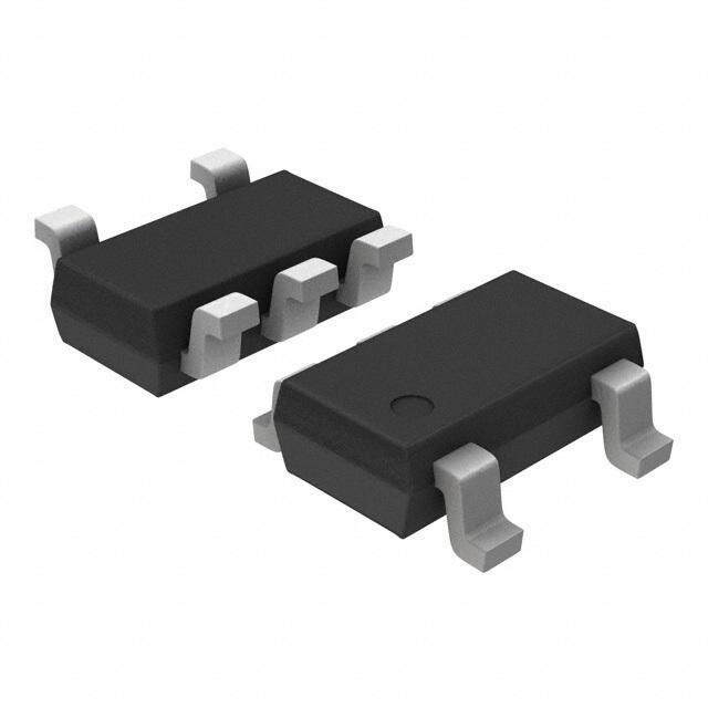
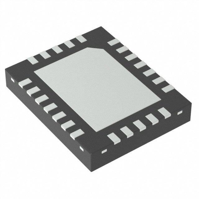
| 产品图片 |
|
| 产品型号 | TPS61180RTER |
| rohs | 无铅 / 符合限制有害物质指令(RoHS)规范要求 |
| 产品系列 | - |
| 产品目录页面 | |
| 供应商器件封装 | 16-WQFN(3x3) |
| 其它名称 | 296-23377-6 |
| 内部驱动器 | 是 |
| 包装 | Digi-Reel® |
| 安装类型 | 表面贴装 |
| 封装/外壳 | 16-WFQFN 裸露焊盘 |
| 工作温度 | -40°C ~ 85°C |
| 恒压 | - |
| 恒流 | - |
| 拓扑 | PWM,升压(升压) |
| 标准包装 | 1 |
| 电压-电源 | 5 V ~ 24 V |
| 电压-输出 | 39V |
| 类型-初级 | 背光 |
| 类型-次级 | 白色 LED |
| 输出数 | 6 |
| 频率 | 900kHz ~ 1.2MHz |


- 商务部:美国ITC正式对集成电路等产品启动337调查
- 曝三星4nm工艺存在良率问题 高通将骁龙8 Gen1或转产台积电
- 太阳诱电将投资9.5亿元在常州建新厂生产MLCC 预计2023年完工
- 英特尔发布欧洲新工厂建设计划 深化IDM 2.0 战略
- 台积电先进制程称霸业界 有大客户加持明年业绩稳了
- 达到5530亿美元!SIA预计今年全球半导体销售额将创下新高
- 英特尔拟将自动驾驶子公司Mobileye上市 估值或超500亿美元
- 三星加码芯片和SET,合并消费电子和移动部门,撤换高东真等 CEO
- 三星电子宣布重大人事变动 还合并消费电子和移动部门
- 海关总署:前11个月进口集成电路产品价值2.52万亿元 增长14.8%


PDF Datasheet 数据手册内容提取
TPS61180/1/2 www.ti.com SLVS801E–DECEMBER2007–REVISEDAPRIL2013 WLED DRIVER FOR NOTEBOOK DISPLAY CheckforSamples:TPS61180/1/2 FEATURES 1 • 5Vto24VInputVoltage • DriverforInput/OutputIsolationPFET • Integrated1.5A40VMOSFET • TrueShutdown • 1.0MHz/1.3MHzSwitchingFrequency • OverVoltageProtection • BoostOutputAuto-AdaptivetoWLEDVoltages • WLEDOpen/ShortProtection • SmallExternalComponents • Built-inSoftStart • IntegratedLoopCompensation • 16L3mm×3mmQFN • SixCurrentSinkof25mA APPLICATIONS • Upto10WLEDinSeries • LessThan3%CurrentMatchingandAccuracy • NotebookLCDDisplayBacklight • Upto1000:1PWMBrightnessDImmingRange • UMPCLCDDisplayBacklight • MinimizedOutputRippleUnderPWMDimming • BacklightforMediaFormFactorLCDdisplay DESCRIPTION The TPS61180/1/2 ICs provide highly integrated solutions for media size LCD backlight. These devices have a built-in high efficiency boost regulator with integrated 1.5A/40V power MOSFET. The six current sink regulators provide high precision current regulation and matching. In total, the device can support up to 60 WLED. In addition,theboostoutputautomaticallyadjustsitsvoltagetotheWLEDforwardvoltagetoimproveefficiency. The devices support pulse width modulation (PWM) brightness dimming. During dimming, the WLED current is turned on/off at the duty cycle and frequency determined by the PWM signal input on the DCRTL pin. One potential issue of PWM dimming is audible noises from the output ceramic capacitors. The TPS61180/1/2 family is designed to minimize this output AC ripple across a wide dimming duty cycle and frequency range; therefore, reducingtheaudiblenoise. The TPS61180/1/2 ICs provide a driver output for an external PFET connected between the input and inductor. During short circuit or over-current conditions, the ICs turn off the external PFET and disconnect the battery from the WLEDs. The PFET is also turned off during IC shutdown (true shutdown) to prevent any leakage current of thebattery.Thedevicealsointegratesover-voltageprotection,soft-startandthermalshutdown. The TPS61180 IC requires external 3.3V IC supply, while TPS61181 and TPS61182 ICs have a built-in linear regulatorfortheICsupply.Allthedevicesareina3×3mmQFNpackage. 1 Pleasebeawarethatanimportantnoticeconcerningavailability,standardwarranty,anduseincriticalapplicationsof TexasInstrumentssemiconductorproductsanddisclaimerstheretoappearsattheendofthisdatasheet. PRODUCTIONDATAinformationiscurrentasofpublicationdate. Copyright©2007–2013,TexasInstrumentsIncorporated Products conform to specifications per the terms of the Texas Instruments standard warranty. Production processing does not necessarilyincludetestingofallparameters.
TPS61180/1/2 SLVS801E–DECEMBER2007–REVISEDAPRIL2013 www.ti.com This integrated circuit can be damaged by ESD. Texas Instruments recommends that all integrated circuits be handled with appropriateprecautions.Failuretoobserveproperhandlingandinstallationprocedurescancausedamage. ESDdamagecanrangefromsubtleperformancedegradationtocompletedevicefailure.Precisionintegratedcircuitsmaybemore susceptibletodamagebecauseverysmallparametricchangescouldcausethedevicenottomeetitspublishedspecifications. Optional L1 10mH D1 C2 5 V to24 V Q1 4.7mF 10WLED in series,120mAtotal R3 R2 D2 C1 100 kW 51Ω 4.7mF Fault SW VBAT VO C3 1mF TPS61181/2 IFB1 IFB2 Cin C4 IFB3 0.1mF IFB4 IFB5 EN EN IFB6 DCTRL PGND PWM Dimming ISET GND R1 62 kW Figure1. TPS61181/2TYPICALAPPLICATION ORDERINGINFORMATION(1) PACKAGE ICSUPPLY SWITCHINGFREQUENCY PACKAGEMARKING (TYP) TPS61180RTE External3.3V 1.0MHz CCG TPS61181RTE Built-inLDO 1.0MHz CCH TPS61182RTE Built-inLDO 1.3MHz CCI (1) Forthemostcurrentpackageandorderinginformation,seethePackageOptionAddendumattheend ofthisdocument,orseetheTIwebsiteatwww.ti.com. 2 SubmitDocumentationFeedback Copyright©2007–2013,TexasInstrumentsIncorporated ProductFolderLinks:TPS61180/1/2
TPS61180/1/2 www.ti.com SLVS801E–DECEMBER2007–REVISEDAPRIL2013 PINOUT QFN PACKAGE 16 Pin 3x3 (TOPVIEW) Fault EN IFB6 IFB5 16 15 14 13 PGND 1 12 IFB4 SW 2 11 DCTRL V 3 10 GND BAT V 4 9 IFB3 O 5 6 7 8 T n 1 2 E Ci B B S F F I I I TERMINALFUNCTIONS TERMINAL I/O DESCRIPTION NO. NAME 1 PGND I PowergroundoftheIC.Internally,itconnectstothesourceofthePWMswitch. 2 SW I ThispinconnectstothedrainoftheinternalPWMswitch,externalSchottkydiodeandinductor. 3 V I Thispinisconnectedtothebatterysupply.Itprovidesthepull-upvoltagefortheFaultpinandbattery BAT voltagesignal.ForTPS61181/2,thisisalsotheinputtotheinternalLDO. 4 V O Thispinmonitorstheoutputoftheboostregulator.ConnectthispintotheanodeoftheWLEDstrings. O 5 ISET I TheresistoronthispinprogramstheWLEDoutputcurrent. 6 Cin I SupplyvoltageoftheIC.ForTPS61181/2,itistheoutputoftheinternalLDO.Connect0.1μFbypass capacitortothispin.ForTPS61180,connectanexternal3.3VsupplytopowertheIC. 7,8,9 IFB1-IFB3 I Currentsinkregulationinputs.TheyareconnectedtothecathodeofWLEDs.ThePWMloopregulates 12,13,14 IFB4-IFB6 thelowestV to400 mV.Eachchannelislimitedto25mAcurrent. IFB 10 GND I SignalgroundoftheIC. 11 DCTRL I Dimmingcontrollogicinput.Thedimmingfrequencyrangeis100Hzto1kHz. 15 EN I TheenablepintotheIC.ForTPS61181/2,alogichighsignalturnsontheinternalLDOandenablesthe IC.Therefore,donotconnecttheENpintotheCinpin. 16 Fault I GatedriveroutputforanexternalPFETusedforfaultprotection.Itcanalsobeusedassignaloutputfor systemfaultreport. Copyright©2007–2013,TexasInstrumentsIncorporated SubmitDocumentationFeedback 3 ProductFolderLinks:TPS61180/1/2
TPS61180/1/2 SLVS801E–DECEMBER2007–REVISEDAPRIL2013 www.ti.com FUNCTIONAL BLOCK DIAGRAM Optional L1 5 V to 24 V 10mH D1 10WLED in series,120mAtotal Q1 R3 C1 R3 100 kW D2 C2 4.7mF 51W 4.7mF Fault SW VO VBAT Fault Current Mode IFB1...IFB6 C3 Protection PWM Control 1mF Cin Internal Regulator C4 (TPS61181/2 only) IFB1 0.1mF GND Dimming IFB2 Control IFB3 IFB4 IFB5 EN EN Current IFB6 DCTRL Regulator PWM Dimming PGND ISET R1 ABSOLUTE MAXIMUM RATINGS overoperatingfree-airtemperaturerange(unlessotherwisenoted) (1) VALUE UNIT VoltagesonpinV andFault(2) –0.3to24 V BAT VoltageonpinCin(2) –0.3to3.6 V VoltageonpinSWandV (2) –0.3to40 V O VoltageonpinIFB1toIFB6(2) –0.3to20 V Voltageonallotherpins (2) –0.3to7 V Continuouspowerdissipation SeeDissipationRatingTable Operatingjunctiontemperaturerange –40to150 °C Storagetemperaturerange –65to150 °C (1) Stressesbeyondthoselistedunderabsolutemaximumratingsmaycausepermanentdamagetothedevice.Thesearestressratings only,andfunctionaloperationofthedeviceattheseoranyotherconditionsbeyondthoseindicatedunderrecommendedoperating conditionsisnotimplied.Exposuretoabsolute-maximum-ratedconditionsforextendedperiodsmayaffectdevicereliability. (2) Allvoltagevaluesarewithrespecttonetworkgroundterminal. DISSIPATION RATINGS PACKAGE R T ≤25°C T =70°C T =85°C θJA A A A POWERRATING POWERRATING POWERRATING TPS61180/1/2RTE(1) 270°C/W 370mW 204mW 148mW TPS61180/1/2RTE(2) 48.7°C/W 2.05W 1.13W 821mW (1) TheJEDEClow-K(1s)boardusedtoderivethisdatawasa3in×3in,two-layerboardwith2-ouncecoppertracesontopoftheboard. (2) TheJEDEChigh-K(2s2p)boardusedtoderivethisdatawasa3in×3in,multilayerboardwith1-ounceinternalpowerandground. 4 SubmitDocumentationFeedback Copyright©2007–2013,TexasInstrumentsIncorporated ProductFolderLinks:TPS61180/1/2
TPS61180/1/2 www.ti.com SLVS801E–DECEMBER2007–REVISEDAPRIL2013 RECOMMENDED OPERATING CONDITIONS MIN TYP MAX UNIT V Batteryinputvoltagerange 5.0 24 V bat C ICsupplyvoltagerange 2.7 3.6 V in V Outputvoltagerange Vin 38 V O L Inductor 4.7 10 μH C Inputcapacitor 1 μF I C Outputcapacitor 2.2 10 μF O F PWMdimmingfrequency 0.1 1 kHz PWM T Operatingambienttemperature –40 85 °C A T Operatingjunctiontemperature –40 125 °C J ELECTRICAL CHARACTERISTICS V =10.8 V,0.1μFatCin,EN=LogicHigh,IFBcurrent=15mA,IFBvoltage=500mV,T =–40°Cto85°C,typical BAT A valuesareatT =25°C(unlessotherwisenoted) A PARAMETER TESTCONDITIONS MIN TYP MAX UNIT SUPPLYCURRENT V Batteryinputvoltagerange 5.0 24 V BAT V ICsupplyvoltagerange TPS61180only 2.7 3.15 3.6 V cc V Cinpinoutputvoltage TPS61181/TPS61182only 2.7 3.15 3.6 V cin Deviceenable,switching TPS61180 1 Iq_bat OperatingquiescentcurrentintoVBAT noload,Vin=24V mA TPS61181/2 3 I OperatingquiescentcurrentintoCinpin TPS61180only 2 mA q_Vcc I OperatingquiescentcurrentintoV V =35V 50 μA Q_sw O O I Shutdowncurrent EN=GND 2 18 μA SD V Cinpinunder-voltagelockoutthreshold TPS61180only 2.2 2.4 V cc_UVLO V V under-voltagelockoutthreshold WhenVinrampdown 4.2 4.5 V bat_UVLO BAT V V under-voltagelockouthysteresis WhenVinrampup 300 mV bat_hys BAT ENANDDCTRL V Logichighvoltage 1.2 V H V Logiclowvoltage 0.4 V L R Pulldownresistoronbothpins 400 800 1600 kΩ PD TPS61180/1 27 37 T ENpulsewidthtoshutdown ENhightolow ms SD TPS61182 21 28 CURRENTREGULATION V ISETpinvoltage 1.204 1.229 1.253 V ISET K CurrentmultipleIout/ISET ISETcurrent=15μAand25μA 970 1000 1030 ISET IFB Currentaccuracy Riset=62K 19.4 20 20.6 mA K (I –I )/I ISETcurrent=15μAand25μA 1 2.5 % m max min AVG I IFBpinleakagecurrent IFBvoltage=20Vonallpins 3 μA leak I Currentsinkmaxoutputcurrent IFB=425mV 25 mA IFB_MAX BOOSTOUTPUTREGULATION V V dialupthreshold MeasuredonV (min) 400 mV IFB_L O IFB V V dialdownthreshold MeasuredonV (min) 700 mV IFB_H O IFB V MinVoutregulationvoltage 16 V reg_L V V steppingvoltage 100 150 mV o_step O POWERSWITCH R PWMFETon-resistance V =3.3VforTPS61180 0.2 0.45 Ω PWM_SW CC R Startupchargingresistance V =0V 100 300 Ω start O Copyright©2007–2013,TexasInstrumentsIncorporated SubmitDocumentationFeedback 5 ProductFolderLinks:TPS61180/1/2
TPS61180/1/2 SLVS801E–DECEMBER2007–REVISEDAPRIL2013 www.ti.com ELECTRICAL CHARACTERISTICS (continued) V =10.8 V,0.1μFatCin,EN=LogicHigh,IFBcurrent=15mA,IFBvoltage=500mV,T =–40°Cto85°C,typical BAT A valuesareatT =25°C(unlessotherwisenoted) A PARAMETER TESTCONDITIONS MIN TYP MAX UNIT V IsolationFETstartupthreshold V –V ,V rampup 1.2 2 V start_r IN O O I PWMFETleakagecurrent V =35V,T =25°C 1 μA LN_NFET SW A OSCILLATOR TPS61182 1.2 1.3 1.5 f Oscillatorfrequency MHz S TPS61180/1 0.9 1.0 1.2 D Maximumdutycycle IFB=0V 85 94 % max TPS61182 8 D Minimumdutycycle % min TPS61180/1 7 OS,SC,OVPANDSS I N-ChannelMOSFETcurrentlimit D=D 1.5 3 A LIM max V V overvoltagethreshold MeasuredontheV pin 38 39 40 V ovp O O V IFBovervoltagethreshold MeasuredontheIFBxpin 15 17 20 V ovp_IFB V Shortcircuitdetectionthreshold V -V ,V rampdown 1.7 2.5 V sc IN O O V Shortcircuitdetectiondelayduringstartup 32 ms sc_dly V IFBnousedetectionthreshold TPS61180Only 0.6 V IFB_nouse FaultOUTPUT V Faulthighvoltage MeasuredasV –V 0.1 V fault_high bat Fault V Faultlowvoltage MeasuredasV –V ,sink0.1mA,Vin 6 8 10 V fault_low bat Fault =15V THERMALSHUTDOWN T Thermalshutdownthreshold 160 °C shutdown T Thermalshutdownthresholdhysteresis 15 °C hysteresis 6 SubmitDocumentationFeedback Copyright©2007–2013,TexasInstrumentsIncorporated ProductFolderLinks:TPS61180/1/2
TPS61180/1/2 www.ti.com SLVS801E–DECEMBER2007–REVISEDAPRIL2013 TYPICAL CHARACTERISTICS TableofGraphs Figure LoadEfficiencyTPS61181 V =11V;V =28.8V,23.2Vand17.6V;L=4.7uH Figure2 bat O LoadEfficiencyTPS61181 V =11V;V =36.2Vand31.6V;L=4.7uH Figure3 bat O LoadEfficiencyTPS61181 V =11V;V =28.8V;L=4.7uH,L=10uH Figure4 bat O LoadEfficiencyTPS61181 V =7V,11Vand19V;V =28.8V;L=4.7uH Figure5 bat O PWMDimmingEfficiency V =7V,11Vand19V;V =28.8V;I =20μA;PWMFreq=200Hz Figure6 bat O set PWMDimmingEfficiency V =7V,11Vand19V;V =36.2V;I =20μA;PWMFreq=200Hz Figure7 bat O set DimmingLinearity V =11V;V =28.8V;I =20μA;PWMFreq=1kHz Figure8 bat O set DimmingLinearity V =11V;V =28.8V;I =20μA;PWMFreq=200Hz Figure9 bat O set OutputRipple V =28.8V;I =20μA;PWMFreq=200Hz;Duty=50% Figure10 O set SwitchingWaveform V =11V;I =20μA Figure11 bat set OutputRippleatPWMDimming V =11V;I =20μA;PWMFreq=200Hz;Duty=50%;C =4.7μF Figure12 bat set O ShortCircuitProtection V =11V;I =20μA Figure13 bat set OpenWLEDProtection V =11V;I =20μA Figure14 bat set StartupWaveform V =11V;I =20μA Figure15 bat set EFFICIENCY EFFICIENCY vs vs OUTPUTCURRENT OUTPUTCURRENT 100 100 Vbat= 11 V Vbat= 11 V 98 98 96 V = 23.2 V 96 O V = 17.6 V O 94 94 VO= 31.6 V % % y - 92 y - 92 c c n 90 V = 28.8 V n 90 e O e Effici 88 Effici 88 VO= 36.2 V 86 86 84 84 82 82 80 80 0 25 50 75 100 125 150 0 25 50 75 100 125 150 IO- Output Current - mA IO- Output Current - mA Figure2. Figure3. Copyright©2007–2013,TexasInstrumentsIncorporated SubmitDocumentationFeedback 7 ProductFolderLinks:TPS61180/1/2
TPS61180/1/2 SLVS801E–DECEMBER2007–REVISEDAPRIL2013 www.ti.com EFFICIENCY EFFICIENCY vs vs OUTPUTCURRENT OUTPUTCURRENT 100 100 V = 11 V bat 98 98 96 96 Vbat= 19 V Vbat= 11 V 10mH 94 94 % % y - 92 y - 92 nc 90 4.7mH nc 90 e e ci ci Effi 88 Effi 88 Vbat= 7 V 86 86 84 84 V = 28.8 V, O V = 28.8 V, O TPS61181 82 82 TPS61181 80 80 0 25 50 75 100 125 150 0 25 50 75 100 125 150 I - Output Current - mA I - Output Current - mA O O Figure4. Figure5. EFFICIENCY EFFICIENCY vs vs DIMMINGDUTYCYCLE DIMMINGDUTYCYCLE 100 100 Vbat= 19 V Vbat= 19 V 90 90 V = 11 V y - % 80 Vbat= 7 V bat y - % 80 Vbat= 11 V c c n n V = 7 V e e bat ci ci Effi 70 Effi 70 60 VO= 28.8 V, TPS61181 60 VO= 36.2 V - TPS61181 ISET = 20mA, ISET = 20mA Dimming Frequency = 200 Hz Dimming Frequency = 200 Hz 50 50 0 10 20 30 40 50 60 70 80 90 100 0 10 20 30 40 50 60 70 80 90 100 PWM Dimming Duty Cycle - % PWM Dimming Duty Cycle - % Figure6. Figure7. 8 SubmitDocumentationFeedback Copyright©2007–2013,TexasInstrumentsIncorporated ProductFolderLinks:TPS61180/1/2
TPS61180/1/2 www.ti.com SLVS801E–DECEMBER2007–REVISEDAPRIL2013 PWMDIMMINGlinearity1kHz PWMDIMMINGLINEARITY200Hz 140 140 120 120 A A 100 m 100 m nt - ent - e 80 r 80 rr ur u C ut C 60 put 60 utp Out - OO 40 I- O 40 I TPS61181 TPS61181 20 ISET = 20mA, 20 ISET = 20mA, Dimming Frequency = 1 kHz Dimming Frequency = 200 Hz 0 0 0 10 20 30 40 50 60 70 80 90 100 0 10 20 30 40 50 60 70 80 90 100 PWM Dimming Duty Cycle - % PWM Dimming Duty Cycle - % Figure8. Figure9. PWMDIMMINGOUTPUTRIPPLEC =4.7μF O vs INPUTVOLTAGE 350 300 mV L= 4.7mH k - 250 a e P o ak t 200 e P e pl L= 10mH p 150 Ri ut utp VO= 28.8 V, TPS61181 O 100 ISET = 20mA, Dimming Frequency = 200 Hz 50 5 7.5 10 12.5 15 17.5 20.0 V - V bat Figure10. Copyright©2007–2013,TexasInstrumentsIncorporated SubmitDocumentationFeedback 9 ProductFolderLinks:TPS61180/1/2
TPS61180/1/2 SLVS801E–DECEMBER2007–REVISEDAPRIL2013 www.ti.com SWITCHINGWAVEFORM OUTPUTRIPPLEATPWMDIMMINGC =4.7μF O V bat 100 mV/div,AC DCTRL 5 V/div, DC SW 20 V/div, DC V O 100 mV/div,AC V O 100 mV/div,AC Inductor Inductor Current Current 1A/div, DC 1A/div, DC t - Time - 1ms/div t - Time - 2ms/div Figure11. Figure12. OUTPUTSHORTPROTECTION OPENWLEDPROTECTION Fault Fault 5 V/div, DC 5 V/div, DC V V O O 20 V/div, DC 20 V/div, DC Inductor Inductor Current Current 5A/div, DC 1A/div, DC t - Time - 100ms/div t - Time - 1 s/div Figure13. Figure14. STARTUPWAVEFORM EN 5 V/div, DC V O 10 V/div, DC Inductor Current 1A/div, DC WLED Current 20 mA/div, DC t - Time - 10ms/div Figure15. 10 SubmitDocumentationFeedback Copyright©2007–2013,TexasInstrumentsIncorporated ProductFolderLinks:TPS61180/1/2
TPS61180/1/2 www.ti.com SLVS801E–DECEMBER2007–REVISEDAPRIL2013 DETAILED DESCRIPTION Recently, WLEDs have gained popularity as an alternative to CCFL for backlighting media size LCD displays. The advantages of WLEDs are power efficiency and low profile design. Due to the large number of WLEDs, they are often arranged in series and parallel, and powered by a boost regulator with multiple current sink regulators. Having more WLEDs in series reduces the number of parallel strings and therefore improves overall current matching. However, the efficiency of the boost regulator declines due to the need for high output voltage. Also, there have to be enough WLEDs in series to ensure the output voltage stays above the input voltage range. Otherwise, a buck-boost (for example, SEPIC) power converter has to be adopted which could be more expensiveandcomplicated. The TPS61180/1/2 family of ICs have integrated all the key function blocks to power and control up to 60 WLEDs. The devices include a 40V/1.5A boost regulator, six 25mA current sink regulators and protection circuit for over-current, over-voltage and short circuit failures. The key advantages of the devices are small solution size, low output AC ripple during PWM dimming control, and the capability to isolate the input and output during faultconditions. SUPPLY VOLTAGE The TPS61181/2 ICs have built-in LDO linear regulator to supply the IC analog and logic circuit. The LDO is powered up when the EN pin is high. The output of the LDO is connected to the Cin pin. A 0.1μF bypass capacitor is required for LDO’s stable operation. Do not connect the Cin pin to the EN pin because this prevents the IC from starting up. In addition, avoid connecting the Cin pin to any other circuit as this could introduce noise intotheICsupplyvoltage. The TPS61180 has no built-in LDO linear regulator, and therefore requires an external supply voltage in the range of 2.7V to 3.6V connected to the Cin pin. The benefit of using external supply is to reduce the power losses incurred by the LDO as it provides the IC supply current. This loss could become a significant percentage of total output power under light load condition. The Cin pin has 2.2V (typical) under-voltage lock out which turns offtheICwhentheCinpinvoltageisbelowthisthreshold. The voltage on the V pin is the reference for the pull-up circuit of the Fault pin. In addition, it also serves as BAT the input signal to the short circuit protection. For TPS61181/2 ICs, the V connects to the input of the internal BAT LDO, and powers the IC. There is an under-voltage lockout on the V pin which disables the IC when its BAT voltagereducesto4.2V(Typical).TheICrestartswhentheV pinvoltagerecoversby300mV. BAT BOOST REGULATOR The boost regulator is controlled by current mode PWM, and loop compensation is integrated inside the IC. The internal compensation ensures stable output over the full input and output voltage range. The TPS61180/1 switches at 1.0MHz, and the TPS61182 switches at 1.3MHz. The switching frequencies of the two devices, including their tolerance, due not over-lap. Therefore, in the unlikely event that one device creates electromagnetic inference to the system; the other device, switching at a different frequency, can provide an alternativesolution. The output voltage of the boost regulator is automatically set by the IC to minimize the voltage drop across the IFB pins. The IC automatically regulates the lowest IFB pin to 400mV, and consistently adjusts the boost output voltagetoaccountforanychangesoftheLEDforwardvoltages. When the output voltage is too close to the input, the boost regulator may not be able to regulate the output due to the limitation of minimum duty cycle. In this case, increase the number of WLED in series or include series ballastresistorsinordertoprovideenoughheadroomfortheboostoperation. TheTPS61180/1/2boostregulatorscannotregulatetheiroutputstovoltagesbelow15V. Copyright©2007–2013,TexasInstrumentsIncorporated SubmitDocumentationFeedback 11 ProductFolderLinks:TPS61180/1/2
TPS61180/1/2 SLVS801E–DECEMBER2007–REVISEDAPRIL2013 www.ti.com CURRENT PROGRAM AND PWM DIMMING The six current sink regulators can each provide maximum 25mA. The IFB current must be programmed to highestWLEDcurrentexpectedusingtheISETpinresistorandthefollowingEquation1. V I (cid:1)K ISET FB ISETR ISET (1) Where K =Currentmultiple(1000typical) ISET V =ISETpinvoltage(1.229Vtypical) ISET R =ISETpinresistor ISET The TPS61180/1/2 ICs have built-in precise current sink regulator. The current matching among 6 current sinks is below 2.5%. This means the differential value between the maximum and minimum current of the six current sinksdividedbytheaveragecurrentofthesixislessthan2.5%. The WLED brightness is controlled by the PWM signal on the DCTRL pin. The frequency and duty cycle of the DCTRL signal is replicated on the IFB pin current. Keep the dimming frequency in the range of 100Hz to 1kHz to avoid screen flickering and maintain dimming linearity. Screen flickering may occur if the dimming frequency is below the range. The minimum achievable duty cycle increases with the dimming frequency. For example, while a0.1%dimmingdutycycle,givinga1000:1dimmingrange,isachievableat100Hzdimmingfrequency,only1% duty cycle, giving a 100:1 dimming range, is achievable with a 1 KHz dimming frequency, and 5% dimming duty cycleisachievablewith5KHzdimmingfrequency.Thedevicecouldworkathighdimmingfrequencylike20KHz, but only 15% duty cycle could be achievable. The TPS61180/1/2 ICs are designed to minimize the AC ripple on the output capacitor during PWM dimming. Careful passive component selection is also critical to minimize AC rippleontheoutputcapacitor.SeeAPPLICATIONINFORMATIONformoreinformation. ENABLE AND START UP A logic high signal on the EN pin turns on the IC. For the TPS61181/2 ICs, taking EN high turns on the internal LDOlinearregulatorwhichprovidessupplyICcurrent.Foralldevices,aninternalresistorR (startupcharging start resistor) is connected between the V pin and V pin to charge the output capacitor toward Vin. The Fault pin BAT O outputs high during this time, and thus the external isolation PFET is turned off. Once the V pin voltage is within O 2 V (isolation FET start up threshold) of the V pin voltage, R is open, and the Fault pin pulls down the gate BAT start of the PFET and connects the V voltage to the boost regulator. This operation is to prevent the in-rush current BAT duetochargingtheoutputcapacitor. Once the isolation FET is turned on, the IC starts the PWM switching to raise the output voltage above V . BAT Soft-start is implemented by gradually ramping up the reference voltage of the error amplifier to prevent voltage over-shootandin-rushcurrent.Seethestart-upwaveformofatypicalexample,Figure15. Pulling the EN pin low for 32ms (typical) shuts down the IC, resulting in the IC consuming less than 50μA in the shutdownmode. OVER-CURRENT, OVER-VOLTAGE AND SHORT-CIRCUIT PROTECTION TheTPS61180/1/2familyhaspulsebypulseover-currentlimitof1.5A(min).ThePWMswitchturnsoffwhenthe inductor current reaches this current threshold. The PWM switch remains off until the beginning of the next switching cycle. This protects the IC and external component under over-load conditions. When there is sustained over-current condition for more than 16ms ( under 100% dimming duty cycle), the IC turns off and requiresPERortheENpintogglingtorestart. Undersevereover-loadand/orshortcircuitconditions,theV pincanbepulledbelowtheinput(V pin).Under O BAT this condition, the current can follow directly from input to output through the inductor and Schottky diode. Turning off the PWM switch alone does not limit current anymore. In this case, the TPS61180/1/2 ICs detect the output voltage is 1V (short circuit detection threshold) below the input voltage, turns off the isolation FET, and shutsdowntheIC.TheICrestartsafterinputpower-onreset(V POR)orENpinlogictoggling. BAT During the IC start up, if there is short circuit condition on the boost converter output, the output capacitor will not be charged to within 2V of V through R . After 32ms (short circuit detection delay during start up), the IC BAT start shuts down and does not restart until there is V POR or EN pin toggling. The isolation FET is never turned on BAT underthecondition. 12 SubmitDocumentationFeedback Copyright©2007–2013,TexasInstrumentsIncorporated ProductFolderLinks:TPS61180/1/2
TPS61180/1/2 www.ti.com SLVS801E–DECEMBER2007–REVISEDAPRIL2013 For the TPS61181/2 ICs, if one of the WLED strings is open, the boost output rises to over-voltage threshold (39V typical). The IC detects the open WLED string by sensing no current in the corresponding IFB pin. As a result, the IC removes the open IFB pin from the voltage feedback loop. Subsequently, the output voltage drops down and is regulated to a voltage for the connected WLED strings. The IFB current of the connected WLED string keeps in regulation during the whole transition. The IC only shuts down if it detects that all of the WLED stringsareopen. For the TPS61180, if the IC detects any open WLED string, the IC shuts down and remains off until there is V BAT PORorENpintoggling. For all the devices, if the over-voltage threshold is reached, but the current sensed on the IFB pin is below the regulation target, the IC regulates the boost output at the over-voltage threshold. This operation could occur when the WLED is turned on under cold temperature, and the forward voltages of the WLEDs exceed the over- voltage threshold. Maintaining the WLED current allows the WLED to warm up and their forward voltages to drop belowtheover-voltagethreshold. For the TPS61181/2 ICs, if any IFB pin voltage exceeds IFB over-voltage threshold (17V typical), the IC turns off thecorrespondingcurrentsinkandremovesthisIFBpinfromV regulationloop.TheremainingIFBpins’current O regulation is not affected. This condition often occurs when there are several shorted WLEDs in one string. WLEDmismatchtypicallydoesnotcreatesuchlargevoltagedifferenceamongWLEDstrings. For the TPS61180 IC, if any IFB pin voltage exceeds IFB over-voltage threshold, the IC shuts down and remains offuntilthereisV PORorENpintoggling. BAT IFB PIN UNUSED If the application requires less than 6 WLED strings, one can easily disable unused IFB pins. The TPS61181/2 ICs simply require leaving the unused IFB pin open or shorting it to ground. If the IFB pin is open, the boost output voltage ramps up to V over-voltage threshold during start up. The IC then detects the zero current string, O and removes it from the feedback loop. If the IFB pin is shorted to ground, the IC detects the short immediately after IC enable, and the boost output voltage does not go up to V over-voltage threshold. Instead, it ramps to O theregulationvoltageaftersoftstart. For the TPS61180, connect a 10 kΩ resistor from the unused IFB pin to ground. After the device is enabled, the ICdetectstheresistoranddisablestheIFBpinfromthefeedbackloop. Copyright©2007–2013,TexasInstrumentsIncorporated SubmitDocumentationFeedback 13 ProductFolderLinks:TPS61180/1/2
TPS61180/1/2 SLVS801E–DECEMBER2007–REVISEDAPRIL2013 www.ti.com APPLICATION INFORMATION INDUCTOR SELECTION Because the selection of the inductor affects power supply’s steady state operation, transient behavior and loop stability, the inductor is the most important component in switching power regulator design. There are three specifications most important to the performance of the inductor, inductor value, DC resistance and saturation current. The TPS61180/1/2 ICs are designed to work with inductor values between 4.7μH and 10μH. A 4.7μH inductor could be available in a smaller or lower profile package, while 10μH may produce higher efficiency due to lower inductor ripple. If the boost output current is limited by the over-current protection of the IC, using a 10μHinductorcanofferhigheroutputcurrent. The internal loop compensation for the PWM control is optimized for the recommended component values, including typical tolerances. Inductor values can have ±20% tolerance with no current bias. When the inductor currentapproachessaturationlevel,itsinductancecandecrease20to35%fromthe0Avaluedependingonhow theinductorvendordefinessaturation Inaboostregulator,theinductorDCcurrentcanbecalculatedas V (cid:1)I I (cid:2) O O dc V (cid:1)(cid:1) in (2) Where V =boostoutputvoltage O Io=boostoutputcurrent V =boostinputvoltage in η=powerconversionefficiency,use90%forTPS61180/1/2applications Theinductorcurrentpeaktopeakripplecanbecalculatedas 1 Ipp(cid:4) (cid:5) (cid:6) 1 1 L(cid:1) V V (cid:2)V (cid:1)FS O(cid:3) bat bat (3) Where I =inductorpeaktopeakripple pp L=inductorvalue F =Switchingfrequency s V =boostinputvoltage bat Therefore,thepeakcurrentseenbytheinductoris I pp I (cid:2)I (cid:1) p dc 2 (4) Select the inductor with saturation current over the calculated peak current. To calculate the worse case inductor peakcurrent,useminimuminputvoltage,maximumoutputvoltageandmaximumloadcurrent. Regulator efficiency is dependent on the resistance of its high current path, switching losses associated with the PWM switch and power diode. Although the TPS61180/1/2 ICs have optimized the internal switch resistance, the overall efficiency still relies on the DC resistance (DCR) of the inductor; lower DCR improves efficiency. However, there is a trade off between DCR and inductor footprint. Furthermore, shielded inductors typically have ahigherDCRthanunshieldedones.Table1listsrecommendedinductormodels. 14 SubmitDocumentationFeedback Copyright©2007–2013,TexasInstrumentsIncorporated ProductFolderLinks:TPS61180/1/2
TPS61180/1/2 www.ti.com SLVS801E–DECEMBER2007–REVISEDAPRIL2013 Table1.RecommendedInductorforTPS61180/1/2 L DCRTyp I Size sat (μH) (mΩ) (A) (LXWXHmm) TOKO A915AY-4R7M 4.7 38 1.87 5.2x5.2x3.0 A915AY-100M 10 75 1.24 5.2x5.2x3.0 TDK SLF6028T-4R7M1R6 4.7 28.4 1.6 6.0x6.0x2.8 SLF6028T-100M1R3 10 53.2 1.3 6.0x6.0x2.8 OUTPUT CAPACITOR SELECTION During PWM brightness dimming, the load transient causes voltage ripple on the output capacitor. Since the PWM dimming frequency is in the audible frequency range, the ripple can produce audible noises on the output ceramiccapacitor.Therearetwowaystoreduceoreliminatethisaudiblenoise.ThefirstoptionistoselectPWM dimming frequency outside the audible range. This means the dimming frequency needs be to lower than 200Hz or higher than 30KHz. The potential issue with low dimming frequency is that WLED on/off can become visible and thus cause a flickering effect on the display. On the other hand, high dimming frequency can compromise the dimming range since the LED current accuracy and current match are difficult to maintain at low dimming duty cycle. The TPS61180/1/2 ICs can support minimum 1% dimming duty cycle up to 1KHz dimming frequency. Thesecondoptionistoreducetheamountoftheoutputripple,andthereforeminimizetheaudiblenoise. The TPS61180/1/2 ICs adopt a patented technology to limit output ripple even with small output capacitance. In a typical application, the output ripple is less than 200mV during PWM dimming with 4.7μF output capacitor, and the audible noise is not noticeable. The devices are designed to be stable with output capacitor down to 1.0μF. However,theoutputripplecanincreasewithloweroutputcapacitor. Care must be taken when evaluating a ceramic capacitor’s derating due to applied dc voltage, aging and over frequency. For example, larger form factor capacitors (in 1206 size) have their self resonant frequencies in the switching frequency range of the TPS61180/1/2. So the effective capacitance is significantly lower. Therefore, it maybenecessarytousesmallcapacitorsinparallelinsteadofonelargecapacitor. ISOLATION MOSFET SELECTION The TPS61180/1/2 ICs provide a gate driver to an external P channel MOSFET which can be turned off during device shutdown or fault condition. This MOSFET can provide a true shutdown function, and also protect the battery from output short circuit conditions. The source of the PMOS should be connected to the input, and a pull up resistor is required between the source and gate of the FET to keep the FET off during IC shutdown. To turn ontheisolationFET,theFaultpinispulledlow,andclampedat8VbelowtheV pinvoltage. BAT During device shutdown or fault condition, the isolation FET is turned off, and the input voltage is applied on the isolation MOSFET. During short circuit condition, the catch diode (D2 in typical application circuit) is forward biased when the isolation FET is turned off. The drain of the isolation FET swings below ground. The voltage cross the isolation FET can be momentarily greater than the input voltage. Therefore, select 30V PMOS for 24V maximum input. The on resistor of the FET has large impact on power conversion efficiency since the FET carriestheinputvoltage.SelectaMOSFETwithR lessthan100mΩ tolimitthepowerlosses. ds(on) AUDIBLE NOISE REDUCTION Ceramic capacitors can produce audible noise if the frequency of its AC voltage ripple is in the audible frequency range. In TPS61180/1/2 applications, both input and output capacitors are subject to AC voltage ripple during PWM brightness dimming. The ICs integrate a patented technology to minimize the ripple voltage, and thus audiblenoises. To further reduce the audible noise, one effective way is to use two or three small size capacitors in parallel instead of one large capacitor. The application circuit in Figure 16uses two 2.2-μF/25V ceramic capacitors at the input and two 1-μF/50V ceramic capacitors at the output. All of the capacitors are in 0805 package. Although the output ripple during PWM dimming is higher than one 4.7μF in a 1206 package, the overall audible noise is lower. Copyright©2007–2013,TexasInstrumentsIncorporated SubmitDocumentationFeedback 15 ProductFolderLinks:TPS61180/1/2
TPS61180/1/2 SLVS801E–DECEMBER2007–REVISEDAPRIL2013 www.ti.com In addition, connecting a 10-nF/50V ceramic capacitor between the V pin and IFB1 pin can further reduce the O output AC ripple during the PWM dimming. Since this capacitor is subject to large AC ripple, choose a small packagesuchas0402topreventitfromproducingnoise. LAYOUT CONSIDERATION As for all switching power supplies, especially those providing high current and using high switching frequencies, layout is an important design step. If layout is not carefully done, the regulator could show instability as well as EMI problems. Therefore, use wide and short traces for high current paths. The input capacitor, C3 in the typical applicationcircuit,needsnotonlytobeclosetotheV pin,butalsototheGNDpininordertoreducetheinput BAT ripple seen by the IC. The input capacitor, C1 in the typical application circuit, should be placed close to the inductor. The SW pin carries high current with fast rising and falling edges. Therefore, the connection between thepintotheinductorandSchottkyshouldbekeptasshortandwideaspossible.Itisalsobeneficialtohavethe ground of the output capacitor C2 close to the PGND pin since there is large ground return current flowing between them. When laying out signal ground, it is recommended to use short traces separated from power groundtraces,andconnectthemtogetheratasinglepoint,forexampleonthethermalpad. Thermal pad needs to be soldered on to the PCB and connected to the GND pin of the IC. Additional thermal via cansignificantlyimprovepowerdissipationoftheIC. ADDITIONAL APPLICATION CIRCUITS Optional L1 C2 C2a 10mH D1 5 V to 24 V Q1 1mF 1mF 10WLED in series,120 mAtotal R2 R3 C1 C1a 51Ω 100 kW D2 2.2mF 2.2mF Fault SW C5 10nF VBAT V O C3 1mF TPS61181/2 IFB1 IFB2 Cin C4 IFB3 0.1mF IFB4 IFB5 EN EN IFB6 PWM Dimming DCTRL PGND ISET GND R1 C1,C1a:Murata GRM219R61E225K L1:TOKOA915AY-100M C2,C2a:Murata GRM21BR71H105K D1:VISHAYSS2P5-E3/84A C3:Murata GRM21BR71H105K C4:Murata GRM185R61A105K C5:Murata GRM155R71H103K Figure16. AudibleNoiseReductionCircuit 16 SubmitDocumentationFeedback Copyright©2007–2013,TexasInstrumentsIncorporated ProductFolderLinks:TPS61180/1/2
TPS61180/1/2 www.ti.com SLVS801E–DECEMBER2007–REVISEDAPRIL2013 L1 Optional 10mH D1 C2 5V to 24V Q1 4.7mF 10WLED in series,120mAtotal R3 R2 D2 C1 100 kW 51Ω 4.7mF Fault SW VBAT V O C3 1mF TPS61181/2 IFB1 IFB2 Cin C4 IFB3 0.1mF IFB4 IFB5 EN/PWM EN IFB6 DCTRL PGND ISET GND R1 62 kW Figure17. SingleInputControlCircuit Optional L1 C2 5V to24V Q1 10mH D1 4.7mF 10WLED in series,120 mAtotal R3 C1 R2 100 kW D2 4.7mF 51Ω Fault SW VBAT V O C3 1mF TPS61180 IFB1 IFB2 3.3 V Cin C4 IFB3 0.1uF IFB4 IFB5 EN EN IFB6 PWM Dimming DCTRL PGND ISET GND R1 62 kW Figure18. TPS61180TypicalApplication Copyright©2007–2013,TexasInstrumentsIncorporated SubmitDocumentationFeedback 17 ProductFolderLinks:TPS61180/1/2
TPS61180/1/2 SLVS801E–DECEMBER2007–REVISEDAPRIL2013 www.ti.com Optional L1 10 WLEDs in Series 10mH 5V to24 V D1 20 mAEach String Q1 C1 R2 R3 D2 C2 4.7mF 4.7mF 51W 100 kW Fault SW C3 VBAT VO 1mF TPS61181/2 IFB1 IFB2 Cin C4 IFB3 0.1mF IFB4 IFB5 EN EN IFB6 PWM DCTRL PGND ISET GND R1 62 kW S0333-01 Figure19. TSP61181/2forThreeStringsofLEDs Optional L1 10 WLEDs in Series 10mH 5V to24 V D1 40 mAEach String Q1 C1 R2 R3 D2 C2 4.7mF 4.7mF 51W 100 kW Fault SW C3 VBAT VO 1mF TPS61181/2 IFB1 IFB2 Cin C4 IFB3 0.1mF IFB4 IFB5 EN EN IFB6 PWM DCTRL PGND ISET GND R1 62 kW S0334-01 Figure20. TSP61181/2forThreeStringsofLEDswithDoubleCurrent 18 SubmitDocumentationFeedback Copyright©2007–2013,TexasInstrumentsIncorporated ProductFolderLinks:TPS61180/1/2
TPS61180/1/2 www.ti.com SLVS801E–DECEMBER2007–REVISEDAPRIL2013 Optional L1 10 WLEDs in Series 10mH 5V to24 V D1 72 mAEach String Q1 C1 R2 R3 D2 C2 4.7mF 4.7mF 51W 100 kW D E L s s Fault SW ne ht C3 VBAT VO Brig 1mF TPS61181/2 IFB1 High- IFB2 Cin C4 IFB3 0.1mF IFB4 IFB5 EN EN IFB6 PWM DCTRL PGND ISET GND R1 51 kW S0335-01 Figure21. TSP61181/2forTwoStringsHighBrightnessLEDsApplication Optional L1 10mH 5V to24 V D1 10 WLEDs 120 mA Q1 C1 R2 R3 D2 C2 4.7mF 4.7mF 51W 100 kW D E L s s Fault SW ne ht C3 VBAT VO Brig 1mF TPS61181/2 IFB1 High- IFB2 Cin C4 IFB3 0.1mF IFB4 IFB5 EN EN IFB6 PWM DCTRL PGND ISET GND R1 62 kW S0336-01 Figure22. TSP61181/2forOneStringHighBrightnessLEDsApplication Copyright©2007–2013,TexasInstrumentsIncorporated SubmitDocumentationFeedback 19 ProductFolderLinks:TPS61180/1/2
TPS61180/1/2 SLVS801E–DECEMBER2007–REVISEDAPRIL2013 www.ti.com REVISION HISTORY ChangesfromRevisionC(April2009)toRevisionD Page • AddedtoELECCHARAtable,subsectionPOWERSWITCH:firstrow,TESTCONDITIONSCol:V =3.3Vfor CC TPS61180 ............................................................................................................................................................................. 5 ChangesfromRevisionD(February2012)toRevisionE Page • ChangedD specfrom7%MAXto8%forTPS61182inElecChartable. ....................................................................... 6 min 20 SubmitDocumentationFeedback Copyright©2007–2013,TexasInstrumentsIncorporated ProductFolderLinks:TPS61180/1/2
PACKAGE OPTION ADDENDUM www.ti.com 6-Feb-2020 PACKAGING INFORMATION Orderable Device Status Package Type Package Pins Package Eco Plan Lead/Ball Finish MSL Peak Temp Op Temp (°C) Device Marking Samples (1) Drawing Qty (2) (6) (3) (4/5) HPA00388RTER ACTIVE WQFN RTE 16 3000 Green (RoHS NIPDAU Level-2-260C-1 YEAR -40 to 85 CCH & no Sb/Br) TPS61180RTER ACTIVE WQFN RTE 16 3000 Green (RoHS NIPDAU Level-2-260C-1 YEAR -40 to 85 CCG & no Sb/Br) TPS61180RTERG4 ACTIVE WQFN RTE 16 3000 Green (RoHS NIPDAU Level-2-260C-1 YEAR -40 to 85 CCG & no Sb/Br) TPS61180RTET ACTIVE WQFN RTE 16 250 Green (RoHS NIPDAU Level-2-260C-1 YEAR -40 to 85 CCG & no Sb/Br) TPS61180RTETG4 ACTIVE WQFN RTE 16 250 Green (RoHS NIPDAU Level-2-260C-1 YEAR -40 to 85 CCG & no Sb/Br) TPS61181RTER ACTIVE WQFN RTE 16 3000 Green (RoHS NIPDAU Level-2-260C-1 YEAR -40 to 85 CCH & no Sb/Br) TPS61181RTERG4 ACTIVE WQFN RTE 16 3000 Green (RoHS NIPDAU Level-2-260C-1 YEAR -40 to 85 CCH & no Sb/Br) TPS61181RTET ACTIVE WQFN RTE 16 250 Green (RoHS NIPDAU Level-2-260C-1 YEAR -40 to 85 CCH & no Sb/Br) TPS61182RTER ACTIVE WQFN RTE 16 3000 Green (RoHS NIPDAU Level-2-260C-1 YEAR -40 to 85 CCI & no Sb/Br) TPS61182RTERG4 ACTIVE WQFN RTE 16 3000 Green (RoHS NIPDAU Level-2-260C-1 YEAR -40 to 85 CCI & no Sb/Br) TPS61182RTET ACTIVE WQFN RTE 16 250 Green (RoHS NIPDAU Level-2-260C-1 YEAR -40 to 85 CCI & no Sb/Br) (1) The marketing status values are defined as follows: ACTIVE: Product device recommended for new designs. LIFEBUY: TI has announced that the device will be discontinued, and a lifetime-buy period is in effect. NRND: Not recommended for new designs. Device is in production to support existing customers, but TI does not recommend using this part in a new design. PREVIEW: Device has been announced but is not in production. Samples may or may not be available. OBSOLETE: TI has discontinued the production of the device. (2) RoHS: TI defines "RoHS" to mean semiconductor products that are compliant with the current EU RoHS requirements for all 10 RoHS substances, including the requirement that RoHS substance do not exceed 0.1% by weight in homogeneous materials. Where designed to be soldered at high temperatures, "RoHS" products are suitable for use in specified lead-free processes. TI may reference these types of products as "Pb-Free". RoHS Exempt: TI defines "RoHS Exempt" to mean products that contain lead but are compliant with EU RoHS pursuant to a specific EU RoHS exemption. Green: TI defines "Green" to mean the content of Chlorine (Cl) and Bromine (Br) based flame retardants meet JS709B low halogen requirements of <=1000ppm threshold. Antimony trioxide based flame retardants must also meet the <=1000ppm threshold requirement. Addendum-Page 1
PACKAGE OPTION ADDENDUM www.ti.com 6-Feb-2020 (3) MSL, Peak Temp. - The Moisture Sensitivity Level rating according to the JEDEC industry standard classifications, and peak solder temperature. (4) There may be additional marking, which relates to the logo, the lot trace code information, or the environmental category on the device. (5) Multiple Device Markings will be inside parentheses. Only one Device Marking contained in parentheses and separated by a "~" will appear on a device. If a line is indented then it is a continuation of the previous line and the two combined represent the entire Device Marking for that device. (6) Lead/Ball Finish - Orderable Devices may have multiple material finish options. Finish options are separated by a vertical ruled line. Lead/Ball Finish values may wrap to two lines if the finish value exceeds the maximum column width. Important Information and Disclaimer:The information provided on this page represents TI's knowledge and belief as of the date that it is provided. TI bases its knowledge and belief on information provided by third parties, and makes no representation or warranty as to the accuracy of such information. Efforts are underway to better integrate information from third parties. TI has taken and continues to take reasonable steps to provide representative and accurate information but may not have conducted destructive testing or chemical analysis on incoming materials and chemicals. TI and TI suppliers consider certain information to be proprietary, and thus CAS numbers and other limited information may not be available for release. In no event shall TI's liability arising out of such information exceed the total purchase price of the TI part(s) at issue in this document sold by TI to Customer on an annual basis. Addendum-Page 2
PACKAGE MATERIALS INFORMATION www.ti.com 7-Jan-2015 TAPE AND REEL INFORMATION *Alldimensionsarenominal Device Package Package Pins SPQ Reel Reel A0 B0 K0 P1 W Pin1 Type Drawing Diameter Width (mm) (mm) (mm) (mm) (mm) Quadrant (mm) W1(mm) TPS61180RTER WQFN RTE 16 3000 330.0 12.4 3.3 3.3 1.1 8.0 12.0 Q2 TPS61180RTET WQFN RTE 16 250 180.0 12.4 3.3 3.3 1.1 8.0 12.0 Q2 TPS61181RTER WQFN RTE 16 3000 330.0 12.4 3.3 3.3 1.1 8.0 12.0 Q2 TPS61181RTET WQFN RTE 16 250 180.0 12.4 3.3 3.3 1.1 8.0 12.0 Q2 TPS61182RTER WQFN RTE 16 3000 330.0 12.4 3.3 3.3 1.1 8.0 12.0 Q2 TPS61182RTET WQFN RTE 16 250 180.0 12.4 3.3 3.3 1.1 8.0 12.0 Q2 PackMaterials-Page1
PACKAGE MATERIALS INFORMATION www.ti.com 7-Jan-2015 *Alldimensionsarenominal Device PackageType PackageDrawing Pins SPQ Length(mm) Width(mm) Height(mm) TPS61180RTER WQFN RTE 16 3000 367.0 367.0 35.0 TPS61180RTET WQFN RTE 16 250 210.0 185.0 35.0 TPS61181RTER WQFN RTE 16 3000 367.0 367.0 35.0 TPS61181RTET WQFN RTE 16 250 210.0 185.0 35.0 TPS61182RTER WQFN RTE 16 3000 367.0 367.0 35.0 TPS61182RTET WQFN RTE 16 250 210.0 185.0 35.0 PackMaterials-Page2
None
None
None
IMPORTANTNOTICEANDDISCLAIMER TI PROVIDES TECHNICAL AND RELIABILITY DATA (INCLUDING DATASHEETS), DESIGN RESOURCES (INCLUDING REFERENCE DESIGNS), APPLICATION OR OTHER DESIGN ADVICE, WEB TOOLS, SAFETY INFORMATION, AND OTHER RESOURCES “AS IS” AND WITH ALL FAULTS, AND DISCLAIMS ALL WARRANTIES, EXPRESS AND IMPLIED, INCLUDING WITHOUT LIMITATION ANY IMPLIED WARRANTIES OF MERCHANTABILITY, FITNESS FOR A PARTICULAR PURPOSE OR NON-INFRINGEMENT OF THIRD PARTY INTELLECTUAL PROPERTY RIGHTS. These resources are intended for skilled developers designing with TI products. You are solely responsible for (1) selecting the appropriate TI products for your application, (2) designing, validating and testing your application, and (3) ensuring your application meets applicable standards, and any other safety, security, or other requirements. These resources are subject to change without notice. TI grants you permission to use these resources only for development of an application that uses the TI products described in the resource. Other reproduction and display of these resources is prohibited. No license is granted to any other TI intellectual property right or to any third party intellectual property right. TI disclaims responsibility for, and you will fully indemnify TI and its representatives against, any claims, damages, costs, losses, and liabilities arising out of your use of these resources. TI’s products are provided subject to TI’s Terms of Sale (www.ti.com/legal/termsofsale.html) or other applicable terms available either on ti.com or provided in conjunction with such TI products. TI’s provision of these resources does not expand or otherwise alter TI’s applicable warranties or warranty disclaimers for TI products. Mailing Address: Texas Instruments, Post Office Box 655303, Dallas, Texas 75265 Copyright © 2020, Texas Instruments Incorporated