ICGOO在线商城 > TPS61166EVM-446
 Datasheet下载
- 型号: TPS61166EVM-446
- 制造商: Texas Instruments
- 库位|库存: xxxx|xxxx
- 要求:
| 数量阶梯 | 香港交货 | 国内含税 |
| +xxxx | $xxxx | ¥xxxx |
查看当月历史价格
查看今年历史价格
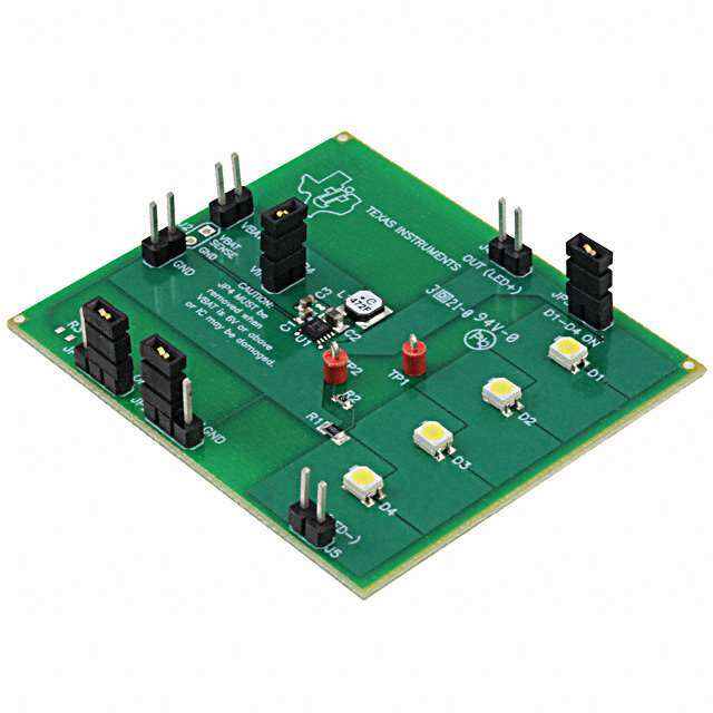
TPS61166EVM-446产品简介:
ICGOO电子元器件商城为您提供TPS61166EVM-446由Texas Instruments设计生产,在icgoo商城现货销售,并且可以通过原厂、代理商等渠道进行代购。 提供TPS61166EVM-446价格参考¥371.66-¥371.66以及Texas InstrumentsTPS61166EVM-446封装/规格参数等产品信息。 你可以下载TPS61166EVM-446参考资料、Datasheet数据手册功能说明书, 资料中有TPS61166EVM-446详细功能的应用电路图电压和使用方法及教程。
| 参数 | 数值 |
| 产品目录 | 编程器,开发系统半导体 |
| 描述 | EVAL MODULE FOR TPS61166-446LED 照明开发工具 TPS61166EVM-446 Eval Mod |
| 产品分类 | |
| 品牌 | Texas Instruments |
| 产品手册 | |
| 产品图片 |
|
| rohs | 否含铅 / 不受限制有害物质指令(RoHS)规范要求限制 |
| 产品系列 | LED 照明开发工具,Texas Instruments TPS61166EVM-446- |
| 数据手册 | 点击此处下载产品Datasheethttp://www.ti.com/lit/pdf/slvu326 |
| 产品型号 | TPS61166EVM-446 |
| 产品 | Evaluation Modules |
| 产品种类 | LED 照明开发工具 |
| 使用的IC/零件 | TPS61166 |
| 其它名称 | 296-31228 |
| 制造商产品页 | http://www.ti.com/general/docs/suppproductinfo.tsp?distId=10&orderablePartNumber=TPS61166EVM-446 |
| 商标 | Texas Instruments |
| 工作电源电压 | 2.5 V to 10 V |
| 工厂包装数量 | 1 |
| 所含物品 | 板 |
| 标准包装 | 1 |
| 核心 | TPS61166 |
| 特性 | 可调光 |
| 用于 | White LEDs |
| 电压-输入 | 2.5 V ~ 6 V |
| 电压-输出 | 17V |
| 电流-输出/通道 | 30mA |
| 相关产品 | /product-detail/zh/TPS61166DSKT/296-25246-2-ND/2175181/product-detail/zh/TPS61166DSKT/296-25246-1-ND/2175184/product-detail/zh/TPS61166DSKT/296-25246-6-ND/2175187/product-detail/zh/TPS61166DSKR/TPS61166DSKR-ND/2232828 |
| 输出和类型 | 1,非隔离 |
| 输出电流 | 30 mA |


- 商务部:美国ITC正式对集成电路等产品启动337调查
- 曝三星4nm工艺存在良率问题 高通将骁龙8 Gen1或转产台积电
- 太阳诱电将投资9.5亿元在常州建新厂生产MLCC 预计2023年完工
- 英特尔发布欧洲新工厂建设计划 深化IDM 2.0 战略
- 台积电先进制程称霸业界 有大客户加持明年业绩稳了
- 达到5530亿美元!SIA预计今年全球半导体销售额将创下新高
- 英特尔拟将自动驾驶子公司Mobileye上市 估值或超500亿美元
- 三星加码芯片和SET,合并消费电子和移动部门,撤换高东真等 CEO
- 三星电子宣布重大人事变动 还合并消费电子和移动部门
- 海关总署:前11个月进口集成电路产品价值2.52万亿元 增长14.8%


PDF Datasheet 数据手册内容提取
User's Guide SLVU326–October2009 TPS61166EVM-446 User's Guide The TPS61166EVM-446 is an evaluation board to assist in evaluating the TPS61166 IC as a WLED driver. Contents 1 Introduction................................................................................................................... 2 2 TPS61166evmElectricalPerformanceSpecifications.................................................................. 3 3 Modifications.................................................................................................................. 4 4 Schematic..................................................................................................................... 4 5 ConnectorandTestPointDescriptions................................................................................... 5 6 TestSetupandResults..................................................................................................... 6 7 EVMAssemblyDrawingsandLayout..................................................................................... 7 ListofFigures 1 TPS61166EVMSchematic ................................................................................................ 4 2 LEDEfficiency ............................................................................................................... 6 3 1kHzPWMDimmingwithD=30%....................................................................................... 6 4 TPS61166EVM-446TopandSilkscreen(ViewedfromTop).......................................................... 7 5 TPS61166EVM-446TopCopper ......................................................................................... 8 6 TPS61166EVM-446BottomLayer........................................................................................ 8 ListofTables 1 TPS61166evmElectricalandPerformanceSpecifications............................................................. 3 2 BillofMaterials............................................................................................................... 9 SLVU326–October2009 TPS61166EVM-446User'sGuide 1 SubmitDocumentationFeedback
Introduction www.ti.com 1 Introduction 1.1 Description TheTPS61166isaboostconverterwitha20-VratedintegratedswitchFETandpowerdiodethatdrives upto5LEDsinseries.ThisdeviceintegratesahighsideswitchFETthatcanturnon/offtheLEDcurrent within1-m softheappliedexternalPWMsignal.Thehighsideswitchalsoprovidesinput-to-outputisolation duringICshutdown. ThedefaultwhiteLEDcurrentissetwiththeexternalsensorresistorR1,andthefeedbackvoltageis regulatedto200-mV,asshowninthetypicalapplicationcircuit.TheLEDcurrentcanbeadjustedusinga pulsewidthmodulation(PWM)signalthroughthePWMpin.TheLEDcurrentissynchronizedtothePWM signal.Thedevicedoesnotdischargetheoutputceramiccapacitorduringdimming,thusreducingaudible noisewhendimming. SeparatingtheICinput(VINpin)andpowerstageinput(VBATpin)makesthedeviceflexibleenoughto supportsingle-ortwo-cellLi-ionbatteryapplications.Otherprotectionfeaturesinclude1.1-Apeak-to-peak overcurrentprotection(OCP),overvoltageprotection(OVP),overloadprotection(OLP),andthermal shutdown.TheTPS61166isavailableina2.5mm· 2.5mmSONpackagewiththermalpad. 1.2 Applications • SmallFormFactorLCDBacklight • MobilePhone • DigitalCamera • PersonalCamcorder • SingleLensReflex 1.3 Features • ICSupplyRange:2.5-Vto6-V • PowerStageInputRange:4.5-Vto10-V • Integrated1.1-A/20-VInternalSwitchFETandPowerDiode • Driveupto5LEDsinSeries • Faston/offLEDCurrentWithin1-m sinBrightnessDimming • BurstPWMDimmingMethodWithFrequencyRangeFrom60-Hzto40-kHz • Built-inSoftStart-up • OverLoadProtection • OverVoltageProtection • 2.5· 2.5· 0.8mmSONPackage 2 TPS61166EVM-446User'sGuide SLVU326–October2009 SubmitDocumentationFeedback
www.ti.com TPS61166evmElectricalPerformanceSpecifications 2 TPS61166evm Electrical Performance Specifications ThespecificationsbelowareforTA=25(cid:176) Cunlessotherwisespecified. Table1.TPS61166evmElectricalandPerformanceSpecifications Parameter Notes&Conditions Min Nom Max Units INPUTCHARACTERISTICS V atJ1 InputVoltage JP4installedtyingV =V 2.5 6 V IN BAT IN V atJ1 InputVoltage JP4removed 4.5 10 V IN V InputUVLO V falling 1.5 1.55 V IN_UVLO IN f PWMdimmingfrequency V <0.3V,1.2V<V <6V 0.06 40 kHz DIM PWML PWMH OUTPUTCHARACTERISTICS I through V =2.5V-10V,EN=PWM=LogicHigh,JP4 29 30 31 OUT LEDcurrent BAT mA JP3 installed V =2.5V-10V,EN=PWM=LogicHigh,JP4 12 17 OUT VoltageatJ4 BAT V installed V =2.5V-10V,EN=PWM=LogicHigh,JP4 18 19 OUT VoltageatJ4 BAT V removed,OVPactive F SwitchingFrequency 1.0 1.2 1.4 MHz SW SLVU326–October2009 TPS61166EVM-446User'sGuide 3 SubmitDocumentationFeedback
Modifications www.ti.com 3 Modifications 3.1 General ToaidusercustomizationoftheEVM,theboardwasdesignedwithdeviceshaving0603orlarger footprints.Arealimplementationlikelyoccupieslesstotalboardspace.Changingcomponentscan improveordegradeEVMperformance.Forexample,addingalargeroutputcapacitorreducesoutput voltageundershootbutlengthensresponsetimeafteraloadtransientevent.Duetotheinternal compensation,theinductorandoutputcapacitorshouldremainwithinthedatasheetlimitsinorderforthe boostconvertertoremaincontrolloopstability. 3.2 Output Voltage TheTPS61166'sLEDcurrentisadjustableandissetbyresistorR1.TochangetheLEDcurrent,theuser shouldconsultthedatasheetonhowtoproperlysizeR1. 3.3 VBAT > 6V TheEVMisshippedwithJP4'sshuntinstalledwhichtiesV toV .IftheEVM'sinputpowersupplyis BAT IN higherthan6V,JP4mustberemovedtopreventtheV pinfrombeingdamaged.WithJP4removed,pin IN 1ofJP1isnolongerpulledup.So,theusermustapplyanexternalvoltagebetween1.2vand6VtoEN (themiddlepinofJP1)inordertoenablethedevice.Alternatively,theusercaninstalla590kW resistoron theR3footprint.ThisresistorandtheinternalpulldownresistoronENformaresistordividerfromV BAT whichprovidesapullupvoltagebetween1.2Vand6Vfor4.5V<V <10V. BAT 4 Schematic Figure1.TPS61166EVMSchematic 4 TPS61166EVM-446User'sGuide SLVU326–October2009 SubmitDocumentationFeedback
www.ti.com ConnectorandTestPointDescriptions 5 Connector and Test Point Descriptions 5.1 J1 –VBAT ThisheaderisthepositiveconnectiontotheinputpowersupplyandistiedtotheICsVBATpin.Theuser mustconnectthepowersupplybetweenJ1andJ3(GND).Theleadstotheinputsupplyshouldbetwisted andkeptasshortaspossible.Theinputvoltagemustbebetween1.6-Vand6-V. 5.2 J2 – VBAT and GND Kelvin Sense Althoughnotinstalled,thisheaderprovidesKelvinsenseconnectionsacrossinputcapacitorC1. 5.3 J3 – GND ThisheaderisthereturnconnectiontotheinputpowersupplyandistiedtotheICsGNDpin.Theuser mustconnectthepowersupplybetweenJ3andJ1(VIN).Theleadstotheinputsupplyshouldbetwisted andkeptasshortaspossible.Theinputvoltagemustbebetween1.6-Vand6-V. 5.4 J4– OUT (LED+) ThisheaderconnectstotheIC'sOUTpin.AfterremovingtheshuntonJP4,theusercanattachtheanode ofanoff-boardLEDstringbetweenthispinandJ5. 5.5 J5– FB (LED-) ThisheaderconnectstotheIC'sFBpin.AfterremovingtheshuntonJP4,theusercanattachthecathode ofanoff-boardLEDstringbetweenthispinandJ4. 5.6 JP1– EN ThemiddlepinofthisjumpertiestotheIC'sENpin.WhenJP4'sshuntisinstalled,placingJP1'sshuntat ONtiesthemiddleENpintoVBAT=VINtherebyturningontheboostconverter.Removingtheshuntfrom thisjumperallowstheIC'sinternalpulldownresistortopullittoground(ormovingtheshunttotheOFF position)therebydisablingtheconverter.WhenJP4'sshuntisnotinstalled,pin1ofJP1isnolonger pulledup.So,theusermustapplyanexternalvoltagebetween1.2vand6VtoEN(themiddlepinofJP1) inordertoenablethedevice.Alternatively,theusercaninstalla590kW resistorontheR3footprint.This resistorandtheinternalpulldownresistoronENformaresistordividerfromV whichprovidesapull BAT upvoltagebetween1.2Vand6Vfor4.5V<V <10V.WithR3installed,theusermustmoveJP1's BAT shunttotheOFFpositioninordertodisabletheconverter. 5.7 JP2 – PWM ThemiddlepinofthisjumpertiestotheIC'sPWMpin.TheusercanapplyanexternalPWMsignalwithin thevoltageandfrequencyrangesspecifiedinTable1tothispintoimplementPWMdimmingoftheLEDs. For100%fullbrightness,theusercanplaceJP2'sshunttotheENpositiontherebytyingthePWMpinto theENpinvoltage.TheusercanalsocompletelydisconnecttheLEDsfromtheboostconverteroutput, therebyturningthemoff,bymovingJP2'sshunttoGND. 5.8 JP3 – D1-D4 ON ThisjumperisinserieswiththeonboardLEDs.Theusercanremovethisjumpersshuntandreplaceit withanammeterinordertomeasuretheLEDcurrent.Theusermustremovethisjumperifoff-board LEDsarebeingconnectedbetweenJ4andJ5. SLVU326–October2009 TPS61166EVM-446User'sGuide 5 SubmitDocumentationFeedback
TestSetupandResults www.ti.com 5.9 TP1 – Test Point 1 ThistestpointconnectstotheIC'sVOpin.SincetheVOpinistheoutputoftheboostconverterbefore theinternalPWMdimmingswitching,theusercanmonitortheboostconverteroutputand,forexample, confirmthattheovervoltageprotectioncircuitproperlyclampstheoutputvoltageiftheLEDsareremoved fromtheoutput. 5.10 TP2 – Test Point 2 ThistestpointcanbeusedtomeasurethesmallsignalcontrolloopgainandphasewithVenable®or similargainphaseanalyzer.Forexample,theuserwouldreplacethe0-W resistorinR2witha49.9-100W resistorbeforeattachingaVenable®gain/phaseanalyzerbetweenheaderJ5andTP2. 6 Test Setup and Results 90 80 70 60 % y - 50 c n e 40 ci Effi 30 D E L 20 10 0 0 5 10 15 20 25 30 ILED - LED Current - mA Figure2.LEDEfficiency Vo-AC = 100 mV/div ILED = 20 mV/div IL= 500 mA/div Time = 200µs/div Figure3.1kHzPWMDimmingwithD=30% 6 TPS61166EVM-446User'sGuide SLVU326–October2009 SubmitDocumentationFeedback
www.ti.com EVMAssemblyDrawingsandLayout 7 EVM Assembly Drawings and Layout Figure4throughFigure6showthedesignofHPA446,theTPS61166EVM'sprintedcircuitboard.The EVMhasbeendesignedusinga2-Layer,1ozcopper-clad,2inchx2inchcircuitboard. Figure4.TPS61166EVM-446TopandSilkscreen(ViewedfromTop) SLVU326–October2009 TPS61166EVM-446User'sGuide 7 SubmitDocumentationFeedback
EVMAssemblyDrawingsandLayout www.ti.com Figure5.TPS61166EVM-446TopCopper Figure6.TPS61166EVM-446BottomLayer 8 TPS61166EVM-446User'sGuide SLVU326–October2009 SubmitDocumentationFeedback
www.ti.com EVMAssemblyDrawingsandLayout 7.1 Bill of Materials Table2liststheEVMcomponentsasconfiguredaccordingtotheschematicshowninFigure1. Table2.BillofMaterials Count RefDes Value Description Size PartNumber MFR 1 C1 4.7m F Capacitor,Ceramic,6.3V,X5R,20% 0603 Std Std 1 C2 0.1m F Capacitor,Ceramic,25V,X5R,20% 0603 Std Std 1 C3 0.1m F Capacitor,Ceramic,6.3V,X5R,20% 0603 Std Std 1 C4 1m F Capacitor,Ceramic,25V,X5R,20% 0603 Std Std 1 C5 1m F Capacitor,Ceramic,6.3V,X5R,20% 0603 Std Std 0 C6 Open Capacitor,Ceramic,6.3V,X5R,20% 0603 Std Std 0 J2,J5,J8 Open Header,Male2-pin,100milspacing 0.100inchx2 PEC02SAAN Sullins 6 J1,J3,J4,J6, PEC02SAAN Header,Male2-pin,100milspacing, 0.100inchx2 PEC02SAAN Sullins J7,J9 1 JP1 PEC02SAAN Header,2-pin,100milspacingInductor, 0.100inchx2 PEC02SAAN Sullins 1 L1 10uH SMT,1.4A,127milliohm 0.189x0.189inch LPS5030-103ML Coilcraft 1 R1 294k Resistor,Chip,1/16W,1% 0603 Std Std 1 R2 10.2k Resistor,Chip,1/16W,1% 0603 Std Std 0 R3 Open Resistor,Chip,1/16W,1% 0603 Std Std 1 R4 0 Resistor,Chip,1/16W,1% 0603 Std Std 1 R5 200k Resistor,Chip,1/16W,1% 0603 Std Std 0 TP1 Open TestPoint,Red,ThruHoleColorKeyed 0.100x0.100inch 5000 Keystone 1 U1 TPS61166DSK IC,LowInputBoostConverterwithIntegrated QFN TPS61166DSK TI PowerDiodeandIsolation SLVU326–October2009 TPS61166EVM-446User'sGuide 9 SubmitDocumentationFeedback
EVALUATIONBOARD/KITIMPORTANTNOTICE TexasInstruments(TI)providestheenclosedproduct(s)underthefollowingconditions: Thisevaluationboard/kitisintendedforuseforENGINEERINGDEVELOPMENT,DEMONSTRATION,OREVALUATIONPURPOSES ONLYandisnotconsideredbyTItobeafinishedend-productfitforgeneralconsumeruse.Personshandlingtheproduct(s)musthave electronicstrainingandobservegoodengineeringpracticestandards.Assuch,thegoodsbeingprovidedarenotintendedtobecomplete intermsofrequireddesign-,marketing-,and/ormanufacturing-relatedprotectiveconsiderations,includingproductsafetyandenvironmental measurestypicallyfoundinendproductsthatincorporatesuchsemiconductorcomponentsorcircuitboards.Thisevaluationboard/kitdoes notfallwithinthescopeoftheEuropeanUniondirectivesregardingelectromagneticcompatibility,restrictedsubstances(RoHS),recycling (WEEE),FCC,CEorUL,andthereforemaynotmeetthetechnicalrequirementsofthesedirectivesorotherrelateddirectives. Shouldthisevaluationboard/kitnotmeetthespecificationsindicatedintheUser’sGuide,theboard/kitmaybereturnedwithin30daysfrom thedateofdeliveryforafullrefund.THEFOREGOINGWARRANTYISTHEEXCLUSIVEWARRANTYMADEBYSELLERTOBUYER ANDISINLIEUOFALLOTHERWARRANTIES,EXPRESSED,IMPLIED,ORSTATUTORY,INCLUDINGANYWARRANTYOF MERCHANTABILITYORFITNESSFORANYPARTICULARPURPOSE. Theuserassumesallresponsibilityandliabilityforproperandsafehandlingofthegoods.Further,theuserindemnifiesTIfromallclaims arisingfromthehandlingoruseofthegoods.Duetotheopenconstructionoftheproduct,itistheuser’sresponsibilitytotakeanyandall appropriateprecautionswithregardtoelectrostaticdischarge. EXCEPTTOTHEEXTENTOFTHEINDEMNITYSETFORTHABOVE,NEITHERPARTYSHALLBELIABLETOTHEOTHERFORANY INDIRECT,SPECIAL,INCIDENTAL,ORCONSEQUENTIALDAMAGES. TIcurrentlydealswithavarietyofcustomersforproducts,andthereforeourarrangementwiththeuserisnotexclusive. TIassumesnoliabilityforapplicationsassistance,customerproductdesign,softwareperformance,orinfringementofpatentsor servicesdescribedherein. PleasereadtheUser’sGuideand,specifically,theWarningsandRestrictionsnoticeintheUser’sGuidepriortohandlingtheproduct.This noticecontainsimportantsafetyinformationabouttemperaturesandvoltages.ForadditionalinformationonTI’senvironmentaland/or safetyprograms,pleasecontacttheTIapplicationengineerorvisitwww.ti.com/esh. NolicenseisgrantedunderanypatentrightorotherintellectualpropertyrightofTIcoveringorrelatingtoanymachine,process,or combinationinwhichsuchTIproductsorservicesmightbeorareused. FCCWarning Thisevaluationboard/kitisintendedforuseforENGINEERINGDEVELOPMENT,DEMONSTRATION,OREVALUATIONPURPOSES ONLYandisnotconsideredbyTItobeafinishedend-productfitforgeneralconsumeruse.Itgenerates,uses,andcanradiateradio frequencyenergyandhasnotbeentestedforcompliancewiththelimitsofcomputingdevicespursuanttopart15ofFCCrules,whichare designedtoprovidereasonableprotectionagainstradiofrequencyinterference.Operationofthisequipmentinotherenvironmentsmay causeinterferencewithradiocommunications,inwhichcasetheuserathisownexpensewillberequiredtotakewhatevermeasuresmay berequiredtocorrectthisinterference. EVMWARNINGSANDRESTRICTIONS ItisimportanttooperatethisEVMwithinthechargeregulationinputvoltagerangeof2.5Vto10Vandtheadapteroutputvoltagerangeof Vinto20V. Exceedingthespecifiedinputrangemaycauseunexpectedoperationand/orirreversibledamagetotheEVM.Iftherearequestions concerningtheinputrange,pleasecontactaTIfieldrepresentativepriortoconnectingtheinputpower. Applyingloadsoutsideofthespecifiedoutputrangemayresultinunintendedoperationand/orpossiblepermanentdamagetotheEVM. PleaseconsulttheEVMUser'sGuidepriortoconnectinganyloadtotheEVMoutput.Ifthereisuncertaintyastotheloadspecification, pleasecontactaTIfieldrepresentative. Duringnormaloperation,somecircuitcomponentsmayhavecasetemperaturesgreaterthan85(cid:176) C.TheEVMisdesignedtooperate properlywithcertaincomponentsabove85(cid:176) Caslongastheinputandoutputrangesaremaintained.Thesecomponentsincludebutare notlimitedtolinearregulators,switchingtransistors,passtransistors,andcurrentsenseresistors.Thesetypesofdevicescanbeidentified usingtheEVMschematiclocatedintheEVMUser'sGuide.Whenplacingmeasurementprobesnearthesedevicesduringoperation, pleasebeawarethatthesedevicesmaybeverywarmtothetouch. MailingAddress:TexasInstruments,PostOfficeBox655303,Dallas,Texas75265 Copyright2007,TexasInstrumentsIncorporated
IMPORTANTNOTICE TexasInstrumentsIncorporatedanditssubsidiaries(TI)reservetherighttomakecorrections,modifications,enhancements,improvements, andotherchangestoitsproductsandservicesatanytimeandtodiscontinueanyproductorservicewithoutnotice.Customersshould obtainthelatestrelevantinformationbeforeplacingordersandshouldverifythatsuchinformationiscurrentandcomplete.Allproductsare soldsubjecttoTI’stermsandconditionsofsalesuppliedatthetimeoforderacknowledgment. TIwarrantsperformanceofitshardwareproductstothespecificationsapplicableatthetimeofsaleinaccordancewithTI’sstandard warranty.TestingandotherqualitycontroltechniquesareusedtotheextentTIdeemsnecessarytosupportthiswarranty.Exceptwhere mandatedbygovernmentrequirements,testingofallparametersofeachproductisnotnecessarilyperformed. TIassumesnoliabilityforapplicationsassistanceorcustomerproductdesign.Customersareresponsiblefortheirproductsand applicationsusingTIcomponents.Tominimizetherisksassociatedwithcustomerproductsandapplications,customersshouldprovide adequatedesignandoperatingsafeguards. TIdoesnotwarrantorrepresentthatanylicense,eitherexpressorimplied,isgrantedunderanyTIpatentright,copyright,maskworkright, orotherTIintellectualpropertyrightrelatingtoanycombination,machine,orprocessinwhichTIproductsorservicesareused.Information publishedbyTIregardingthird-partyproductsorservicesdoesnotconstitutealicensefromTItousesuchproductsorservicesora warrantyorendorsementthereof.Useofsuchinformationmayrequirealicensefromathirdpartyunderthepatentsorotherintellectual propertyofthethirdparty,oralicensefromTIunderthepatentsorotherintellectualpropertyofTI. ReproductionofTIinformationinTIdatabooksordatasheetsispermissibleonlyifreproductioniswithoutalterationandisaccompanied byallassociatedwarranties,conditions,limitations,andnotices.Reproductionofthisinformationwithalterationisanunfairanddeceptive businesspractice.TIisnotresponsibleorliableforsuchaltereddocumentation.Informationofthirdpartiesmaybesubjecttoadditional restrictions. ResaleofTIproductsorserviceswithstatementsdifferentfromorbeyondtheparametersstatedbyTIforthatproductorservicevoidsall expressandanyimpliedwarrantiesfortheassociatedTIproductorserviceandisanunfairanddeceptivebusinesspractice.TIisnot responsibleorliableforanysuchstatements. TIproductsarenotauthorizedforuseinsafety-criticalapplications(suchaslifesupport)whereafailureoftheTIproductwouldreasonably beexpectedtocauseseverepersonalinjuryordeath,unlessofficersofthepartieshaveexecutedanagreementspecificallygoverning suchuse.Buyersrepresentthattheyhaveallnecessaryexpertiseinthesafetyandregulatoryramificationsoftheirapplications,and acknowledgeandagreethattheyaresolelyresponsibleforalllegal,regulatoryandsafety-relatedrequirementsconcerningtheirproducts andanyuseofTIproductsinsuchsafety-criticalapplications,notwithstandinganyapplications-relatedinformationorsupportthatmaybe providedbyTI.Further,BuyersmustfullyindemnifyTIanditsrepresentativesagainstanydamagesarisingoutoftheuseofTIproductsin suchsafety-criticalapplications. TIproductsareneitherdesignednorintendedforuseinmilitary/aerospaceapplicationsorenvironmentsunlesstheTIproductsare specificallydesignatedbyTIasmilitary-gradeor"enhancedplastic."OnlyproductsdesignatedbyTIasmilitary-grademeetmilitary specifications.BuyersacknowledgeandagreethatanysuchuseofTIproductswhichTIhasnotdesignatedasmilitary-gradeissolelyat theBuyer'srisk,andthattheyaresolelyresponsibleforcompliancewithalllegalandregulatoryrequirementsinconnectionwithsuchuse. TIproductsareneitherdesignednorintendedforuseinautomotiveapplicationsorenvironmentsunlessthespecificTIproductsare designatedbyTIascompliantwithISO/TS16949requirements.Buyersacknowledgeandagreethat,iftheyuseanynon-designated productsinautomotiveapplications,TIwillnotberesponsibleforanyfailuretomeetsuchrequirements. FollowingareURLswhereyoucanobtaininformationonotherTexasInstrumentsproductsandapplicationsolutions: Products Applications Amplifiers amplifier.ti.com Audio www.ti.com/audio DataConverters dataconverter.ti.com Automotive www.ti.com/automotive DLP®Products www.dlp.com Broadband www.ti.com/broadband DSP dsp.ti.com DigitalControl www.ti.com/digitalcontrol ClocksandTimers www.ti.com/clocks Medical www.ti.com/medical Interface interface.ti.com Military www.ti.com/military Logic logic.ti.com OpticalNetworking www.ti.com/opticalnetwork PowerMgmt power.ti.com Security www.ti.com/security Microcontrollers microcontroller.ti.com Telephony www.ti.com/telephony RFID www.ti-rfid.com Video&Imaging www.ti.com/video RF/IFandZigBee®Solutions www.ti.com/lprf Wireless www.ti.com/wireless MailingAddress:TexasInstruments,PostOfficeBox655303,Dallas,Texas75265 Copyright©2009,TexasInstrumentsIncorporated