ICGOO在线商城 > TPS61052YZGT
 Datasheet下载
- 型号: TPS61052YZGT
- 制造商: Texas Instruments
- 库位|库存: xxxx|xxxx
- 要求:
| 数量阶梯 | 香港交货 | 国内含税 |
| +xxxx | $xxxx | ¥xxxx |
查看当月历史价格
查看今年历史价格
TPS61052YZGT产品简介:
ICGOO电子元器件商城为您提供TPS61052YZGT由Texas Instruments设计生产,在icgoo商城现货销售,并且可以通过原厂、代理商等渠道进行代购。 提供TPS61052YZGT价格参考以及Texas InstrumentsTPS61052YZGT封装/规格参数等产品信息。 你可以下载TPS61052YZGT参考资料、Datasheet数据手册功能说明书, 资料中有TPS61052YZGT详细功能的应用电路图电压和使用方法及教程。
| 参数 | 数值 |
| 产品目录 | 集成电路 (IC)光电子产品 |
| 描述 | IC LED DRVR PHOTO FLASH 12-DSBGALED照明驱动器 1.2A High Pwr White LED Driver |
| 产品分类 | |
| 品牌 | Texas Instruments |
| 产品手册 | |
| 产品图片 |
|
| rohs | 符合RoHS无铅 / 符合限制有害物质指令(RoHS)规范要求 |
| 产品系列 | LED照明电子器件,LED照明驱动器,Texas Instruments TPS61052YZGT- |
| 数据手册 | |
| 产品型号 | TPS61052YZGT |
| 产品目录页面 | |
| 产品种类 | LED照明驱动器 |
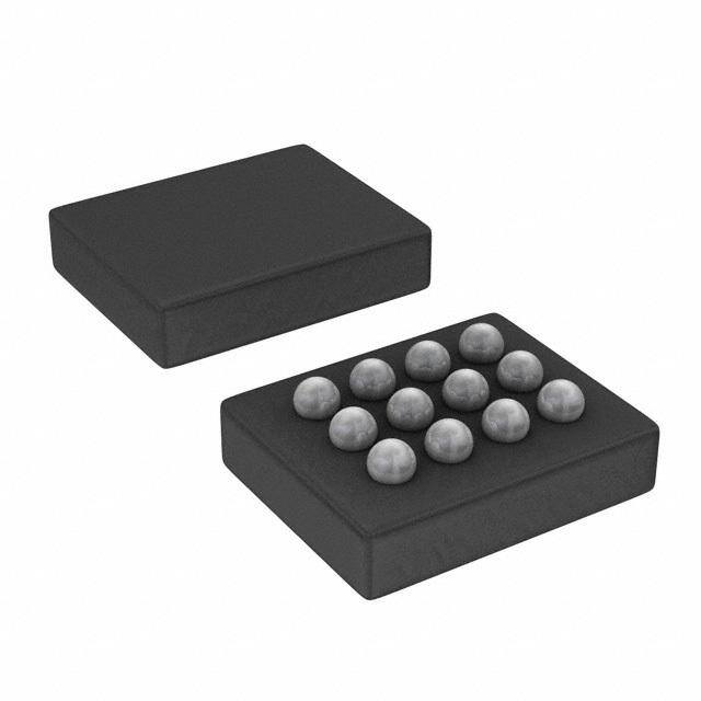
| 供应商器件封装 | 12-DSBGA(1.53x1.98) |
| 其它名称 | 296-21897-1 |
| 内部驱动器 | 是 |
| 包装 | 剪切带 (CT) |
| 商标 | Texas Instruments |
| 安装类型 | 表面贴装 |
| 安装风格 | SMD/SMT |
| 封装 | Reel |
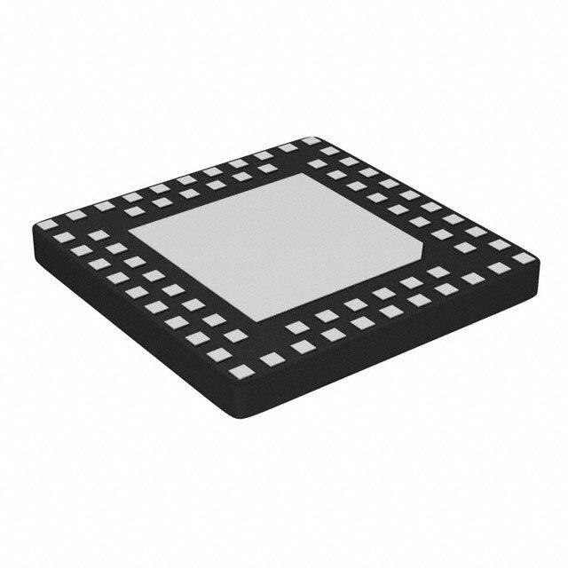
| 封装/外壳 | 12-UFBGA,DSBGA |
| 封装/箱体 | DSBGA-12 |
| 工作温度 | -40°C ~ 85°C |
| 工作频率 | 2 MHz |
| 工厂包装数量 | 250 |
| 恒压 | - |
| 恒流 | 是 |
| 拓扑 | PWM,升压(升压) |
| 拓扑结构 | Boost |
| 最大工作温度 | + 85 C |
| 最大电源电流 | 8.5 mA |
| 最小工作温度 | - 40 C |
| 标准包装 | 1 |
| 电压-电源 | 2.5 V ~ 6 V |
| 电压-输出 | 5.5V |
| 类型 | Inductive |
| 类型-初级 | 闪灯/白光 |
| 类型-次级 | 白色 LED |
| 系列 | TPS61052 |
| 输入电压 | 2.5 V to 6 V |
| 输出数 | 1 |
| 输出电流 | 1.2 A |
| 输出端数量 | 1 Output |
| 输出类型 | Constant Current |
| 配用 | /product-detail/zh/TPS61052EVM-269/296-31219-ND/1907962 |
| 频率 | 1.8MHz ~ 2.2MHz |


.jpg)


- 商务部:美国ITC正式对集成电路等产品启动337调查
- 曝三星4nm工艺存在良率问题 高通将骁龙8 Gen1或转产台积电
- 太阳诱电将投资9.5亿元在常州建新厂生产MLCC 预计2023年完工
- 英特尔发布欧洲新工厂建设计划 深化IDM 2.0 战略
- 台积电先进制程称霸业界 有大客户加持明年业绩稳了
- 达到5530亿美元!SIA预计今年全球半导体销售额将创下新高
- 英特尔拟将自动驾驶子公司Mobileye上市 估值或超500亿美元
- 三星加码芯片和SET,合并消费电子和移动部门,撤换高东真等 CEO
- 三星电子宣布重大人事变动 还合并消费电子和移动部门
- 海关总署:前11个月进口集成电路产品价值2.52万亿元 增长14.8%

PDF Datasheet 数据手册内容提取
Product Sample & Technical Tools & Support & Folder Buy Documents Software Community TPS61050,TPS61052 SLUS525A–MARCH2007–REVISEDSEPTEMBER2015 TPS6105x 1.2-A High-Power White LED Driver 2 2-MHz Synchronous Boost Converter With I C Compatible Interface 1 Features 3 Description • FourOperationalModes The TPS6105x device is based on a high-frequency 1 synchronous-boost topology with constant current – TorchandFlashuptoI =1200mA LED sink to drive single white LEDs. The device uses an – Voltage-RegulatedBoostConverter:4.5V,5 inductive fixed-frequency PWM control scheme using V,and5.25V small external components, minimizing input ripple current. – Shutdown:0.3 μA(Typical) • TotalSolutionCircuitArea <25mm2 The 2-MHz switching frequency allows the use of small and low profile 2.2-μH inductors. To optimize • Upto96%Efficiency overall efficiency, the device operates with only a • I2C-CompatibleInterfaceupto400kbps 250-mVLEDfeedbackvoltage. • IntegratedLEDTurnonSafetyTimer The TPS6105x device not only operates as a • ZeroLatencyTX-MaskingInput(TPS61050) regulated current source, but also as a standard • HardwareVoltageModeSelectionInput voltage-boost regulator. This additional operating (TPS61052) mode can be useful to supply other high-power devices in the system, such as a hands-free audio • IntegratedADCforLEDV Monitoring F power amplifier, or any other component requiring a • IntegratedLowLightDimmingMode supply voltage higher than the battery voltage (refer • LEDDisconnectDuringShutdown toTPS61052). • OpenandShortedLEDProtection For highest flexibility, the LED current or the desired • OvertemperatureProtection output voltage can be programmed through an I2C • Availableina12-Pin NanoFree™(CSP)and compatible interface. To simplify flash synchronization with the camera module, the device 10-PinQFNPackaging offers a trigger pin (FLASH_SYNC) for fast LED turnontime. 2 Applications When the TPS6105x is not in use, it can be put into • CameraWhiteLEDTorch/FlashforCellPhones, shutdown mode through the I2C-compatible interface, Smart-PhonesandPDAs reducing the input current to 0.3 μA (typical). During • AudioAmplifierPowerSupply shutdown, the LED pin is high impedance to avoid leakagecurrentthroughtheLED. TypicalApplicationSchematic DeviceInformation(1) TPS61050 L PARTNUMBER PACKAGE BODYSIZE(NOM) SW SW VOUT TPS61050 VSON(10) 3.00mm×3.00mm 2.2mH AVIN COUT TPS61052 DSBGA(12) 1.96mm×1.46mm 10mF C P (1) For all available packages, see the orderable addendum at IN theendofthedatasheet. P P LED I2C I/F SCL SDA GPIO FLASH_SYNC PGND P AGND PGND 1 An IMPORTANT NOTICE at the end of this data sheet addresses availability, warranty, changes, use in safety-critical applications, intellectualpropertymattersandotherimportantdisclaimers.PRODUCTIONDATA.
TPS61050,TPS61052 SLUS525A–MARCH2007–REVISEDSEPTEMBER2015 www.ti.com Table of Contents 1 Features.................................................................. 1 7.5 Programming...........................................................20 2 Applications........................................................... 1 7.6 RegisterMaps.........................................................24 3 Description............................................................. 1 8 ApplicationandImplementation........................ 29 4 RevisionHistory..................................................... 2 8.1 ApplicationInformation............................................29 8.2 TypicalApplications................................................29 5 PinConfigurationandFunctions......................... 3 9 PowerSupplyRecommendations...................... 38 6 Specifications......................................................... 4 10 Layout................................................................... 38 6.1 AbsoluteMaximumRatings......................................4 6.2 ESDRatings..............................................................4 10.1 LayoutGuidelines.................................................38 6.3 RecommendedOperatingConditions.......................4 10.2 LayoutExample....................................................38 6.4 ThermalInformation..................................................4 10.3 ThermalConsiderations........................................38 6.5 ElectricalCharacteristics...........................................5 11 DeviceandDocumentationSupport................. 40 6.6 I2CInterfaceTimingCharacteristics ........................6 11.1 DeviceSupport......................................................40 6.7 TypicalCharacteristics..............................................8 11.2 RelatedLinks........................................................40 7 DetailedDescription............................................ 11 11.3 Trademarks...........................................................40 7.1 Overview.................................................................11 11.4 ElectrostaticDischargeCaution............................40 7.2 FunctionalBlockDiagram.......................................12 11.5 Glossary................................................................40 7.3 FeatureDescription.................................................14 12 Mechanical,Packaging,andOrderable Information........................................................... 40 7.4 DeviceFunctionalModes........................................15 12.1 PackageSummary................................................40 4 Revision History ChangesfromOriginal(March2007)toRevisionA Page • AddedPinConfigurationandFunctionssection,ESDRatingstable,FeatureDescriptionsection,DeviceFunctional Modes,ApplicationandImplementationsection,PowerSupplyRecommendationssection,Layoutsection,Device andDocumentationSupportsection,andMechanical,Packaging,andOrderableInformationsection .............................. 1 • Updatednamesofthepinoutdrawingstoreflectthenewstandards.................................................................................... 3 • DeletedDissipationRatingstable........................................................................................................................................... 4 2 SubmitDocumentationFeedback Copyright©2007–2015,TexasInstrumentsIncorporated ProductFolderLinks:TPS61050 TPS61052
TPS61050,TPS61052 www.ti.com SLUS525A–MARCH2007–REVISEDSEPTEMBER2015 5 Pin Configuration and Functions DRCPackage 10-PinVSON YZGPackage TopView 12-PinDSBGA TopView YZGPackage 12-PinDSBGA BottomView PinFunctions PIN I/O DESCRIPTION NAME VSON DSBGA AVIN 5 D3 I Thisistheinputvoltagepinofthedevice.Connectdirectlytotheinputbypasscapacitor. VOUT 9 A2 O Boostconverteroutput. LEDreturninput.ThisfeedbackpinregulatestheLEDcurrentthroughtheinternalsense LED 6 D2 I resistorbyregulatingthevoltageacrossit.Theregulationoperateswithtypically250mV dropoutvoltage.ConnecttothecathodeoftheLED. Flashstrobepulsesynchronizationinput. FLASH_SYNC=LOW(GND):ThedeviceisoperatingandregulatingtheLEDcurrenttothe FLASH_SYNC 10 A1 I torchcurrentlevel(TC). FLASH_SYNC=HIGH(VIN):ThedeviceisoperatingandregulatingtheLEDcurrenttothe flashcurrentlevel(FC). SCL 2 B3 I Serialinterfaceclockline.Thispinmustnotbeleftfloatingandmustbeterminated. SDA 1 A3 I/O Serialinterfaceaddress/dataline.Thispinmustnotbeleftfloatingandmustbeterminated. Generalpurposeinput/output(refertoREGISTER2).Thispincaneitherbeconfiguredasa GPIO 3 C3 I/O logicinputorasanopen-drainoutput(TPS61050). ENVM 3 C3 I Enablepinforvoltagemodeboostconverter(TPS61052). Inductorconnection.DrainoftheinternalpowerMOSFET.Connecttotheswitchedsideof SW 8 B1,B2 I/O theinductor.SWishighimpedanceduringshutdown. PGND 7 C1,C2 — Powerground.ConnecttoAGNDunderneathIC. AGND 4 D1 — Analogground. PowerPAD™ — — — InternallyconnectedtoPGND. Copyright©2007–2015,TexasInstrumentsIncorporated SubmitDocumentationFeedback 3 ProductFolderLinks:TPS61050 TPS61052
TPS61050,TPS61052 SLUS525A–MARCH2007–REVISEDSEPTEMBER2015 www.ti.com 6 Specifications 6.1 Absolute Maximum Ratings overoperatingfree-airtemperaturerange(unlessotherwisenoted)(1) MIN MAX UNIT VoltageonAVIN,VOUT,SW,LED (2) –0.3 7 V VoltageonSCL,SDA,FLASH_SYNC,GPIO,ENVM (2) –0.3 7 V InputcurrentonGPIO 25 mA T Operatingambienttemperature (3) –40 85 °C A T Maximumoperatingjunctiontemperature 150 °C J(MAX) T Storagetemperature –65 150 °C stg (1) StressesbeyondthoselistedunderAbsoluteMaximumRatingsmaycausepermanentdamagetothedevice.Thesearestressratings only,whichdonotimplyfunctionaloperationofthedeviceattheseoranyotherconditionsbeyondthoseindicatedunderRecommended OperatingConditions.Exposuretoabsolute-maximum-ratedconditionsforextendedperiodsmayaffectdevicereliability. (2) Allvoltagevaluesarewithrespecttonetworkgroundterminal. (3) Inapplicationswherehighpowerdissipationand/orpoorpackagethermalresistanceispresent,themaximumambienttemperaturemay havetobederated.Maximumambienttemperature(T )isdependentonthemaximumoperatingjunctiontemperature(T ),the A(max) J(max) maximumpowerdissipationofthedeviceintheapplication(P ),andthejunction-to-ambientthermalresistanceofthepart/package D(max) intheapplication(θ ),asgivenbythefollowingequation:T =T –(θ ×P ). JA A(max) J(max) JA D(max) 6.2 ESD Ratings VALUE UNIT Humanbodymodel(HBM),perANSI/ESDA/JEDECJS-001(1) ±2000 Charged-devicemodel(CDM),perJEDECspecificationJESD22- V(ESD) Electrostaticdischarge C101(2) ±1000 V Machinemodel(MM) ±200 (1) JEDECdocumentJEP155statesthat500-VHBMallowssafemanufacturingwithastandardESDcontrolprocess. (2) JEDECdocumentJEP157statesthat250-VCDMallowssafemanufacturingwithastandardESDcontrolprocess. 6.3 Recommended Operating Conditions overoperatingfree-airtemperaturerange(unlessotherwisenoted) MIN NOM MAX UNIT V Inputvoltagerange 2.5 3.6 6 V IN OutputvoltagerangeinCurrentregulatormode V 5.5 IN V V OUT OutputvoltagerangeinVoltageregulatormode 4.5 5.25 L Inductanceeffectivevaluerange 1.3 2.2 2.9 V C Inputcapacitancerange 10 µH IN C Outputcapacitanceeffectivevaluerange 3 10 50 µF OUT T Operatingjunctiontemperature –40 125 J 6.4 Thermal Information TPS6105x THERMALMETRIC(1) DRC(VSON) YZG(DSBGA) UNIT 10PINS 12PINS R Junction-to-ambientthermalresistance 48.5 82 °C/W θJA R Junction-to-case(top)thermalresistance 67.4 0.6 °C/W θJC(top) R Junction-to-boardthermalresistance 23 35 °C/W θJB ψ Junction-to-topcharacterizationparameter 1.8 2.6 °C/W JT ψ Junction-to-boardcharacterizationparameter 23.1 19.1 °C/W JB R Junction-to-case(bottom)thermalresistance 5.3 N/A °C/W θJC(bot) (1) Formoreinformationabouttraditionalandnewthermalmetrics,seetheSemiconductorandICPackageThermalMetricsapplication report,SPRA953. 4 SubmitDocumentationFeedback Copyright©2007–2015,TexasInstrumentsIncorporated ProductFolderLinks:TPS61050 TPS61052
TPS61050,TPS61052 www.ti.com SLUS525A–MARCH2007–REVISEDSEPTEMBER2015 6.5 Electrical Characteristics UnlessotherwisenotedthespecificationappliesforV =3.6Voveranoperatingjunctiontemp.of–40°C≤T ≤125°C. IN J TypicalvaluesareforT =25°C. A PARAMETER TESTCONDITIONS MIN TYP MAX UNIT SUPPLYCURRENT Inputvoltage 2.5 6 V VIN Minimuminputvoltageforstart-up MODE_CTRL[1:0]=11,OV[1:0]=01,RL=10Ω 2.5 V IQ OperatingquiescentcurrentintoAVIN MODE_CTRL[1:0]=01,ILED=0mA 8.5 mA MODE_CTRL[1:0]=00,OV[1:0]≠11 0.3 3 μA –40°C≤TJ≤85°C ISD ShutdowncurrentintoAVIN MODE_CTRL[1:0]=00,OV[1:0]=11 140 μA –40°C≤TJ≤85°C VUVLO Undervoltagelockoutthreshold VINfalling 2.3 2.4 V OUTPUT Currentregulatormode VIN 5.5 VOUT Outputvoltage V Voltageregulatormode 4.5 5.25 OVPOutputovervoltageprotection VOUTrising 5.7 6 6.25 V OVP Outputovervoltageprotectionhysterisis 0.15 V D Minimumdutycycle 7.5% 0.25V≤VLED≤2V, –15% 15% LEDcurrentaccuracy(1) 50mA≤ILED ≤250mA,TJ=50°C 0.25V≤VLED ≤2V, –12% 12% 200mA≤ILED ≤1200mA,TJ=50°C LEDcurrenttemperaturecoefficient 0.08 %/°C DCoutputvoltageaccuracy 2.5V≤VIN≤0.9VOUT,PWMoperation –3% 3% VLED LEDsensevoltage ILED=1200mA 250 mV LEDinputleakagecurrent VLED=VOUT=5V,–40°C≤TJ≤85°C 0.1 1 μA POWERSWITCH SwitchMOSFETon-resistance 80 rDS(on) VOUT=VGS=3.6V mΩ RectifierMOSFETon-resistance 80 SwitchMOSFETleakage 0.1 1 Ilkg(SW) VDS=6V,–40°C≤TJ≤85°C μA RectifierMOSFETleakage 0.1 1 2.5V≤VIN ≤6V,ILIMbits=00 850 1000 1150 Ilim Switchcurrentlimit 2.5V≤VIN ≤6V,ILIMbits=01,10(1) 1275 1500 1725 mA 2.5V≤VIN ≤6V,ILIMbits=11(1) 1700 2000 2300 Thermalshutdown(1) 140 160 °C Thermalshutdownhysteresis(1) 20 °C OSCILLATOR fSW Oscillatorfrequency 1.8 2 2.2 MHz ADC Resolution 3 Bits Totalerror(1) VLED=0.25V,assuredmonotonicbydesign ±0.25 ±1 LSB SDA,SCL,GPIO,ENVM,FLASH_SYNC V(IH) High-levelinputvoltage 1.2 V V(IL) Low-levelinputvoltage 0.4 V Low-leveloutputvoltage(SDA) IOL=8mA 0.3 V(OL) V Low-leveloutputvoltage(GPIO) DIR=1,IOL=8mA 0.3 I(LKG) Logicinputleakagecurrent InputconnectedtoVINorGND,–40°C≤TJ ≤85°C 0.01 0.1 μA GPIOpulldownresistance DIR=0,GPIO≤0.4V(TPS61050) 400 kΩ ENVMpulldownresitance ENVM≤0.4V(TPS61052) 400 kΩ FLASH_SYNCpulldownresistance FLASH_SYNC≤0.4V 400 kΩ (1) Assuredbydesign.Nottestedinproduction. Copyright©2007–2015,TexasInstrumentsIncorporated SubmitDocumentationFeedback 5 ProductFolderLinks:TPS61050 TPS61052
TPS61050,TPS61052 SLUS525A–MARCH2007–REVISEDSEPTEMBER2015 www.ti.com Electrical Characteristics (continued) UnlessotherwisenotedthespecificationappliesforV =3.6Voveranoperatingjunctiontemp.of–40°C≤T ≤125°C. IN J TypicalvaluesareforT =25°C. A PARAMETER TESTCONDITIONS MIN TYP MAX UNIT TIMING FromshutdownintotorchmodeILED=75mA 1.2 ms Start-uptime FromshutdownintovoltagemodethroughENVM 650 μs IOUT=0mA LEDcurrentsettlingtime(2)triggeredby MODE_CTRL[1:0]=10, 400 μs risingedgeonFLASH_SYNC ILED=from0mAto900mA LEDcurrentsettlingtime(2)triggeredby MODE_CTRL[1:0]=10, 20 μs TXmask ILED=900mAto150mA (2) Settlingtimeto±15%ofthetargetvalue 6.6 I2C Interface Timing Characteristics(1) MIN TYP MAX UNIT Standardmode 100 f SCLclockfrequency kHz SCL Fastmode 400 Standardmode 4.7 t BusfreetimebetweenaSTOPandSTARTcondition μs BUF Fastmode 1.3 Standardmode 4 μs t ;t Holdtime(repeated)STARTcondition HD STA Fastmode 600 ns Standardmode 4.7 t LOWperiodoftheSCLclock μs LOW Fastmode 1.3 Standardmode 4 μs t HIGHperiodoftheSCLclock HIGH Fastmode 600 ns Standardmode 4.7 μs t ;t SetuptimeforarepeatedSTARTcondition SU STA Fastmode 600 ns Standardmode 250 t ;t Datasetuptime ns SU DAT Fastmode 100 Standardmode 0 3.45 t ;t Dataholdtime μs HD DAT Fastmode 0 0.9 Standardmode 20+0.1C 1000 B t RisetimeofSCLsignal ns RCL Fastmode 20+0.1C 300 B RisetimeofSCLsignalafterarepeatedSTARTcondition Standardmode 20+0.1CB 1000 t ns RCL1 andafteranacknowledgebit Fastmode 20+0.1C 1000 B Standardmode 20+0.1C 300 B t FalltimeofSCLsignal ns FCL Fastmode 20+0.1C 300 B Standardmode 20+0.1C 1000 B t RisetimeofSDAsignal ns RDA Fastmode 20+0.1C 300 B Standardmode 20+0.1C 300 B t FalltimeofSDAsignal ns FDA Fastmode 20+0.1C 300 B Standardmode 4 μs t ;t SetuptimeforSTOPcondition SU STO Fastmode 600 ns C CapacitiveloadforSDAandSCL 400 pF B (1) Assuredbydesign.Nottestedinproduction. 6 SubmitDocumentationFeedback Copyright©2007–2015,TexasInstrumentsIncorporated ProductFolderLinks:TPS61050 TPS61052
TPS61050,TPS61052 www.ti.com SLUS525A–MARCH2007–REVISEDSEPTEMBER2015 SDA tf tLOW tr tsu;DAT tf thd;STA tr tBUF SCL thd;STA tsu;STA tsu;STO S thd;DAT HIGH Sr P S Figure1. SerialInterfaceTimingForF/S-Mode Copyright©2007–2015,TexasInstrumentsIncorporated SubmitDocumentationFeedback 7 ProductFolderLinks:TPS61050 TPS61052
TPS61050,TPS61052 SLUS525A–MARCH2007–REVISEDSEPTEMBER2015 www.ti.com 6.7 Typical Characteristics Table1.TableofGraphs GRAPHTITLE FIGURE LEDPowerEfficiency vsInputVoltage Figure2,Figure3 DCInputCurrent vsInputVoltage Figure4 LEDCurrent vsLEDPinHeadroomVoltage Figure5 LEDCurrent vsLEDCurrentDigitalCode Figure6,Figure7,Figure8 VoltageModeEfficiency vsOutputCurrent Figure9 DCOutputVoltage vsLoadCurrent Figure10 DCOutputVoltage vsInputVoltage Figure11 QuiescentCurrent vsInputVoltage Figure12 ShutdownCurrent vsInputVoltage Figure13 JunctionTemperature vsGPIOVoltage Figure14 100 100 90 ILED= 250 mA 90 ILED= 1200 mA D/PIN) - % 7800 ILED= 150 mILAED= 100 mA D/PIN) - % 7800 ILED= 300 mA E E cy (PL 60 ILED= 50 mA cy (PL 60 ILED= I5L0E0D m=A 700 mA cien 50 cien 50 ILED= 900 mA Effi 40 Effi 40 er er w 30 w 30 o o P P ED 20 ED 20 L L 10 ILIM= 2000 mA 10 ILIM =2000 mA 0 0 2.5 2.9 3.3 3.7 4.1 4.5 4.9 5.3 5.5 2.5 2.9 3.3 3.7 4.1 4.5 4.9 5.3 5.5 VI- Input Voltage - V VI- Input Voltage - V Figure2.LEDPowerEfficiencyvsInputVoltage Figure3.LEDPowerEfficiencyvsInputVoltage 2500 1400 ILIM= 2000 mA ILIM= 2000 mA ILED= 1200 mA 2250 ILED= 700 mA 1200 2000 A 1750 ILED= 900 mA 1000 ILED= 900 mA m C Input Current - 111025050000 ILED= 1200 mA LED Current - mA 680000 IILLEEDD== 570000 mmAA D 750 400 500 200 ILED= 150 mA ILED= 75 mA 250 ILED= 500 mA ILED= 300 mA 0 0 2.5 2.9 3.3 3.7 4.1 4.5 4.9 5.3 5.5 250 350 450 550 650 750 850 950 1050 VI- Input Voltage - V LED Pin Headroom Voltage - mV Figure4.DCInputCurrentvsInputVoltage Figure5.LEDCurrentvsLEDPinHeadroomVoltage 8 SubmitDocumentationFeedback Copyright©2007–2015,TexasInstrumentsIncorporated ProductFolderLinks:TPS61050 TPS61052
TPS61050,TPS61052 www.ti.com SLUS525A–MARCH2007–REVISEDSEPTEMBER2015 300 1300 280 ILIM= 2000 mA 1200 ILIM= 2000 mA VIN= 4.5 V 260 VIN= 4.5 V 1100 VIN= 3.6 V 240 VIN= 3.6 V 1000 220 LED Current - mA 111112024680000000 VIN= 2.5 V LED Current - mA 456789000000000000 VIN= 2.5 V 80 300 60 200 40 20 100 0 0 0 40 80 120 160 200 240 280300 0 200 400 600 800 1000 12001300 LED Current Digital Code - mA LED Current Digital Code - mA Figure6.LEDCurrentvsLEDCurrentDigitalCode Figure7.LEDCurrentvsLEDCurrentDigitalCode 1300 100 1200 ILIM= 2000 mA TA= 85°C 90 VIN= 4.2 V 1100 1000 80 VIN= 3.6 V 900 70 VIN= 3 V ED Current - mA 567800000000 TA= -T4A0°=C 25°C Efficiency - % 456000 VIN= 2.5 V L 400 30 300 20 120000 10 VILOIMUT= =2 050 V0, mA 0 0 0 200 400 600 800 1000 12001300 0 1 10 100 1000 10000 LED Current Digital Code - mA IO- Output Current - mA Figure8.LEDCurrentvsLEDCurrentDigitalCode Figure9.VoltageModeEfficiencyvsLoadCurrent 5.15 5.60 VILOIMUT= =2 050 V0, mA 5.50 VILOIMUT= =2 050 V0, mA IOUT= 0 mA 5.10 5.40 IOUT= 100 mA V ut Voltage - V 5.055 VIN= 4.2 V put Voltage - 55..2300 IOUT= 1000 mA DC Outp 4.95 VIVNIN= =3 .36 VV DC Out 5.10 5 VIN= 2.5 V 4.90 4.90 4.80 4.85 0.1 1 10 100 1000 10000 2.5 2.9 3.3 3.7 4.1 4.5 4.9 5.35.5 IO- Output Current - mA VI- Input Voltage - V Figure10.DCOutputVoltagevsOutputCurrent Figure11.DCOutputVoltagevsInputVoltage Copyright©2007–2015,TexasInstrumentsIncorporated SubmitDocumentationFeedback 9 ProductFolderLinks:TPS61050 TPS61052
TPS61050,TPS61052 SLUS525A–MARCH2007–REVISEDSEPTEMBER2015 www.ti.com 15 1.40 14 Voltage Mode Regulation, 13 VO= 5 V 1.20 TA= 85°C 12 Current - mA 110891 n Current -Am 0.801 uiescent 567 Shutdow 0.60 TA= 25°C Q 4 0.40 3 2 0.20 TA= -40°C 1 0 0 2.5 2.9 3.3 3.7 4.1 4.5 4.9 5.35.5 2.5 2.9 3.3 3.7 4.1 4.5 4.9 5.35.5 VI- Input Voltage - V VI- Input Voltage - V Figure12.QuiescentCurrentvsInputVoltage Figure13.ShutdownCurrentvsInputVoltage 200 GPIO = Input, 175 IGPIO= -100mA C 150 ure - ° 125 at er 100 p m Te 75 n ctio 50 n Ju 25 - TJ 0 InpGutP BIOuffer -25 VGPIO 100mA -50 -0.50 -0.45 -0.40 -0.35 -0.30 -0.25 -0.20 GPIO Voltage - V Figure14.JunctionTemperaturevsGPIOVoltage 10 SubmitDocumentationFeedback Copyright©2007–2015,TexasInstrumentsIncorporated ProductFolderLinks:TPS61050 TPS61052
TPS61050,TPS61052 www.ti.com SLUS525A–MARCH2007–REVISEDSEPTEMBER2015 7 Detailed Description 7.1 Overview The TPS6105x family employs a 2-MHz constant-frequency, current-mode PWM converter to generate the output voltage required to drive high-power LEDs. The device integrates a power stage based on an NMOS switch and a synchronous NMOS rectifier. The device also implements a linear low-side current regulator to controltheLEDcurrentwhenthebatteryvoltageishigherthanthediodeforwardvoltage. In boost mode, the duty cycle of the converter is set by the error amplifier and the saw-tooth ramp applied to the comparator. Because the control architecture is based on a current-mode control, a compensation ramp is added to allow stable operation at duty cycles larger than 50%. The converter is a fully-integrated synchronous-boost converter, always operating in continuous-conduction mode. This allows low-noise operation, and avoids ringing ontheswitchpin,whichwouldbeseenonaconverterwhenenteringdiscontinuous-conductionmode. The TPS6105x device not only operates as a regulated current source but also as a standard voltage-boost regulator. In the TPS61052 device, the voltage-mode operation can be activated either by a software command or by means of a hardware signal (ENVM). This additional operating mode can be useful to properly synchronize the converter when supplying other high-power devices in the system, such as a hands-free audio power amplifier,oranyothercomponentrequiringasupplyvoltagehigherthanthebatteryvoltage. The TPS6105x integrates an I2C-compatible interface, allowing transfers up to 400 kbps. This communication interfacecanbeusedto • settheoperatingmode(shutdown,constantoutputcurrentmodevs.constantoutputvoltagemode). • controlthebrightnessoftheexternalLED(torchandflashmodes). • adjusttheoutputvoltage(4.5V/5V/5.25V)ortoprogramthesafetytimer. Formoredetails,refertotheI2CRegisterDescriptionsection. The torch and flash functions can be controlled by the I2C interface. To simplify flash synchronization with the camera module, the device offers a FLASH_SYNC strobe input pin to switch (with zero latency) the LED current from flash to torch light. The maximum duration of the flash pulse can be limited by means of an internal user- programmablesafetytimer(STIM). Copyright©2007–2015,TexasInstrumentsIncorporated SubmitDocumentationFeedback 11 ProductFolderLinks:TPS61050 TPS61052
TPS61050,TPS61052 SLUS525A–MARCH2007–REVISEDSEPTEMBER2015 www.ti.com 7.2 Functional Block Diagram AVIN SW Undervoltage Lockout Bias Supply VREF= 1.22 V Ramp OVP REF Bandgap Compensation COMPARATOR VOUT S ERROR AMPLIFIER Control V REF Logic COMPARATOR P 2 MHz VOLTAGE Oscillator CURRENT REGULATION REGULATION D = k*(VOUT-LED) 3-bit+ ADC- SENSE FB LED ON/OFF Max t Timer SCL ON I2 C I/F CURRENT SDA Control DAC CONTROL P Logic FLASH_SYNC LED Current Regulator GPIO or ENVM P AGND PGND Figure15. FunctionalBlockDiagram 12 SubmitDocumentationFeedback Copyright©2007–2015,TexasInstrumentsIncorporated ProductFolderLinks:TPS61050 TPS61052
TPS61050,TPS61052 www.ti.com SLUS525A–MARCH2007–REVISEDSEPTEMBER2015 Functional Block Diagram (continued) LED CURRENTCONTROL TX-OFF ILED 0 0 Torch Current 0 1 Torch Current (GPIO Bit) 1 0 Flash Current 0: Input 1: Output 1 1 Torch Current Port Direction GPIO (DIR) 400 kW (GPIO Bit) CURRENTREGULATOR MODE -TORCH/FLASHACTIVE MODE 0 = LOW MODE 1 = HIGH 1 TX-OFF 0 0 Flash Blanking MODE 0 (Tx-MASK) MODE 1 FLASH_SYNC 0 1 1 400 kW SafetyTimerTrigger Edge Detect (STT) LED CURRENTCONTROL 0:TORCH CURRENTLEVEL Start 1: FLASH CURRENTLEVEL Flash/Timer (SFT) Start 2 MHz CLOCK 30.5 Hz tSTIM 16-bit Prescaler SafetyTimer Time-Out (TO) Dimming Timer Timer (DIM) Value Value (STIM) (DCTIM LED ON/OFF CONTROL 122 Hz Duty-Cycle Generator (0.8% . . . 8.6%) 0: LED OFF 1:TORCH CURRENTLEVEL Figure16. TimerBlockDiagram(TPS61050) Copyright©2007–2015,TexasInstrumentsIncorporated SubmitDocumentationFeedback 13 ProductFolderLinks:TPS61050 TPS61052
TPS61050,TPS61052 SLUS525A–MARCH2007–REVISEDSEPTEMBER2015 www.ti.com Functional Block Diagram (continued) CURRENTREGULATOR MODE -TORCH/FLASHACTIVE Enable Voltage Mode ENVM MODE 0 = LOW MODE 1 = HIGH 400 kW MODE 0 MODE 1 0 FLASH_SYNC 1 1 400 kW SafetyTimerTrigger (STT) Edge Detect LED CURRENTCONTROL 0:TORCH CURRENTLEVEL Start 1: FLASH CURRENTLEVEL FLASH/Timer (SFT) Start tSTIM 2 MHz CLOCK 30.5 Hz 16-bitPrescaler SafetyTimer Time-Out (TO) Dimming Timer Timer (DIM) Value Value (STIM) (DCTIM) LED ON/OFF CONTROL 122 Hz Duty-Cycle Generator (0.8% . . . 8.6%) 0: LED OFF 1:TORCH CURRENTLEVEL Figure17. TimerBlockDiagram(TPS61052) 7.3 Feature Description 7.3.1 Efficiency The sense voltage has a direct effect on the converter’s efficiency. Because the voltage across the low-side current regulator does not contribute to the output power (LED brightness), the lower the sense voltage, the highertheefficiencywillbe. When running in boost mode (V > V ), the voltage present at the LED pin of the low-side current regulator F(LED) IN istypically250mV,whichcontributestohighpower-conversionefficiency. When running in the linear down-converter mode (V < V ), the low-side current regulator drops the voltage F(LED) IN difference between the input voltage and the LED forward voltage. Depending on the input voltage and the LED forwardvoltagecharacteristic,theconverterdisplaysefficiencyofapproximately80%to90%. 7.3.2 Soft-Start Because the output capacitor always remains biased to the input voltage, the TPS6105x can immediately start switching once it has been enabled through the I2C-compatible interface (refer to MODE_CTRL[1:0] bits). The devicestarts-upbysmoothlyrampingupitsinternalreferencevoltage,thuslimitingtheinrushcurrent. 7.3.3 Shutdown The MODE_CTRL[1:0] bits are low, the device is forced into shutdown. Depending on the setting of OV[1:0] the device can enter different shutdown modes. In shutdown mode, the regulator stops switching and the LED pin is highimpedancethuseliminatinganyDCconductionpath. 14 SubmitDocumentationFeedback Copyright©2007–2015,TexasInstrumentsIncorporated ProductFolderLinks:TPS61050 TPS61052
TPS61050,TPS61052 www.ti.com SLUS525A–MARCH2007–REVISEDSEPTEMBER2015 Feature Description (continued) If OV[1:0] ≠ 11, the internal switch and rectifier MOSFET are turned off. VOUT is one body-diode drop below the input voltage and the device consumes only a shutdown current of 0.3 μA (typical). The output capacitor remains biasedtotheinputvoltage. IfOV[1:0]=11,theinternalswitchMOSFETisturnedoffandtherectifierMOSFETisturnedon.Inthisshutdown mode there is almost no dropout voltage between the converter’s input and output. The shutdown current is 150 μA(typical). 7.3.4 LEDFailureModes If the LED fails as a short circuit, the low-side current regulator limits the maximum output current and the LED FAILURE(LF)flagwillbeset. If the LED fails as an open circuit, the control loop initially attempts to regulate off of its low-side current regulator feedback signal. This drives VOUT higher. Because the open-circuited LED will never accept its programmed current, VOUT must be voltage-limited by means of a secondary control loop. In this failure mode, the TPS6105x limitsVOUTto6V(typical)andsetstheLEDFAILURE(LF)flag. 7.3.5 UndervoltageLockout The undervoltage lockout circuit prevents the device from misoperation at low input voltages. It prevents the converterfromturningontheswitchorrectifierMOSFETunderundefinedconditions. 7.3.6 ThermalShutdown As soon as the junction temperature, T , exceeds 160°C typical, the device goes into thermal shutdown. In this J mode, the boost power stage and the low-side current regulator are turned off, the MODE_CTRL[1:0] bits are reset,theOVERTEMPbitissetandcanonlyberesetbyareadout. 7.4 Device Functional Modes 7.4.1 OperatingModes:TorchandFlash The device operation is more easily understood by referring to the timer block diagram. Depending on the settingsofMODE_CTRL[1:0]bitsthedevicecanenter4differentoperatingmodes: • MODE_CTRL[1:0]=00:Thedeviceisinshutdownmode. • MODE_CTRL[1:0] = 01: The device is regulating the LED current to the torch current level (TC bits) regardless of the FLASH_SYNC input and START_FLASH/TIMER (SFT) bit. The safety timer is disabled in thisoperatingmode. • MODE_CTRL[1:0] = 11: The device is regulating a constant output voltage according to OV[1:0] bits settings. The low-side LED current regulator is disabled and the LED is disconnected from the output. In this operating mode, the safety timer is disabled and the general purpose timer (DCTIM) can be used to generate a softwaretime-out(TO)flag.DCTIMstartistriggeredontherisingedgeofSTART_FLASH/TIMER(SFT). • MODE_CTRL[1:0] = 10: The flash pulse can be either trigger by a hardware signal (FLASH_SYNC) or by a softwarebit(SFT). Flashstrobeislevelsensitive(STT=0):LEDstrobepulsefollowsFLASH_SYNC • FLASH_SYNCand(SFT)=0:LEDoperationissettothetorchcurrentlevelandthesafetytimerisdisabled. • FLASH_SYNCor(SFT)=1:TheLEDisdrivenattheflashcurrentlevelandthesafetytimerisrunning. ThemaximumdurationoftheflashpulseisdefinedintheSTIMregister. Copyright©2007–2015,TexasInstrumentsIncorporated SubmitDocumentationFeedback 15 ProductFolderLinks:TPS61050 TPS61052
TPS61050,TPS61052 SLUS525A–MARCH2007–REVISEDSEPTEMBER2015 www.ti.com Device Functional Modes (continued) Figure18. TorchModeOperation I FLASH LED Current FLASH_SYNC I2C Bus Free Free DC/DCTurn-On Command DC/DCTurn-Off Command TC[2:0] = 000 MODE_CTRL[1:0] = 00 MODE_CTRL[1:0] = 10 Figure19. SynchronizedFlashStrobe FLASH_SYNC or (SFT) STIM TIMER TIME-OUT IFLASH RESET(SF) LED CONTROL TORCH Figure20. LevelSensitiveSafetyTimer(Time-Out) 16 SubmitDocumentationFeedback Copyright©2007–2015,TexasInstrumentsIncorporated ProductFolderLinks:TPS61050 TPS61052
TPS61050,TPS61052 www.ti.com SLUS525A–MARCH2007–REVISEDSEPTEMBER2015 Device Functional Modes (continued) FLASH_SYNC or (SFT) STIM TIMER FLASH TIME-OUT RESET(SF) LED CONTROL TORCH Figure21. LevelSensitiveSafetyTimer(NormalOperation+Time-Out) Thesafetytimerisstartedby: • arisingedgeofFLASH_SYNCsignal. • arisingedgeofSTART_FLASH/TIMER(SFT)bit. Thesafetytimerisstoppedby: • alowlevelofFLASH_SYNCsignalorSTART_FLASH/TIMER(SFT)bit. • atime-outsignal(TO). TheSTART-FLASH/TIMER(SFT)bitisresetbythetime-out(TO)signal. TheFlashstrobeisedgesensitive(STT=1):TheLEDstrobepulseistriggeredbyarisingedge When FLASH_SYNC and START_FLASH/TIMER (SFT) are both low, the LED operation is set to the torch currentlevelwithouttime-out. ThedurationoftheflashpulseisdefinedintheSTIMregister.Theflashstrobeisstartedby: • arisingedgeofFLASH_SYNCsignal. • arisingedgeofSTART_FLASH/TIMER(SFT)bit. Once running, the timer ignores any triggering signal, and only stops after a time-out (TO). The START- FLASH/TIMER(SFT)bitisresetbythetime-out(TO)signal. FLASH_SYNC or (SFT) STIM TIMER I FLASH RESET(SF) LED CONTROL ITORCH Figure22. EdgeSensitiveTimer(SingleTriggerEvent) FLASH_SYNC or (SFT) TIMER STIM I FLASH RESET(SFT) LED CONTROL I TORCH Figure23. EdgeSensitiveTimer(SingleTriggerEvent) Copyright©2007–2015,TexasInstrumentsIncorporated SubmitDocumentationFeedback 17 ProductFolderLinks:TPS61050 TPS61052
TPS61050,TPS61052 SLUS525A–MARCH2007–REVISEDSEPTEMBER2015 www.ti.com Device Functional Modes (continued) FLASH_SYNC or (SFT) TIMER STIM I FLASH RESET(SFT) LED CONTROL I TORCH Figure24. EdgeSensitiveTimer(MultipleTriggerEvents) 7.4.2 ModeofOperation:FlashBlanking(TPS61050) The TPS61050 device also integrates a general purpose I/O pin (GPIO) that can be configured either as a standard logic input/output or as a flash masking input (Tx-MASK). This blanking function turns the LED from flash to torch light, thereby reducing almost instantaneously the peak current loading from the battery. The Tx- MASKfunctionhasnoinfluenceonthesafetytimerduration. I FLASH LED Current I TORCH FLASH_SYNC GPIO (Tx-MASK) I2C Bus Free Free Free LEDTurn-On LEDTurn-Off Command Command Figure25. SynchronizedFlashWithBlankingPeriods 7.4.3 HardwareVoltageModeSelection(TPS61052) The TPS61052 device integrates a logic input (ENVM) that can be used to force the converter to run in voltage mode regulation. This additional operating mode can be useful to supply other high power consumption devices in the system (for example, hands-free audio power amplifier) or any other component requiring a supply voltage higherthanthebatteryvoltage. Table2givesanoverviewofthedifferentmodeofoperationofTPS61052. Table2.TPS61052OperatingModes INTERNALREGISTER ENVM OPERATINGMODES SETTINGSMODE_CTRL[1:0] Powerstageisinshutdown.Theoutputiseitherconnecteddirectlytothebattery 00 0 (OV[1:0]=11,rectifierisbypassed)orthroughtherectifer’sbodydiode(OV[1:0]=01).Inboth casethepowerstageLCfilterisconnectedinseriesbetweenthebatteryandtheoutput. LEDisturned-onforDClightoperation.Theconverterisoperatinginthecurrentregulation 01 0 mode(CM).TheoutputvoltageiscontrolledbytheforwardvoltagecharacteristicoftheLED. LEDisturned-onforflashoperation.Theconverterisoperatinginthecurrentregulation 10 0 mode(CM).TheoutputvoltageiscontrolledbytheforwardvoltagecharacteristicoftheLED. LEDisturned-offandtheconverterisoperatinginthevoltageregulationmode(VM).The 11 0 outputvoltageissetthroughtheregisterOV[1:0]. LEDisturned-offandtheconverterisoperatinginthevoltageregulationmode(VM).The 00 1 outputvoltageissetthroughtheregisterOV[1:0]. 18 SubmitDocumentationFeedback Copyright©2007–2015,TexasInstrumentsIncorporated ProductFolderLinks:TPS61050 TPS61052
TPS61050,TPS61052 www.ti.com SLUS525A–MARCH2007–REVISEDSEPTEMBER2015 Device Functional Modes (continued) Table2.TPS61052OperatingModes(continued) INTERNALREGISTER ENVM OPERATINGMODES SETTINGSMODE_CTRL[1:0] Theconverterisoperatinginthevoltageregulationmode(VM)andit’soutputvoltageisset 01 1 throughtheregisterOV[1:0].TheLEDisturned-onfortorchoperationaccordingtothe registerTC[2:0].TheLEDcurrentisregulatedbythemeansofthelow-sidecurrentsink. Theconverterisoperatinginthevoltageregulationmode(VM)andit’soutputvoltageisset 10 1 throughtheregisterOV[1:0].TheLEDisturned-onforflashoperationaccordingtothe registerFC[2:0].TheLEDcurrentisregulatedbythemeansofthelow-sidecurrentsink. LEDisturned-offandtheconverterisoperatinginthevoltageregulationmode(VM).The 11 1 outputvoltageissetthroughtheregisterOV[1:0]. 7.4.4 LowLightDimmingMode The TPS6105x device features white LED drive capability at very low light intensity. To generate a reduced LED average current, the device employs a 122-Hz fixed frequency PWM modulation scheme. Operation is understoodbestbyreferringtothetimerblockdiagram. ThetorchcurrentismodulatedwithadutycycledefinedbytheDCTIM[2:0]bits.Thelowlightdimmingmodecan onlybeactivatedinthetorchonlymode,MODE_CTRL[1:0]=01. PWM Dimming Steps (DCTIM) 0.8%,1.6%,2.3%,3.1%,3.9%,4.7%,6.3%,8.6% I TORCH Torch Current Steps (TC) 0 50mA,75mA,100mA,150mA,200mA,250mA I =I x DCTIM LED(DC) TORCH Figure26. PWMDimmingPrinciple White LED blinking can be achieved by turning on/off periodically the LED dimmer through the (DIM) bit, see Figure27. LED OFF LED ON with Reduced Current ITORCH ITORCH PWM Dimming Steps=0.8%,1.6%,2.3%,3.1%,3.9%,4.7%,6.3%,8.6% I2C Bus FREE FREE FREE FREE FREE FREE TC[2:0] = I TC[2:0] = 000 TC[2:0] = I TC[2:0] = 000 TORCH TORCH DIM = 1 DIM = 0 DIM = 1 DIM = 0 Figure27. WhiteLEDBlinkingControl Copyright©2007–2015,TexasInstrumentsIncorporated SubmitDocumentationFeedback 19 ProductFolderLinks:TPS61050 TPS61052
TPS61050,TPS61052 SLUS525A–MARCH2007–REVISEDSEPTEMBER2015 www.ti.com 7.5 Programming 7.5.1 3-BitADC The TPS6105x device integrates a 3 bit A/D converter to measure the differential voltage across the output and the low-side current regulator. To get a proper settling of the LED forward voltage, the data acquisition is done approximately10msafterthestartoftheflashsequence. When running in the linear down-mode (V < V ), the low-side current regulator drops the voltage difference F(LED) IN between the input voltage and the LED forward voltage. This may result in thermal limitations (especially for CSP-12 packaging) when running high LED current under high battery conditions (V ≥ 4.5 V) with low forward IN voltageLEDsand/orhighambienttemperature. The LED forward voltage measurement can be started either by a START FLASH event (FLASH_SYNC or SFT bit)orbysettingADC[2:0]bits(whilstMODE_CTRL[1:0]=01or10). L VBAT VOUT CIN COUT P P P P ADC Digital Output Coding,ADC [2:0] VOUT-LED <1.5 V 3-BitADC 000: (VOUT-LED) <3.20 V LED FAILURE 001: 3.20 V≤(VOUT-LED) <3.35 V S/H + 010: 3.35 V≤(VOUT-LED) <3.50 V ADC[2:0] ADC - 011: 3.50 V≤(VOUT-LED) <3.65 V 100: 3.65 V≤(VOUT-LED) <3.80 V 10 ms 101: 3.80 V≤(VOUT-LED) <3.95 V STARTFLASH Delay 110: 3.95 V≤(VOUT-LED) <4.10 V 111: (VOUT-LED)≥4.10 V WRITE REGISTER 2[5:3] = 111 Low-Side Current Regulator I REF LED Figure28. LEDVFMeasurementPrinciple 7.5.2 SerialInterfaceDescription I2C is a 2-wire serial interface developed by Philips Semiconductor (see I2C-Bus Specification, Version 2.1, January2000).Thebusconsistsofadataline(SDA)andaclockline(SCL)withpullupstructures.Whenthebus is idle, both SDA and SCL lines are pulled high. All the I2C compatible devices connect to the I2C bus through open-drain I/O pins, SDA and SCL. A master device, usually a microcontroller or a digital signal processor, controlsthebus.ThemasterisresponsibleforgeneratingtheSCLsignalanddeviceaddresses.Themasteralso generates specific conditions that indicate the START and STOP of data transfer. A slave device receives and/or transmitsdataonthebusundercontrolofthemasterdevice. The TPS6105x device works as a slave and supports the following data transfer modes, as defined in the I2C- Bus Specification: standard mode (100 kbps) and fast mode (400 kbps). The interface adds flexibility to the powersupplysolution,enablingmostfunctionstobeprogrammedtonewvaluesdependingontheinstantaneous application requirements. Register contents remain intact as long as the supply voltage remains greater than approximately2V. Thedatatransferprotocolforstandardandfastmodesisexactlythesame,thereforetheyarereferredtoasF/S- mode in this document. The TPS6105x device supports 7-bit addressing; 10-bit addressing and general call addressarenotsupported.Thedevice7-bitaddressisdefinedas0110011. 20 SubmitDocumentationFeedback Copyright©2007–2015,TexasInstrumentsIncorporated ProductFolderLinks:TPS61050 TPS61052
TPS61050,TPS61052 www.ti.com SLUS525A–MARCH2007–REVISEDSEPTEMBER2015 Programming (continued) 7.5.3 F/S-ModeProtocol The master initiates data transfer by generating a start condition. The start condition is when a high-to-low transition occurs on the SDA line while SCL is high, as shown in Figure 29 All I2C-compatible devices should recognizeastartcondition. DATA CLK S P START Condition STOPCondition Figure29. StartandStopConditions The master then generates the SCL pulses, and transmits the 7-bit address and the read/write direction bit R/W on the SDA line. During all transmissions, the master ensures that data is valid. A valid data condition requires the SDA line to be stable during the entire high period of the clock pulse (see Figure 30). All devices recognize the address sent by the master and compare it to their internal fixed addresses. Only the slave device with a matching address generates an acknowledge (see Figure 31) by pulling the SDA line low during the entire high periodoftheninthSCLcycle.Upondetectingthisacknowledge,themasterknowsthatcommunicationlinkwitha slavehasbeenestablished. DATA CLK Data Line Change Stable; of Data Data Valid Allowed Figure30. BitTransferontheSerialInterface The master generates further SCL cycles to either transmit data to the slave (R/W bit 1) or receive data from the slave (R/W bit 0). In either case, the receiver must acknowledge the data sent by the transmitter. So an acknowledge signal can either be generated by the master or by the slave, depending on which one is the receiver. 9-bit valid data sequences consisting of 8-bit data and 1-bit acknowledge can continue as long as necessary. To signal the end of the data transfer, the master generates a stop condition by pulling the SDA line from low to high while the SCL line is high (see Figure 29). This releases the bus and stops the communication link with the addressed slave. All I2C compatible devices must recognize the stop condition. Upon the receipt of a stop condition, all devices know that the bus is released, and they wait for a start condition followed by a matching address. Attemptingtoreaddatafromregisteraddressesnotlistedinthissectionwillresultin00hbeingreadout. Copyright©2007–2015,TexasInstrumentsIncorporated SubmitDocumentationFeedback 21 ProductFolderLinks:TPS61050 TPS61052
TPS61050,TPS61052 SLUS525A–MARCH2007–REVISEDSEPTEMBER2015 www.ti.com Programming (continued) Figure31. AcknowledgeontheI2CBus Figure32. BusProtocol 7.5.4 TPS6105XI2CUpdateSequence The TPS6105x requires a start condition, a valid I2C address, a register address byte, and a data byte for a single update. After the receipt of each byte, TPS6105x device acknowledges by pulling the SDA line low during thehighperiodofasingleclockpulse.AvalidI2CaddressselectstheTPS6105x.TPS6105xperformsanupdate ontherisingedgeoftheSCLclockthatfollowstheACKbittransmission. 22 SubmitDocumentationFeedback Copyright©2007–2015,TexasInstrumentsIncorporated ProductFolderLinks:TPS61050 TPS61052
TPS61050,TPS61052 www.ti.com SLUS525A–MARCH2007–REVISEDSEPTEMBER2015 Programming (continued) 1 7 1 1 8 1 8 1 1 S SlaveAddress R/W ACK RegisterAddress ACK Data ACK P “0”Write From Master toTPS6105x ACK=Acknowledge S =STARTcondition P =STOPcondition FromTPS6105x to Master Figure33. WriteDataTransferFormatInF/S-Mode 1 7 1 1 8 1 1 7 1 1 8 1 1 S SlaveAddress R/W ACK RegisterAddress ACK Sr SlaveAddress R/W ACK Data ACK P “0”Write “1”Read ACK=Acknowledge From Master toTPS6105x S =STARTcondition Sr =REPEATED STARTcondition FromTPS6105x to Master P =STOPcondition Figure34. ReadDataTransferFormatInF/S-Mode SLAVEADDRESSBYTE MSB LSB X 0 1 1 0 0 1 1 TheslaveaddressbyteisthefirstbytereceivedfollowingtheSTARTconditionfromthemasterdevice. REGISTERADDRESSBYTE MSB LSB 0 0 0 0 0 0 D1 D0 Copyright©2007–2015,TexasInstrumentsIncorporated SubmitDocumentationFeedback 23 ProductFolderLinks:TPS61050 TPS61052
TPS61050,TPS61052 SLUS525A–MARCH2007–REVISEDSEPTEMBER2015 www.ti.com Following the successful acknowledgement of the slave address, the bus master will send a byte to the TPS6105x, which will contain the address of the register to be accessed. The TPS6105x contains four 8-bit registersaccessiblethroughabidirectionalI2C-businterface.Allinternalregistershavereadandwriteaccess. 7.6 Register Maps 7.6.1 RegisterDescription MSB LSB 7 6 5 4 3 2 1 0 Memory location: 00 Reset state: 0001 0010 TORCH CURRENT, TC[2:0] 000: 0 mA (dc/dc switching, LED Off, VOUTset according to OV[1:0] 001: 50 mA 010: 75 mA(default) 011: 100 mA 100: 150 mA 101: 200 mA (1) 110: 250 mA/ 400 mA (1) 111: 250 mA/ 500 mA LED DIMMING, DIM This bit is only valid for MODE_CTRL[1:0] = 01 0: LED current is unchanged (default) 1: LED current is PWM dimmed (see DCTIM bits) OUTPUT VOLTAGE, OV[1:0] This bit is only valid for MODE_CTRL[1:0] = 11 (2) 00: 4.5 V constant output voltage (2) 01: 5.0 V constant output voltage (default) (2) 10: 5.25 V constant output voltage (3) 11: 5.0 V constant output voltage MODE CONTROL,MODE_CTRL[1:0] 00: Device in shutdown mode (default) 01: Device operates in torch only mode 10: Device operates in torch and flash modes 11: Device operates as constant voltage source Writing to REGISTERS[7:6] automatically updates REGISTER[7:6]. (1) 400 mA/500 mA current level can only be activated when DIR = 0, Tx-MASK = 1 and GPIO input is set high. This operatingmodeonlyappliestoTPS61050. (2) MODE_CTRL[1:0]=00,VOUTisonebodydiodebelowtheinputvoltage,I =0.3μA(typical). Q (3) MODE_CTRL[1:0]=00,rectifierMOSFETisturnedonshortingVOUTandSW,I =150μA(typical). Q Figure35. Register0(Read/Write)(TPS6105X) 24 SubmitDocumentationFeedback Copyright©2007–2015,TexasInstrumentsIncorporated ProductFolderLinks:TPS61050 TPS61052
TPS61050,TPS61052 www.ti.com SLUS525A–MARCH2007–REVISEDSEPTEMBER2015 Register Maps (continued) MSB LSB 7 6 5 4 3 2 1 0 Memory location: 01 Reset state: 0000 0100 FLASH CURRENT, FC[2:0] 000: 150 mA 001: 200 mA 010: 300 mA 011: 400 mA 100: 500 mA(default) 101: 700 mA 110: 900 mA 111: 1200 mA START FLASH/TIMER,SFT This bit is reset by the time-out of the safety timer 0: No change in LED current (default) 1: LED current ramps to the flash current level SAFETYTIMER TRIGGER, STT This bit is only valid for MODE_CTRL[1:0] = 10 0: LED safety timer is level sensitive (default) 1: LED safety timer is rising edge sensitive TIME-OUT FLAG, TO (READ ONLY) Time-out flag is reset at re-start of the safety timer. 0: No time-out event (default) 1:Time-out occurred MODE CONTROL, MODE_CTRL[1:0] 00: Device in shutdown mode (default) 01: Device operates in torch only mode 10: Device operates in torch and flash modes 11: Device operates as constant voltage source Writing to REGISTER1[7:6] automatically updates REGISTER0[7:6] Figure36. Register1(Read/Write)(TPS6105X) Copyright©2007–2015,TexasInstrumentsIncorporated SubmitDocumentationFeedback 25 ProductFolderLinks:TPS61050 TPS61052
TPS61050,TPS61052 SLUS525A–MARCH2007–REVISEDSEPTEMBER2015 www.ti.com Register Maps (continued) MSB LSB 7 6 5 4 3 2 1 0 Memory location: 02 Reset state: 000X X000 GPIO DIRECTION, DIR 0: GPIO configured as input (default) 1: GPIO configured as open-drain output GPIO PORT BIT, GPIO This bit contains the GPIO port value FLASH BLANKING, Tx-MASK This bit is only valid for DIR = 0 In write mode, this bit enables/disables the flash blanking function. 0: Flash blanking is disabled (default) 1: LED current is reduced to torch current level when GPIO = 1 In read mode, this flag indicates whether or not the flashlight masking input has been activated. Tx-MASK flag is reset after readout of the flag. 0: No flash blanking event occured 1: Flash blanking triggered (1) ADC OUTPUT ,ADC[2:0] (READ ONLY) Refer to 3-BitADC section for more details. (2)(3) CURRENT LIMIT , ILIM[1:0] (WRITE ONLY) ILIM[1:0] can only be written once whilst the device is in shutdown. 00: 1000 mA(typ) (default) 01: 1500 mA(typ) 10: 1500 mA(typ) 11: 2000 mA(typ) (3) LED FAILURE , LF (READ ONLY) LED failure flag is reset after readout of the flag. 0: Proper LED operation 1: LED failed (open or shorted) OVERTEMP(READ ONLY) Time-out flag is reset after readout of the flag. 0: Normal operation (default) 1:Thermal shutdown tripped (1) Settingbits3,4and5(whilstMODE_CTRL[1:0]=01or10)startsanLEDforwardvoltagemeasurement. (2) Awriteoperationonbit5and6pointstotheILIM[1:0]bits. (3) Areadoperationonbit5and6pointstotheLFandADC[2]bits. Figure37. Register2(Read/Write)(TPS61050) 26 SubmitDocumentationFeedback Copyright©2007–2015,TexasInstrumentsIncorporated ProductFolderLinks:TPS61050 TPS61052
TPS61050,TPS61052 www.ti.com SLUS525A–MARCH2007–REVISEDSEPTEMBER2015 Register Maps (continued) MSB LSB 7 6 5 4 3 2 1 0 Memory location: 02 Reset state: 011X X000 RESERVED, DO NOT CARE (1) ADC OUTPUT ,ADC[2:0] (READ ONLY) Refer to 3-BitADC section for more details. (2)(3) CURRENT LIMIT , ILIM[1:0] (WRITE ONLY) ILIM[1:0] can only be writen once whilst the device is in shutdown. 00: 1000 mA(typ) 01: 1500 mA(typ) 10: 1500 mA(typ) 11: 2000 mA(typ) (default) (3) LED FAILURE , LF (READ ONLY) LED failure flag is reset after readout of the flag. 0: Proper LED operation 1: LED failed (open or shorted) OVERTEMP(READ ONLY) Time-out flag is reset after readout of the flag. 0: Normal operation (default) 1:Thermal shutdown tripped (1) Settingbits3,4and5(whilstMODE_CTRL[1:0]=01or10)startsanLEDforwardvoltagemeasurement. (2) Awriteoperationonbit5and6pointstotheILIM[1:0]bits. (3) Areadoperationonbit5and6pointstotheLFandADC[2]bits. Figure38. Register2(Read/Write)(TPS61052) Copyright©2007–2015,TexasInstrumentsIncorporated SubmitDocumentationFeedback 27 ProductFolderLinks:TPS61050 TPS61052
TPS61050,TPS61052 SLUS525A–MARCH2007–REVISEDSEPTEMBER2015 www.ti.com Register Maps (continued) MSB LSB 7 6 5 4 3 2 1 0 Memory location: 03 Reset state: 1101 0001 SAFETYTIMER, STIM[4:0] 5-bit unsigned binary coding. STIM can only be Written once before the device has entered the flashlight mode. Timer = STIM x32.8 ms, default is 557.6 ms GENERALPURPOSE TIMER, DCTIM[2:0] If MODE_CTRL= 01 and DIM = 1, DCTIM sets the average LED current 000: 0.8% x ITORCH 001: 1.6% x ITORCH 010: 2.3% x ITORCH 011: 3.1% x ITORCH 100: 3.9% x ITORCH 101: 4.7% x ITORCH 110: 6.3% x ITORCH (default) 111: 8.6% x ITORCH If MODE_CTRL= 11, DCTIM sets the duration of the timer tillTO bit is set 3-bit unsigned binary coding Timer = DCTIM x 1.02 s Figure39. Register3(Read/Write)(TPS6105X) 28 SubmitDocumentationFeedback Copyright©2007–2015,TexasInstrumentsIncorporated ProductFolderLinks:TPS61050 TPS61052
TPS61050,TPS61052 www.ti.com SLUS525A–MARCH2007–REVISEDSEPTEMBER2015 8 Application and Implementation NOTE Information in the following applications sections is not part of the TI component specification, and TI does not warrant its accuracy or completeness. TI’s customers are responsible for determining suitability of components for their purposes. Customers should validateandtesttheirdesignimplementationtoconfirmsystemfunctionality. 8.1 Application Information The TPS6105x device is based on a high-frequency synchronous-boost topology with constant current sink to drive single white LEDs. The TPS6105x device not only operates as a regulated current source but also as a standard voltage-boost regulator. This additional operating mode can be useful to supply other high-power devices in the system, such as a hands-free audio power amplifier, or any other component requiring a supply voltagehigherthanthebatteryvoltage. 8.2 Typical Applications 8.2.1 TypicalApplicationSchematic TPS6105X L SW SW VOUT 2.2µH VIN AVIN COUT 10µF CIN P P P LED I2C I/F SCL SDA GPIO FLASH_SYNC PGND P AGND PGND List Of Components: - L= Wuerth Elektronik WE-PD S Series - C = C = TDK C1605X5R0J106MT IN OUT Figure40. TypicalApplicationSchematic 8.2.1.1 DesignRequirements This example illustrates how to use the TPS6105x to drive high power white LED. Table 3 shows the design parametersandexamplevalues. Table3.DesignParameters DESIGNPARAMETERS EXAMPLEVALUES Inputvoltagerange 3.3Vto4.2V Outputvoltage 5V Flashcurrent 500mA Copyright©2007–2015,TexasInstrumentsIncorporated SubmitDocumentationFeedback 29 ProductFolderLinks:TPS61050 TPS61052
TPS61050,TPS61052 SLUS525A–MARCH2007–REVISEDSEPTEMBER2015 www.ti.com 8.2.1.2 DetailedDesignProcedure 8.2.1.2.1 InductorSelecton A boost converter requires two main passive components for storing energy during the conversion. A boost inductor and a storage capacitor at the output are required. The TPS6105x device integrates a current limit protection circuitry. The peak current of the NMOS switch is sensed to limit the maximum current flowing through the switch and the inductor. The typical peak current limit (1000 mA / 1500 mA / 2000 mA) is user selectable throughtheI2Cinterface. To optimize solution size the TPS6105x device has been designed to operate with inductance values from a minimum of 1.3 μH to a maximum of 2.9 μH. In typical high-current white LED applications, TI recommends an inductanceof2.2 μH. To select the boost inductor, TI recommends keeping the possible peak inductor current below the current limit threshold of the power switch in the chosen configuration. The highest peak current through the inductor and the power switch depends on the output load, the input and output voltages. Estimation of the maximum average inductorcurrentandthemaximuminductorpeakcurrentcanbedoneusingEquation1andEquation2: V I »I = OUT L OUT h´V IN (1) V ´D I V -V I (PEAK)= IN + OUT withD= OUT IN L 2´f´L (1-D)´h V OUT (2) with: f=switchingfrequency(2MHz) L=inductancevalue(2.2μH) η=estimatedefficiency(85%) For example, for an output current of 500 mA at 5 V, the TPS6105x device must be set for a 1000 mA current limitoperationtogetherwithaninductorsupportingthispeakcurrent. The losses in the inductor caused by magnetic hysteresis losses and copper losses are a major parameter for totalcircuitefficiency. Table4.ListofInductors MANUFACTURER SERIES DIMENSIONS ILIMSETTINGS TDK VLF3010AT 2.6mm×2.8mm×1mmmaximumheight 1000mA(typical) TAIYOYUDEN NR3010 3mm×3mm×1mmmaximumheight TDK VLF3014AT 2.6mm×2.8mm×1.4mmmaximumheight COILCRAFT LPS3015 3mm×3mm×1.5mmmaximumheight 1500mA(typical) MURATA LQH3NP 3mm×3mm×1.5mmmaximumheight TOKO FDSE0312 3mm×3mm×1.2mmmaximumheight 2000mA(typical) 8.2.1.2.2 CapacitorSelection 8.2.1.2.2.1 InputCapacitor For good input voltage filtering low ESR ceramic capacitors are recommended. A 10-μF input capacitor is recommended to improve transient behavior of the regulator and EMI behavior of the total power supply circuit. Theinputcapacitorshouldbeplacedascloseaspossibletotheinputpinoftheconverter. 8.2.1.2.2.2 OutputCapacitor The primary parameter necessary to define the output capacitor is the maximum allowed output voltage ripple of the converter. This ripple is determined by two parameters of the capacitor, the capacitance and the ESR. It is possible to calculate the minimum capacitance needed for the defined ripple, supposing that the ESR is zero, by usingEquation3: I ´(V -V ) C » OUT OUT IN min f´DV´V OUT (3) 30 SubmitDocumentationFeedback Copyright©2007–2015,TexasInstrumentsIncorporated ProductFolderLinks:TPS61050 TPS61052
TPS61050,TPS61052 www.ti.com SLUS525A–MARCH2007–REVISEDSEPTEMBER2015 ParameterfistheswitchingfrequencyandΔVisthemaximumallowedripple. With a chosen ripple voltage of 10mV, a minimum capacitance of 10 μF is needed. The total ripple is larger due totheESRoftheoutputcapacitor.ThisadditionalcomponentoftheripplecanbecalculatedusingEquation4: ΔV =I ×R (4) ESR OUT ESR The total ripple is the sum of the ripple caused by the capacitance and the ripple caused by the ESR of the capacitor. Additional ripple is caused by load transients. This means that the output capacitor must completely supplytheloadduringthechargingphaseoftheinductor.Areasonablevalueoftheoutputcapacitancedepends onthespeedoftheloadtransientsandtheloadcurrentduringtheloadchange. For the high current white LED application, a minimum of 3-μF effective output capacitance is usually required when operating with 2.2-μH (typical) inductors. For solution size reasons, this is usually one or more X5R/X7R ceramic capacitors. For stable operation of the internally compensated control loop, a maximum of 50 μF effectiveoutputcapacitanceistolerable. Depending on the material, size and margin to the rated voltage of the used output capacitor, degradation on the effective capacitance can be observed. This loss of capacitance is related to the DC bias voltage applied. It is therefore always recommended to check that the selected capacitors are showing enough effective capacitance underrealoperatingconditions. 8.2.1.2.3 CheckingLoopStability Thefirststepofcircuitandstabilityevaluationistolookfromasteady-stateperspectiveatthefollowingsignals: • Switchingnode,SW • Inductorcurrent,I L • Outputripplevoltage,V OUT(AC) These are the basic signals that must be measured when evaluating a switching converter. When the switching waveform shows large duty cycle jitter or the output voltage or inductor current shows oscillations the regulation loopmaybeunstable.Thisisoftenaresultofboardlayoutand/orL-Ccombination. The next step in regulation loop evaluation is to perform a load transient test. Output voltage settling time after the load transient event is a good estimate of the control loop bandwidth. The amount of overshoot and subsequent oscillations (ringing) indicates the stability of the control loop. Without any ringing, the loop has usuallymorethan45° ofphasemargin. Because the damping factor of the circuitry is directly related to several resistive parameters (for example, MOSFET r ) that are temperature dependant, the loop stability analysis must be done over the input voltage DS(on) range,outputcurrentrange,andtemperaturerange. 8.2.1.3 ApplicationCurves ILED SW (50mA/div) (2V/div) VOUT (500 mV/div - 3.5 V Offset) LED Headroom Voltage (1V/div) IL (200mA/div - 0.6AOffset) IL (50mA/div) V = 4.2 V, V(5O0UmTV/div - 5 V Offset) VIOI== 530.60 Vm, AV,O IL=IM 5 =V ,2000 mA ILIED= 75 mA t - Time = 125 ns/div t - Time = 250 ns/div Figure41.PWMOperation Figure42.Down-ModeOperation Copyright©2007–2015,TexasInstrumentsIncorporated SubmitDocumentationFeedback 31 ProductFolderLinks:TPS61050 TPS61052
TPS61050,TPS61052 SLUS525A–MARCH2007–REVISEDSEPTEMBER2015 www.ti.com VI = 3.6 V, VO = 5 V, VOUT ILIM= 2000 mA (200 mV/div - 4 V Offset) VOUT (500 mV/div - 5 V Offset) Battery Voltage (200 mV/div - 4 V Offset) ILED (100 mA/div - 0.3AOffset) IL I(L200 mA/div - 0.3AOffset) (500 mA/div) V = 3.6 V to 3.9 V, IOUT I I = 500 mA, I = 2000 mA (500 mA/div) LED LIM t - Time = 50ms/div t - Time = 20ms/div Figure43.VoltageModeLoadTransientResponse Figure44.Down-ModeLineTransientResponse TRIGGERED ON RISING EDGE Battery Voltage (20 mV/div - 3.7 V Offset) VOUT (100 mV/div - 5 V Offset) SW (1 V/div) IL (500 mA/div - 0.5AOffset) V = 3.6 V, I VO= 5 V, ILED I = 500 mA, (200 mA/div - 0.7AOffset) O I = 2000 mA LIM Li-Polymer Battery at 3.7 V, ILED= 1200 mA, ILIM= 2000 mA t - Time = 50 ns/div t - Time = 500 ns/div Figure45.DutyCycleJitter Figure46.InputRippleVoltage FLASH_SYNC SAFETYTIMER LIMITATION (2 V/div) Frequency = 121 Hz Duty Cycle = 6.25% ILED (500 mA/div) ILED (20 mA/div) VOUT (500 mV/div - 3.35 V Offset) VOUT (200 mV/div - 3.5 V Offset) LED Pin Headroom Voltage (200 mV/div) VIN= 3.6 V, ITORCH= 75 mA, V= 3.2 V, I = 2000 mA, I = 75 mA(Torch) to 700 mA(Flash), DCTIM[2:0] = 110 STIIM[5:0] =LI M1 0001 (558 mLsED) t - Time = 2 ms/div t - Time = 100 ms/div Figure47.Low-LightDimmingModeOperation Figure48.Torch/FlashSequence 32 SubmitDocumentationFeedback Copyright©2007–2015,TexasInstrumentsIncorporated ProductFolderLinks:TPS61050 TPS61052
TPS61050,TPS61052 www.ti.com SLUS525A–MARCH2007–REVISEDSEPTEMBER2015 VI= 3.6 V, ILIM= 2000 mA, DIR bit = 0, Tx-MASK bit = 1, FLASH_SYNC Torch = 150 mA/ Flash = 900 mA (2 V/div) GPIO(Tx-MASK) GPIO (Tx-MASK) (2V/div) (2 V/div) ILED ILED (500 mA/div) (500 mA/div) IL I(L500 mA/div) (500 mA/div) VI= 3.6 V, ILIM= 2000 mA, DIR bit = 0, Tx-MASK bit = 1, TC[2:0] = 111, FC[2:0] = 111 t - Time = 10ms/div t - Time = 200ms/div Figure50.TX-MaskingOperation Figure49.TX-MaskingOperation C VToIr=c 3h. 6= V1,5 I0L G(ImM2P AV=I O//2d F0 i(lv0Ta0)xs -hmM =AA ,9 SD0K0IR )m bAit = 0, Tx-MASK bit = 1, ASH_SYN(2 V/div) VILFE(DLE=D )0= m 3A.3( TVo artc h90) 0to m 9A00, mA(Flash) L F v) LEDA/di ILED I (1 (500 mA/div) et) s Off V (500 mA/divIL) VOUTdiv - 4.5 (20 mV/div - -0G.4P1IO V V Ooflftsaegte) TJ= 65°C V/ m 0 0 (5 TJ= 25°C VIGIP=IO 4=.2 - 1V0, 0ILImMA=, T2A00=0 2 m5°AC, t - Time = 50ms/div t - Time = 100 ms/div Figure51.TX-MaskingOperation Figure52.JunctionTemperatureMonitoring SCL SCL (2 V/div) (2 V/div) VOUT (2 V/div) ACK ACK ILED (50 mA/div) ILED (50 mA/div) V = 3.6 V, I = 2000 mA, I LIM IL Torch = 75 mA IL (50 mA/div) (50 mA/div) VI= 3.60V, ILIM= 2000 mA, TC[2:0] = 000 t - Time = 200ms/div t - Time = 100ms/div Figure53.Start-UpinTorchOperation Figure54.Start-UpinTorchOperation Copyright©2007–2015,TexasInstrumentsIncorporated SubmitDocumentationFeedback 33 ProductFolderLinks:TPS61050 TPS61052
TPS61050,TPS61052 SLUS525A–MARCH2007–REVISEDSEPTEMBER2015 www.ti.com 8.2.2 High-PowerWhiteLEDSolutionFeaturingPrivacyIndicator Figure 55 shows the typical application where TPS61050 is used to drive high-power white LED with a privacy indicatorfeature. TPS61050 L SW VBAT SW VOUT 2.2mH AVIN COUT 10mF Li-Ion CIN P WHITE LED FLASH-LIGHT LED +2.8V I2C I/F SCL SDA RED LED R GPIO INDICATOR CAMERAENGINE FLASH_SYNC PGND P AGND PGND Figure55. High-PowerWhiteLEDSolutionFeaturingPrivacyIndicator 8.2.3 High-PowerWhiteLEDSolutionFeaturingNo-LatencyTurn-DownThroughPATXSignal Figure 56 shows the typical application where TPS61050 is used to drive high-power white LED, and the RF PA TXsignalisusedtorealizetheno-latencyturndownfunction. TPS61050 L SW VBAT SW VOUT 2.2mH AVIN COUT 10mF Li-Ion CIN P WHITE LED FLASH-LIGHT P P LED I2C I/F SCL SDA GPIO CAMERAENGINE FLASH_SYNC PGND P AGND PGND RF PATXACTIVE Figure56. High-PowerWhiteLEDSolutionFeaturingNo-LatencyTurn-DownThroughPATXSignal 34 SubmitDocumentationFeedback Copyright©2007–2015,TexasInstrumentsIncorporated ProductFolderLinks:TPS61050 TPS61052
TPS61050,TPS61052 www.ti.com SLUS525A–MARCH2007–REVISEDSEPTEMBER2015 8.2.4 High-PowerWhiteLEDFlashDriverAndAF/ZoomMotorDriveSupply Figure 57 shows the typical application where TPS61052 is used as high-power white LED flash driver and meantimetoprovidethepowersupplytotheAF/Zoommotordriver. TPS61052 L VBAT SW 5 V DC Power Rail SW VOUT 2.2mH forAF/ Zoom Motor Drive AVIN COUT Li-Ior 10mF CIN P P P LED I2C I/F SCL SDA Flash Synchronization ENVM FLASH_SYNC Camera Engine PGND P AGND PGND AF/Zoom Motor Drive Enable Camera Engine Engine Figure57. High-PowerWhiteLEDFlashDriverAndAF/ZoomMotorDriveSupply 8.2.5 WhiteLEDFlashDriverandAudioAmplifierPowerSupplyExclusiveOperation Figure 58 shows the typical application where TPS61052 is used as white LED flash driver and it can also be usedtoprovidethepowersupplytotheaudioamplifierexclusivelybyusingalogicgate1G97. TPS61052 L SW VBAT SW VOUT 2.2mH AVIN COUT Audio Input CLASS-DAPA Li-Ion 10mF CIN P Audio Input P P EN_APA LED I2C I/F SCL SDA Flash Synchronization ENVM FLASH_SYNC Camera Engine PGND P AGND PGND 1G97 APAEnable Base-Band Engine Figure58. WhiteLEDFlashDriverandAudioAmplifierPowerSupplyExclusiveOperation Copyright©2007–2015,TexasInstrumentsIncorporated SubmitDocumentationFeedback 35 ProductFolderLinks:TPS61050 TPS61052
TPS61050,TPS61052 SLUS525A–MARCH2007–REVISEDSEPTEMBER2015 www.ti.com 8.2.6 WhiteLEDFlashDriverandAudioAmplifierPowerSupplyOperatingSimultaneously Figure 59 shows the typical application where TPS61052 is used as white LED flash driver and meantime to providethepowersupplytotheaudioamplifiersimultaneously. TPS61052 L SW VBAT 2.2mH SW VOUT Li-Ion AVIN COUT Audio Input CLASS-DAPA 10mF CIN P Audio Input P P GAIN_SEL LED 0: Normal Gain EN_APA 1: -6 dB I2C I/F SCL SDA Flash Synchronization ENVM FLASH_SYNC Camera Engine PGND P AGND PGND APAEnable Base-Band Engine Figure59. WhiteLEDFlashDriverandAudioAmplifierPowerSupplyOperatingSimultaneously 8.2.7 WhiteLEDFlashDriverandAuxiliaryLightingZonePowerSupply Figure 60 shows the typical application where TPS61052 is used as white LED flash driver and meantime to providethesupplytotheauxiliarylightingzone(TCA6507inthisexample). TPS61052 L SW VBAT SW VOUT 2.2mH AVIN COUT Li-Ion 10mF CIN P Dx Dy Dz P P LED I2C I/F SCL +1.8VTCA6507 SDA VCC Flash Synchronization ENVM FLASH_SYNC Camera Engine SCL PGND P I2C I/F SDA AGND PGND EN P0 P1 Voltage Mode Enable Base-Band Engine GND P2 Figure60. WhiteLEDFlashDriverandAuxiliaryLightingZonePowerSupply 36 SubmitDocumentationFeedback Copyright©2007–2015,TexasInstrumentsIncorporated ProductFolderLinks:TPS61050 TPS61052
TPS61050,TPS61052 www.ti.com SLUS525A–MARCH2007–REVISEDSEPTEMBER2015 8.2.8 2× 300mADualLEDCameraFlash Figure61showsthetypicalapplicationwhereTPS61050isusedtodrivedualLEDcameraflash(2 ×300mA). TPS61050 L SW VBAT SW VOUT 2.2mH Li-Ion AVIN COUT LED1 LED2 10mF CIN P 1.5R 1.5R P P LED I2C I/F SCL LED 1, LED 2 VF variation SDA should be with 100 mV from each other GPIO FLASH_SYNC PGND P AGND PGND Figure61. 2× 300mADualLEDCameraFlash Copyright©2007–2015,TexasInstrumentsIncorporated SubmitDocumentationFeedback 37 ProductFolderLinks:TPS61050 TPS61052
TPS61050,TPS61052 SLUS525A–MARCH2007–REVISEDSEPTEMBER2015 www.ti.com 9 Power Supply Recommendations The device is designed to operate from an input voltage supply range from 2.5 V to 6 V. This input supply must be well regulated. If the input supply is located more than a few inches from the converter, additional bulk capacitance may be required in addition to the ceramic bypass capacitors. A typical choice is an electrolytic or tantalumcapacitorwithavalueof47 μF. 10 Layout 10.1 Layout Guidelines As for all switching power supplies, the layout is an important step in the design, especially at high peak currents and high switching frequencies. If the layout is not carefully done, the regulator could show stability problems as well as EMI problems. Therefore, use wide and short traces for the main current path and for the power ground tracks. The input capacitor, output capacitor, and the inductor should be placed as close as possible to the IC. Use a common ground node for power ground and a different one for control ground to minimize the effects of ground noise.ConnectthesegroundnodesatanyplaceclosetooneofthegroundpinsoftheIC. To lay out the control ground, TI recommends using short traces as well, separated from the power ground traces. This avoids ground shift problems, which can occur due to superimposition of power ground current and controlgroundcurrent. 10.2 Layout Example 4.7 mm + BATTERY INDUCTOR C1 INPUTCAP LED AGND L1 SENSE m m PGND 7 O 4. GITALI/ DI PGND OUTPUTCAP C2 LEDANODE Figure62. TypicalPC-BoardLayout 10.3 Thermal Considerations Implementation of integrated circuits in low-profile and fine-pitch surface-mount packages typically requires special attention to power dissipation. Many system-dependant issues such as thermal coupling, airflow, added heat sinks and convection surfaces, and the presence of other heat-generating components affect the power- dissipationlimitsofagivencomponent. Usethefollowingthreebasicapproachesforenhancingthermalperformance: • ImprovingthepowerdissipationcapabilityofthePCBdesign • ImprovingthethermalcouplingofthecomponenttothePCB • Introducingairflowinthesystem Junction-to-ambient thermal resistance is highly application and board-layout dependent. In applications where high maximum power dissipation exists, special care must be paid to thermal dissipation issues in board design. Themaximumjunctiontemperature(T )oftheTPS6105xis150°C. J 38 SubmitDocumentationFeedback Copyright©2007–2015,TexasInstrumentsIncorporated ProductFolderLinks:TPS61050 TPS61052
TPS61050,TPS61052 www.ti.com SLUS525A–MARCH2007–REVISEDSEPTEMBER2015 Thermal Considerations (continued) The maximum power dissipation gets especially critical when the device operates in the linear down mode at high LED current. For single pulse power thermal analysis (for example, flash strobe), the allowable power dissipationforthedeviceisgivenbyFigure63. 4 NoAirflow 3.5 W n - 3 o ati p 2.5 si Di r e 2 w o P se 1.5 tPCB= 85°C ul P gle 1 n Si 0.5 Theta JB: 35°CW 0 0 100 200 300 400 500 600 700 800 900 1000 Pulse Width - ms Figure63. SinglePulsePowerCapability(CSPPackage) Copyright©2007–2015,TexasInstrumentsIncorporated SubmitDocumentationFeedback 39 ProductFolderLinks:TPS61050 TPS61052
TPS61050,TPS61052 SLUS525A–MARCH2007–REVISEDSEPTEMBER2015 www.ti.com 11 Device and Documentation Support 11.1 Device Support 11.1.1 Third-PartyProductsDisclaimer TI'S PUBLICATION OF INFORMATION REGARDING THIRD-PARTY PRODUCTS OR SERVICES DOES NOT CONSTITUTE AN ENDORSEMENT REGARDING THE SUITABILITY OF SUCH PRODUCTS OR SERVICES OR A WARRANTY, REPRESENTATION OR ENDORSEMENT OF SUCH PRODUCTS OR SERVICES, EITHER ALONEORINCOMBINATIONWITHANYTIPRODUCTORSERVICE. 11.2 Related Links The following table lists quick access links. Categories include technical documents, support and community resources,toolsandsoftware,andquickaccesstosampleorbuy. Table5.RelatedLinks TECHNICAL TOOLS& SUPPORT& PARTS PRODUCTFOLDER SAMPLE&BUY DOCUMENTS SOFTWARE COMMUNITY TPS61050 Clickhere Clickhere Clickhere Clickhere Clickhere TPS61052 Clickhere Clickhere Clickhere Clickhere Clickhere 11.3 Trademarks NanoFree,PowerPADaretrademarksofTexasInstruments. Allothertrademarksarethepropertyoftheirrespectiveowners. 11.4 Electrostatic Discharge Caution Thesedeviceshavelimitedbuilt-inESDprotection.Theleadsshouldbeshortedtogetherorthedeviceplacedinconductivefoam duringstorageorhandlingtopreventelectrostaticdamagetotheMOSgates. 11.5 Glossary SLYZ022—TIGlossary. Thisglossarylistsandexplainsterms,acronyms,anddefinitions. 12 Mechanical, Packaging, and Orderable Information The following pages include mechanical, packaging, and orderable information. This information is the most current data available for the designated devices. This data is subject to change without notice and revision of thisdocument.Forbrowser-basedversionsofthisdatasheet,refertotheleft-handnavigation. 12.1 Package Summary A3 A2 A1 B3 B2 B1 YMLLLLS D 6105x C3 C2 C1 D3 D2 D1 A1 E Figure64.ChipScalePackage(BottomView) Figure65.ChipScalePackage(TopView) Code: • Y—2digitdatecode • LLLL-lottracecode • S-assemblysitecode 40 SubmitDocumentationFeedback Copyright©2007–2015,TexasInstrumentsIncorporated ProductFolderLinks:TPS61050 TPS61052
PACKAGE OPTION ADDENDUM www.ti.com 6-Feb-2020 PACKAGING INFORMATION Orderable Device Status Package Type Package Pins Package Eco Plan Lead/Ball Finish MSL Peak Temp Op Temp (°C) Device Marking Samples (1) Drawing Qty (2) (6) (3) (4/5) TPS61050DRCR ACTIVE VSON DRC 10 3000 Green (RoHS NIPDAU Level-2-260C-1 YEAR -40 to 85 BRV & no Sb/Br) TPS61050DRCT ACTIVE VSON DRC 10 250 Green (RoHS NIPDAU Level-2-260C-1 YEAR -40 to 85 BRV & no Sb/Br) TPS61050YZGR ACTIVE DSBGA YZG 12 3000 Green (RoHS SNAGCU Level-1-260C-UNLIM -40 to 85 TPS61050 & no Sb/Br) TPS61050YZGT ACTIVE DSBGA YZG 12 250 Green (RoHS SNAGCU Level-1-260C-UNLIM -40 to 85 TPS61050 & no Sb/Br) TPS61052DRCR ACTIVE VSON DRC 10 3000 Green (RoHS NIPDAU Level-2-260C-1 YEAR -40 to 85 BRW & no Sb/Br) TPS61052DRCT ACTIVE VSON DRC 10 250 Green (RoHS NIPDAU Level-2-260C-1 YEAR -40 to 85 BRW & no Sb/Br) TPS61052YZGR ACTIVE DSBGA YZG 12 3000 Green (RoHS SNAGCU Level-1-260C-UNLIM -40 to 85 TPS61052 & no Sb/Br) (1) The marketing status values are defined as follows: ACTIVE: Product device recommended for new designs. LIFEBUY: TI has announced that the device will be discontinued, and a lifetime-buy period is in effect. NRND: Not recommended for new designs. Device is in production to support existing customers, but TI does not recommend using this part in a new design. PREVIEW: Device has been announced but is not in production. Samples may or may not be available. OBSOLETE: TI has discontinued the production of the device. (2) RoHS: TI defines "RoHS" to mean semiconductor products that are compliant with the current EU RoHS requirements for all 10 RoHS substances, including the requirement that RoHS substance do not exceed 0.1% by weight in homogeneous materials. Where designed to be soldered at high temperatures, "RoHS" products are suitable for use in specified lead-free processes. TI may reference these types of products as "Pb-Free". RoHS Exempt: TI defines "RoHS Exempt" to mean products that contain lead but are compliant with EU RoHS pursuant to a specific EU RoHS exemption. Green: TI defines "Green" to mean the content of Chlorine (Cl) and Bromine (Br) based flame retardants meet JS709B low halogen requirements of <=1000ppm threshold. Antimony trioxide based flame retardants must also meet the <=1000ppm threshold requirement. (3) MSL, Peak Temp. - The Moisture Sensitivity Level rating according to the JEDEC industry standard classifications, and peak solder temperature. (4) There may be additional marking, which relates to the logo, the lot trace code information, or the environmental category on the device. (5) Multiple Device Markings will be inside parentheses. Only one Device Marking contained in parentheses and separated by a "~" will appear on a device. If a line is indented then it is a continuation of the previous line and the two combined represent the entire Device Marking for that device. Addendum-Page 1
PACKAGE OPTION ADDENDUM www.ti.com 6-Feb-2020 (6) Lead/Ball Finish - Orderable Devices may have multiple material finish options. Finish options are separated by a vertical ruled line. Lead/Ball Finish values may wrap to two lines if the finish value exceeds the maximum column width. Important Information and Disclaimer:The information provided on this page represents TI's knowledge and belief as of the date that it is provided. TI bases its knowledge and belief on information provided by third parties, and makes no representation or warranty as to the accuracy of such information. Efforts are underway to better integrate information from third parties. TI has taken and continues to take reasonable steps to provide representative and accurate information but may not have conducted destructive testing or chemical analysis on incoming materials and chemicals. TI and TI suppliers consider certain information to be proprietary, and thus CAS numbers and other limited information may not be available for release. In no event shall TI's liability arising out of such information exceed the total purchase price of the TI part(s) at issue in this document sold by TI to Customer on an annual basis. Addendum-Page 2
PACKAGE MATERIALS INFORMATION www.ti.com 15-Sep-2018 TAPE AND REEL INFORMATION *Alldimensionsarenominal Device Package Package Pins SPQ Reel Reel A0 B0 K0 P1 W Pin1 Type Drawing Diameter Width (mm) (mm) (mm) (mm) (mm) Quadrant (mm) W1(mm) TPS61050DRCR VSON DRC 10 3000 330.0 12.4 3.3 3.3 1.1 8.0 12.0 Q2 TPS61050DRCT VSON DRC 10 250 180.0 12.5 3.3 3.3 1.1 8.0 12.0 Q2 TPS61050YZGR DSBGA YZG 12 3000 180.0 8.4 1.75 2.25 0.81 4.0 8.0 Q1 TPS61050YZGT DSBGA YZG 12 250 180.0 8.4 1.75 2.25 0.81 4.0 8.0 Q1 TPS61052DRCR VSON DRC 10 3000 330.0 12.4 3.3 3.3 1.1 8.0 12.0 Q2 TPS61052DRCT VSON DRC 10 250 180.0 12.4 3.3 3.3 1.1 8.0 12.0 Q2 TPS61052YZGR DSBGA YZG 12 3000 180.0 8.4 1.75 2.25 0.81 4.0 8.0 Q1 PackMaterials-Page1
PACKAGE MATERIALS INFORMATION www.ti.com 15-Sep-2018 *Alldimensionsarenominal Device PackageType PackageDrawing Pins SPQ Length(mm) Width(mm) Height(mm) TPS61050DRCR VSON DRC 10 3000 367.0 367.0 35.0 TPS61050DRCT VSON DRC 10 250 338.0 355.0 50.0 TPS61050YZGR DSBGA YZG 12 3000 182.0 182.0 20.0 TPS61050YZGT DSBGA YZG 12 250 182.0 182.0 20.0 TPS61052DRCR VSON DRC 10 3000 367.0 367.0 35.0 TPS61052DRCT VSON DRC 10 250 210.0 185.0 35.0 TPS61052YZGR DSBGA YZG 12 3000 182.0 182.0 20.0 PackMaterials-Page2
D: Max = 1.994 mm, Min =1 .934 mm E: Max = 1.49 mm, Min = 1.43 mm
GENERIC PACKAGE VIEW DRC 10 VSON - 1 mm max height PLASTIC SMALL OUTLINE - NO LEAD Images above are just a representation of the package family, actual package may vary. Refer to the product data sheet for package details. 4204102-3/M
PACKAGE OUTLINE DRC0010J VSON - 1 mm max height SCALE 4.000 PLASTIC SMALL OUTLINE - NO LEAD 3.1 B A 2.9 PIN 1 INDEX AREA 3.1 2.9 1.0 C 0.8 SEATING PLANE 0.05 0.00 0.08 C 1.65 0.1 2X (0.5) (0.2) TYP EXPOSED 4X (0.25) THERMAL PAD 5 6 2X 11 SYMM 2 2.4 0.1 10 1 8X 0.5 0.30 10X 0.18 PIN 1 ID SYMM 0.1 C A B (OPTIONAL) 0.5 0.05 C 10X 0.3 4218878/B 07/2018 NOTES: 1. All linear dimensions are in millimeters. Any dimensions in parenthesis are for reference only. Dimensioning and tolerancing per ASME Y14.5M. 2. This drawing is subject to change without notice. 3. The package thermal pad must be soldered to the printed circuit board for optimal thermal and mechanical performance. www.ti.com
EXAMPLE BOARD LAYOUT DRC0010J VSON - 1 mm max height PLASTIC SMALL OUTLINE - NO LEAD (1.65) (0.5) 10X (0.6) 1 10 10X (0.24) 11 SYMM (2.4) (3.4) (0.95) 8X (0.5) 6 5 (R0.05) TYP ( 0.2) VIA TYP (0.25) (0.575) SYMM (2.8) LAND PATTERN EXAMPLE EXPOSED METAL SHOWN SCALE:20X 0.07 MIN 0.07 MAX EXPOSED METAL ALL AROUND ALL AROUND EXPOSED METAL SOLDER MASK METAL METAL UNDER SOLDER MASK OPENING SOLDER MASK OPENING NON SOLDER MASK SOLDER MASK DEFINED DEFINED (PREFERRED) SOLDER MASK DETAILS 4218878/B 07/2018 NOTES: (continued) 4. This package is designed to be soldered to a thermal pad on the board. For more information, see Texas Instruments literature number SLUA271 (www.ti.com/lit/slua271). 5. Vias are optional depending on application, refer to device data sheet. If any vias are implemented, refer to their locations shown on this view. It is recommended that vias under paste be filled, plugged or tented. www.ti.com
EXAMPLE STENCIL DESIGN DRC0010J VSON - 1 mm max height PLASTIC SMALL OUTLINE - NO LEAD 2X (1.5) (0.5) SYMM EXPOSED METAL 11 TYP 10X (0.6) 1 10 (1.53) 10X (0.24) 2X (1.06) SYMM (0.63) 8X (0.5) 6 5 (R0.05) TYP 4X (0.34) 4X (0.25) (2.8) SOLDER PASTE EXAMPLE BASED ON 0.125 mm THICK STENCIL EXPOSED PAD 11: 80% PRINTED SOLDER COVERAGE BY AREA SCALE:25X 4218878/B 07/2018 NOTES: (continued) 6. Laser cutting apertures with trapezoidal walls and rounded corners may offer better paste release. IPC-7525 may have alternate design recommendations. www.ti.com
IMPORTANTNOTICEANDDISCLAIMER TI PROVIDES TECHNICAL AND RELIABILITY DATA (INCLUDING DATASHEETS), DESIGN RESOURCES (INCLUDING REFERENCE DESIGNS), APPLICATION OR OTHER DESIGN ADVICE, WEB TOOLS, SAFETY INFORMATION, AND OTHER RESOURCES “AS IS” AND WITH ALL FAULTS, AND DISCLAIMS ALL WARRANTIES, EXPRESS AND IMPLIED, INCLUDING WITHOUT LIMITATION ANY IMPLIED WARRANTIES OF MERCHANTABILITY, FITNESS FOR A PARTICULAR PURPOSE OR NON-INFRINGEMENT OF THIRD PARTY INTELLECTUAL PROPERTY RIGHTS. These resources are intended for skilled developers designing with TI products. You are solely responsible for (1) selecting the appropriate TI products for your application, (2) designing, validating and testing your application, and (3) ensuring your application meets applicable standards, and any other safety, security, or other requirements. These resources are subject to change without notice. TI grants you permission to use these resources only for development of an application that uses the TI products described in the resource. Other reproduction and display of these resources is prohibited. No license is granted to any other TI intellectual property right or to any third party intellectual property right. TI disclaims responsibility for, and you will fully indemnify TI and its representatives against, any claims, damages, costs, losses, and liabilities arising out of your use of these resources. TI’s products are provided subject to TI’s Terms of Sale (www.ti.com/legal/termsofsale.html) or other applicable terms available either on ti.com or provided in conjunction with such TI products. TI’s provision of these resources does not expand or otherwise alter TI’s applicable warranties or warranty disclaimers for TI products. Mailing Address: Texas Instruments, Post Office Box 655303, Dallas, Texas 75265 Copyright © 2020, Texas Instruments Incorporated