ICGOO在线商城 > TPS61004DGS
 Datasheet下载
- 型号: TPS61004DGS
- 制造商: Texas Instruments
- 库位|库存: xxxx|xxxx
- 要求:
| 数量阶梯 | 香港交货 | 国内含税 |
| +xxxx | $xxxx | ¥xxxx |
查看当月历史价格
查看今年历史价格
TPS61004DGS产品简介:
ICGOO电子元器件商城为您提供TPS61004DGS由Texas Instruments设计生产,在icgoo商城现货销售,并且可以通过原厂、代理商等渠道进行代购。 提供TPS61004DGS价格参考以及Texas InstrumentsTPS61004DGS封装/规格参数等产品信息。 你可以下载TPS61004DGS参考资料、Datasheet数据手册功能说明书, 资料中有TPS61004DGS详细功能的应用电路图电压和使用方法及教程。
| 参数 | 数值 |
| 产品目录 | 集成电路 (IC)半导体 |
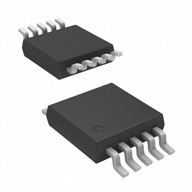
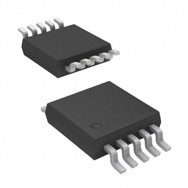
| 描述 | IC REG BOOST 2.8V 0.1A 10MSOP稳压器—开关式稳压器 2.8V 100mA Boost |
| 产品分类 | |
| 品牌 | Texas Instruments |
| 产品手册 | |
| 产品图片 |
|
| rohs | 符合RoHS无铅 / 符合限制有害物质指令(RoHS)规范要求 |
| 产品系列 | 电源管理 IC,稳压器—开关式稳压器,Texas Instruments TPS61004DGS- |
| 数据手册 | |
| 产品型号 | TPS61004DGS |
| PWM类型 | 电流模式 |
| 产品种类 | 稳压器—开关式稳压器 |
| 供应商器件封装 | 10-VSSOP |
| 其它名称 | 296-3221-5 |
| 包装 | 管件 |
| 单位重量 | 23.700 mg |
| 同步整流器 | 无 |
| 商标 | Texas Instruments |
| 安装类型 | 表面贴装 |
| 安装风格 | SMD/SMT |
| 宽度 | 3 mm |
| 封装 | Tube |
| 封装/外壳 | 10-TFSOP,10-MSOP(0.118",3.00mm 宽) |
| 封装/箱体 | VSSOP-10 |
| 工作温度 | -40°C ~ 85°C |
| 工作温度范围 | - 40 C to + 85 C |
| 工厂包装数量 | 80 |
| 开关频率 | 360 kHz to 840 kHz |
| 拓扑结构 | Boost |
| 最大工作温度 | + 85 C |
| 最大输入电压 | 2.8 V |
| 最小工作温度 | - 40 C |
| 最小输入电压 | 800 mV |
| 标准包装 | 80 |
| 电压-输入 | 0.8 V ~ 2.8 V |
| 电压-输出 | 2.8V |
| 电流-输出 | 100mA |
| 类型 | 升压(升压) |
| 系列 | TPS61004 |
| 负载调节 | 0.25 % |
| 输出数 | 1 |
| 输出电压 | 2.8 V |
| 输出电流 | 100 mA/250 mA |
| 输出端数量 | 1 Output |
| 输出类型 | 固定 |
| 频率-开关 | 500kHz |


- 商务部:美国ITC正式对集成电路等产品启动337调查
- 曝三星4nm工艺存在良率问题 高通将骁龙8 Gen1或转产台积电
- 太阳诱电将投资9.5亿元在常州建新厂生产MLCC 预计2023年完工
- 英特尔发布欧洲新工厂建设计划 深化IDM 2.0 战略
- 台积电先进制程称霸业界 有大客户加持明年业绩稳了
- 达到5530亿美元!SIA预计今年全球半导体销售额将创下新高
- 英特尔拟将自动驾驶子公司Mobileye上市 估值或超500亿美元
- 三星加码芯片和SET,合并消费电子和移动部门,撤换高东真等 CEO
- 三星电子宣布重大人事变动 还合并消费电子和移动部门
- 海关总署:前11个月进口集成电路产品价值2.52万亿元 增长14.8%


PDF Datasheet 数据手册内容提取
Product Sample & Technical Tools & Support & Folder Buy Documents Software Community TPS61000,TPS61001,TPS61002,TPS61003 TPS61004,TPS61005,TPS61006,TPS61007 SLVS279D–MARCH2000–REVISEDAUGUST2015 TPS6100x Single- and Dual-Cell Boost Converter With Start-up Into Full Load 1 Features 3 Description • Start-UpIntoaFullLoadWithSupplyVoltagesas TheTPS6100xdevicesareboostconvertersintended 1 for systems that are typically operated from a single- Lowas0.9VOverFullTemperatureRange or dual-cell nickel-cadmium (NiCd), nickel-metal • Minimum100-mAOutputCurrentFrom0.8-V hydride (NiMH), or alkaline battery. The converter SupplyVoltage,250mAFrom1.8V output voltage can be adjusted from 1.5 V to a • HighPowerConversionEfficiency,upto90% maximum of 3.3 V and provides a minimum output current of 100 mA from a single battery cell and 250 • Power-SaveModeforImprovedEfficiencyatLow mA from two battery cells. The converter starts up OutputCurrents into a full load with a supply voltage of 0.9 V and • DeviceQuiescentCurrentLessThan50µA stays in operation with supply voltages as low as 0.8 • AddedSystemSecurityWithIntegratedLow- V. BatteryComparator The converter is based on a fixed-frequency, current- • Low-EMIConverter(IntegratedAntiringingSwitch mode pulse-width-modulation (PWM) controller that AcrossInductor) goes into power-save mode at low load currents. The • Micro-Size10-PinMSOPPackage current through the switch is limited to a maximum of 1100 mA, depending on the output voltage. The • EvaluationModulesAvailable current sense is integrated to further minimize (TPS6100xEVM–156) external component count. The converter can be disabled to minimize battery drain when the system is 2 Applications putintostandby. • Single-andDual-CellBatteryOperatedProducts A low-EMI mode is implemented to reduce • MP3-PlayersandWirelessHeadsets interference and radiated electromagnetic energy that is caused by the ringing of the inductor when the • PagersandCordlessPhones inductor discharge-current decreases to zero. The • PortableMedicalDiagnosticEquipment device is packaged in the space-saving 10-pin MSOP • RemoteControls package. DeviceInformation(1) PARTNUMBER PACKAGE BODYSIZE(NOM) TPS6100x VSSOP(10) 3.00mm×3.00mm (1) For all available packages, see the orderable addendum at theendofthedatasheet. TypicalApplicationCircuitforFixedOutput TPS61006Start-UpTimingInto33-ΩLoad VoltageOptions 140 L1 D1 VO=3.3V 3 VOUT 120 33 µH Ci 7 V A 10µF6 VBAT SW VOUT 5 R3 22CµoF Voltage- 2 IOUT 81000rrent-m R1 9 LBI LBO 10 ut 60 Cu LowBattery utp put R2 TPS61006 Warning O 1 40 ut - O 8 NC FB 3 VO - 20 IO R4 EN ON 10kΩ 1 EN COMP 2 0 0 OFF GND 4 C1 C2 0 2 4 6 8 10 12 14 16 18 20 100pF 33nF Time- ms 1 An IMPORTANT NOTICE at the end of this data sheet addresses availability, warranty, changes, use in safety-critical applications, intellectualpropertymattersandotherimportantdisclaimers.PRODUCTIONDATA.
TPS61000,TPS61001,TPS61002,TPS61003 TPS61004,TPS61005,TPS61006,TPS61007 SLVS279D–MARCH2000–REVISEDAUGUST2015 www.ti.com Table of Contents 1 Features.................................................................. 1 9.4 DeviceFunctionalModes........................................13 2 Applications........................................................... 1 10 ApplicationandImplementation........................ 14 3 Description............................................................. 1 10.1 ApplicationInformation..........................................14 4 RevisionHistory..................................................... 2 10.2 TypicalApplication ...............................................15 5 AvailableOptions................................................... 3 11 PowerSupplyRecommendations..................... 20 6 PinConfigurationandFunctions......................... 3 12 Layout................................................................... 20 12.1 LayoutGuidelines.................................................20 7 Specifications......................................................... 4 12.2 LayoutExample....................................................20 7.1 AbsoluteMaximumRatings......................................4 12.3 ThermalConsiderations........................................21 7.2 ESDRatings..............................................................4 13 DeviceandDocumentationSupport................. 22 7.3 RecommendedOperatingConditions.......................4 7.4 ThermalInformation..................................................4 13.1 DeviceSupport......................................................22 7.5 ElectricalCharacteristics...........................................5 13.2 RelatedLinks........................................................22 7.6 TypicalCharacteristics..............................................7 13.3 CommunityResources..........................................22 13.4 Trademarks...........................................................22 8 ParameterMeasurementInformation..................9 13.5 ElectrostaticDischargeCaution............................22 9 DetailedDescription............................................ 10 13.6 Glossary................................................................22 9.1 Overview.................................................................10 14 Mechanical,Packaging,andOrderable 9.2 FunctionalBlockDiagrams.....................................10 Information........................................................... 23 9.3 FeatureDescription.................................................12 4 Revision History NOTE:Pagenumbersforpreviousrevisionsmaydifferfrompagenumbersinthecurrentversion. ChangesfromRevisionC(April2003)toRevisionD Page • AddedPinConfigurationandFunctionssection,ESDRatingstable,FeatureDescriptionsection,DeviceFunctional Modes,ApplicationandImplementationsection,PowerSupplyRecommendationssection,Layoutsection,Device andDocumentationSupportsection,andMechanical,Packaging,andOrderableInformationsection .............................. 1 • ReplacedtheDissipationRatingstablewiththeThermalInformationtable.......................................................................... 4 2 SubmitDocumentationFeedback Copyright©2000–2015,TexasInstrumentsIncorporated ProductFolderLinks:TPS61000 TPS61001 TPS61002 TPS61003TPS61004 TPS61005 TPS61006 TPS61007
TPS61000,TPS61001,TPS61002,TPS61003 TPS61004,TPS61005,TPS61006,TPS61007 www.ti.com SLVS279D–MARCH2000–REVISEDAUGUST2015 5 Available Options T PACKAGE OUTPUTVOLTAGE PARTNUMBER(1) MARKINGDGS A (V) PACKAGE Adj.from1.5Vto3.3V TPS61000DGS ADA 1.5 TPS61001DGS ADB 1.8 TPS61002DGS ADC 2.5 TPS61003DGS ADD –40°Cto85°C 10-PinMSOPDGS 2.8 TPS61004DGS ADE 3.0 TPS61005DGS ADF 3.3 TPS61006DGS ADG Adj.from1.5Vto3.3V TPS61007DGS AD (1) TheDGSpackageisavailabletapedandreeled.AddRsuffixtodevicetype(e.g.TPS61000DGSR)toorderquantitiesof2500devices perreel. 6 Pin Configuration and Functions DGSPackage 10-PinVSSOP TopView EN 1 10 LBO COMP 2 9 LBI FB 3 8 NC/FBGND GND 4 7 SW VOUT 5 6 VBAT TPS61007 only PinFunctions PIN I/O DESCRIPTION NAME NO. Compensationoferroramplifier.ConnectR-C-Cnetworktosetfrequencyresponseofcontrolloop.Seethe COMP 2 — Applicationsectionformoredetails. Chip-enableinput.TheconverterisswitchedonifENissethigh,andisswitchedoffwhenENisconnectedto EN 1 I ground(shutdownmode). Feedbackinputforadjustableoutputvoltage(TPS61000only).Theoutputvoltageisprogrammeddepending FB 3 I onthevaluesofresistorsR1andR2.Forthefixedoutputvoltageversions(TPS61000,TPS61002, TPS61003,TPS61004,TPS61005,TPS61006),leavetheFBpinunconnected. Notconnected(TPS61000,TPS61002,TPS61003,TPS61004,TPS61005,TPS61006).Agroundpinforthe NC/FBGND 8 — feedbackresistordividerfortheTPS61007only. GND 4 — Ground Low-batterydetectorinput.Alow-batterysignalisgeneratedattheLBOpinwhenthevoltageonLBIdrops LBI 9 I belowthethresholdof500mV.ConnectLBItoGNDorV ifthelow-batterydetectorfunctionisnotused. BAT Donotleavethispinfloating. Open-drainlow-batterydetectoroutput.ThispinispulledlowifthevoltageonLBIdropsbelowthethreshold LBO 10 O of500mV.ApullupresistorshouldbeconnectedbetweenLBOandV . OUT SW 7 I Switchinputpin.Thenodebetweeninductorandanodeoftherectifierdiodeisconnectedtothispin. V 6 I Supplypin BAT V 5 O Outputvoltage.Forthefixedoutputvoltageversions,theintegratedresistivedividerisconnectedtothispin. OUT Copyright©2000–2015,TexasInstrumentsIncorporated SubmitDocumentationFeedback 3 ProductFolderLinks:TPS61000 TPS61001 TPS61002 TPS61003TPS61004 TPS61005 TPS61006 TPS61007
TPS61000,TPS61001,TPS61002,TPS61003 TPS61004,TPS61005,TPS61006,TPS61007 SLVS279D–MARCH2000–REVISEDAUGUST2015 www.ti.com 7 Specifications 7.1 Absolute Maximum Ratings overoperatingfree-airtemperaturerange(unlessotherwisenoted)(1) MIN MAX UNIT Inputvoltage(V ,V ,COMP,FB,LBO,EN,LBI) –0.3 3.6 V BAT OUT V I Inputvoltage(SW) –0.3 V +0.7 V OUT PeakcurrentintoSW 1300 mA Continuoustotalpowerdissipation SeeThermalInformation T Operatingfree-airtemperature –40 85 °C A T Maximumjunctiontemperature 150 °C J Leadtemperature 260 °C T Storagetemperature –65 150 °C stg (1) StressesbeyondthoselistedunderAbsoluteMaximumRatingsmaycausepermanentdamagetothedevice.Thesearestressratings only,whichdonotimplyfunctionaloperationofthedeviceattheseoranyotherconditionsbeyondthoseindicatedunderRecommended OperatingConditions.Exposuretoabsolute-maximum-ratedconditionsforextendedperiodsmayaffectdevicereliability. 7.2 ESD Ratings VALUE UNIT Humanbodymodel(HBM),perANSI/ESDA/JEDECJS-001(1) ±1000 V(ESD) Electrostaticdischarge Charged-devicemodel(CDM),perJEDECspecificationJESD22- ±500 V C101(2) (1) JEDECdocumentJEP155statesthat500-VHBMallowssafemanufacturingwithastandardESDcontrolprocess. (2) JEDECdocumentJEP157statesthat250-VCDMallowssafemanufacturingwithastandardESDcontrolprocess. 7.3 Recommended Operating Conditions overoperatingfree-airtemperaturerange(unlessotherwisenoted) MIN NOM MAX UNIT V Supplyvoltage 0.8 V V BAT O V =0.8V 100 BAT V Outputcurrent mA O V =0.8V 250 BAT Inductor 10 33 µH Inputcapacitor 10 µF Outputcapacitor 22 µF T Operatingjunctiontemperature –40 125 °C J 7.4 Thermal Information TPS6100x THERMALMETRIC(1) DGS(VSSOP) UNIT 10PINS R Junction-to-ambientthermalresistance 160.6 °C/W θJA R Junction-to-case(top)thermalresistance 54.4 °C/W θJC(top) R Junction-to-boardthermalresistance 80.5 °C/W θJB ψ Junction-to-topcharacterizationparameter 6.3 °C/W JT ψ Junction-to-boardcharacterizationparameter 79.2 °C/W JB R Junction-to-case(bottom)thermalresistance N/A °C/W θJC(bot) (1) Formoreinformationabouttraditionalandnewthermalmetrics,seetheSemiconductorandICPackageThermalMetricsapplication report,SPRA953. 4 SubmitDocumentationFeedback Copyright©2000–2015,TexasInstrumentsIncorporated ProductFolderLinks:TPS61000 TPS61001 TPS61002 TPS61003TPS61004 TPS61005 TPS61006 TPS61007
TPS61000,TPS61001,TPS61002,TPS61003 TPS61004,TPS61005,TPS61006,TPS61007 www.ti.com SLVS279D–MARCH2000–REVISEDAUGUST2015 7.5 Electrical Characteristics overrecommendedoperatingfree-airtemperaturerange,V =1.2V,EN=V (unlessotherwisenoted) BAT BAT PARAMETER TESTCONDITIONS MIN TYP MAX UNIT R =33Ω 0.9 L Inputvoltageforstartup V R =3kΩ, T =25°C 0.8 V I L A Inputvoltageoncestarted I =100mA 0.8 O Programmableoutputvoltage TPS61000, V I =100mA 1.5 3.3 V O TPS61007 O 1.2V, I =1mA 1.44 1.5 1.55 O TPS61001 V 0.8V<V <V , I =100mA 1.45 1.5 1.55 I O O 1.2V, I =1mA 1,72 1.8 1.86 O TPS61002 V 0.8V<V <V , I =100mA 1.74 1.8 1.86 I O O 1.2V, I =1mA 2.40 2.5 2.58 O TPS61003 0.8V<V <V , I =100mA 2.42 2.5 2.58 V I O O 1.6V<V <V , I =200mA 2.42 2.5 2.58 I O O 1.2V, I =1mA 2.68 2.8 2.89 O V Outputvoltage O TPS61004 0.8V<V <V , I =100mA 2.72 2.8 2.89 V I O O 1.6V<V <V , I =200mA 2.72 2.8 2.89 I O O 1.2V, I =1mA 2.88 3.0 3.1 O TPS61005 0.8V<V <V , I =100mA 2.9 3.0 3.1 V I O O 1.6V<V <V , I =200mA 2.9 3.0 3.1 I O O 1.2V, I =1mA 3.16 3.3 3.4 O TPS61006 0.8V<V <V , I =100mA 3.2 3.3 3.4 V I O O 1.6V<V <V , I =200mA 3.2 3.3 3.4 I O O V =0.8V 100 mA I I Maximumcontinuousoutputcurrent O V =1.8V 250 I TPS61001 0.5 TPS61002 0.65 TPS61003 0.9 I Switchcurrentlimit 0.8V<V <V A ILIM I O TPS61004 0.95 TPS61005 1 TPS61006 1.1 TPS61000, V Feedbackvoltage 468 500 515 mV FB TPS61007 f Oscillatorfrequency 360 500 840 kHz D Maximumdutycycle 85% MAX r Switch-onresistance V =3.3V 0.18 0.27 Ω DS(on) O Lineregulation (1) V =0.8Vto1.25V, I =50mA 0.3 %/V I O Loadregulationfixedoutputvoltage V =1.2V, I =10mAto90mA 0.25% I O versions (1) I =0mA, V 44 Quiescentcurrentdrawnfrompowersource O BAT I V =V, µA Q ower(currentintoVBATandintoVOUT) VEON=3.4IV VOUT 6 I Shutdowncurrentfrompowersource SD V =0V 0.2 5 µA (currentintoV andintoV ) EN BAT OUT 0.2x V ENlow-levelinputvoltage V IL V BAT 0.8× V ENhigh-levelinputvoltage V IH V BAT (1) Lineandloadregulationismeasuredasapercentagedeviationfromthenominalvalue(i.e.,aspercentagedeviationfromthenominal outputvoltage).Forlineregulation,x%/Vstandsfor±x%changeofthenominaloutputvoltageper1-Vchangeontheinput/supply voltage.Forloadregulation,y%standsfor±y%changeofthenominaloutputvoltageperthespecifiedcurrentchange. Copyright©2000–2015,TexasInstrumentsIncorporated SubmitDocumentationFeedback 5 ProductFolderLinks:TPS61000 TPS61001 TPS61002 TPS61003TPS61004 TPS61005 TPS61006 TPS61007
TPS61000,TPS61001,TPS61002,TPS61003 TPS61004,TPS61005,TPS61006,TPS61007 SLVS279D–MARCH2000–REVISEDAUGUST2015 www.ti.com Electrical Characteristics (continued) overrecommendedoperatingfree-airtemperaturerange,V =1.2V,EN=V (unlessotherwisenoted) BAT BAT PARAMETER TESTCONDITIONS MIN TYP MAX UNIT ENinputcurrent EN=GNDorV 0.1 1 µA BAT V LBIlow-levelinputvoltagethreshold V voltagedecreasing 470 500 530 IL LBI mV LBIinputhysteresis 10 I LBIinputcurrent 0.01 0.1 µA I V LBOlow-leveloutputvoltage V =0V,V =3.3V,I =50µA 0.04 0.2 V OL LBI O OL LBOoutputleakagecurrent V =650mV,V =3.3V 0.01 1 µA LBI LBO I FBinputbiascurrent(TPS61000, V =500mV 0.01 0.1 FB FB µA TPS61007only) 6 SubmitDocumentationFeedback Copyright©2000–2015,TexasInstrumentsIncorporated ProductFolderLinks:TPS61000 TPS61001 TPS61002 TPS61003TPS61004 TPS61005 TPS61006 TPS61007
TPS61000,TPS61001,TPS61002,TPS61003 TPS61004,TPS61005,TPS61006,TPS61007 www.ti.com SLVS279D–MARCH2000–REVISEDAUGUST2015 7.6 Typical Characteristics Table1.TableofGraphs TITLE vsOutputCurrent Figure1,Figure2 η Efficiency vsInductorType Figure3 vsInputVoltage Figure4 I MaximumOutputCurrent vsInputVoltage Figure5 O V OutputVoltage vsOutputCurrent Figure6 O V TPS61007OutputVoltage vsOutputCurrent Figure7 O I No-LoadSupplyCurrent vsInputVoltage Figure8 Q I ShutdownCurrent vsInputVoltage Figure9 SD V MinimumStart-UpInputVoltage vsLoadCurrent Figure10 I I SwitchCurrentLimit vsOutputVoltage Figure11 LIM 100 100 VI= 1.2 V VI= 2.4 V 90 90 VO= 3.3 V 80 80 −% 7600 VO= 3.3 V VO= 1.5 V −% 6700 VO= 2.8 V ncy 50 ncy 50 Efficie 40 Efficie 40 30 30 20 20 10 10 0 0 1 10 100 1000 1 10 100 1000 IO−Output Current−mA IO−Output Current−mA Figure1.EfficiencyvsOutputCurrency Figure2.EfficiencyvsOutputCurrency 100 95 95 VVIO== 1 3.2.3 V V IO= 50 mA IO= 100 mA 90 90 85 85 % 80 % IO= 100 mA Efficiency− 7705 Efficiency− 7850 65 70 60 55 65 50 Coilcraft Coilcraft Coiltronics Coiltronics Sumida Sumida 60 DO1608C DS1608C UP1B UP2B CD43 CD54 0.80 1.30 1.80 2.30 2.80 3.30 Inductor Type VI−Input Voltage−V Figure3.EfficiencyvsInductorType Figure4.EfficiencyvsInputVoltage Copyright©2000–2015,TexasInstrumentsIncorporated SubmitDocumentationFeedback 7 ProductFolderLinks:TPS61000 TPS61001 TPS61002 TPS61003TPS61004 TPS61005 TPS61006 TPS61007
TPS61000,TPS61001,TPS61002,TPS61003 TPS61004,TPS61005,TPS61006,TPS61007 SLVS279D–MARCH2000–REVISEDAUGUST2015 www.ti.com 1 3.60 VI= 1.2 V 0.90 VO= 3.2 V 3.40 3.3 V 0.80 3.20 A − Current 00..6700 VO= 1.75 VVO= 2.42 V ge−V 2.830 −Maximum Output 0000....23450000 VO= 1.45 V −oltVOutput VaO 222...0462000 2.5 V O 1.8 V I 0.10 1.80 1.60 0 1 10 100 1000 0.8 1 1.2 1.4 1.6 1.8 2 2.2 2.4 2.6 2.8 3 VI−Input Voltage−V IO−Output Current−mA Figure5.MaximumOutputCurrentvsInputVoltage Figure6.TPS61002/3/6OutputVoltagevsOutputCurrent 3.60 45 3.40 VI= 1.2 V VO= 3.3 V 40 TA= 85°C V 3.20 −Am 35 TA= 25°C utput Voltage− 22..68300 VO= 2.5 V Supply Current 223050 TA=−40°C O 2.40 d −VO 2.20 o-Loa 15 2 VO= 1.8 V −NQ 10 I 1.80 5 1.60 0 0.1 1 10 100 1000 0.80 1.30 1.80 2.30 2.80 3.30 3.80 IO−Output Current−mA VI−Input Voltage−V Figure7.TPS61007OutputVoltagevsOutputCurrent Figure8.No-LoadSupplyCurrentvsInputVoltage 1800 0.90 1600 TA= 85°C V VO= min 3.2 V e− 0.85 1400 ag nA 1200 oltut V 0.80 − p ent 1000 p In own Curr 800 m Start-U 0.75 utd 600 mu 0.70 −Sh 400 Mini ISD 200 TA= 25°C −VI 0.65 TA=−40°C 0 0.60 0.80 1.30 1.80 2.30 2.80 3.30 3.80 0 10 20 30 40 50 60 70 80 90 100 VI−Input Voltage−V IO−Load Current−mA Figure9.ShutdownCurrentvsInputVoltage Figure10.MinimumStart-upInputVoltagevsLoadCurrent 8 SubmitDocumentationFeedback Copyright©2000–2015,TexasInstrumentsIncorporated ProductFolderLinks:TPS61000 TPS61001 TPS61002 TPS61003TPS61004 TPS61005 TPS61006 TPS61007
TPS61000,TPS61001,TPS61002,TPS61003 TPS61004,TPS61005,TPS61006,TPS61007 www.ti.com SLVS279D–MARCH2000–REVISEDAUGUST2015 1.5 VI= 1.2 V A − mit 1 Li nt e urr C h c wit 0.5 S − M LI I 0 1.5 1.7 1.9 2.1 2.3 2.5 2.7 2.9 3.1 3.3 3.5 VO−Output Voltage−V Figure11.TPS61000,TPS61007SwitchCurrentLimitvsOutputVoltage 8 Parameter Measurement Information L1 D1 List of Components: 33µH Ci 7 IC1: Only fixed output versions 10µF SW Co (unless otherwise noted) 6 VBAT VOUT 5 22µF L1: Coilcraft DO3308P−333 D1: Motorola Schottky Diode R3 MBRM120LT3 R1 9 LBI LBO 10 Low Battery CI: Ceramic Warning CO: Ceramic R2 TPS6100x 8 NC/FBGND FB 3 R4 ON 10 kΩ 1 EN COMP 2 OFF GND C1 C2 4 100 pF 33 nF Figure12. CircuitUsedforTypicalCharacteristicsMeasurements Copyright©2000–2015,TexasInstrumentsIncorporated SubmitDocumentationFeedback 9 ProductFolderLinks:TPS61000 TPS61001 TPS61002 TPS61003TPS61004 TPS61005 TPS61006 TPS61007
TPS61000,TPS61001,TPS61002,TPS61003 TPS61004,TPS61005,TPS61006,TPS61007 SLVS279D–MARCH2000–REVISEDAUGUST2015 www.ti.com 9 Detailed Description 9.1 Overview The TPS6100x Non-synchronous step-up converter typically operates at a 500-kHz frequency pulse width modulation (PWM) at moderate to heavy load currents. The converter enters Power Save mode at low load currentstomaintainahighefficiencyoverawideload.Additionally,thedeviceintegratesacircuitwhichremoves theringingthattypicallyappearsontheSW-nodewhentheconverterentersthediscontinuouscurrentmode. 9.2 Functional Block Diagrams L1 D1 CI SW VOUT CO Antiringing Comparator VBAT and Switch UVLO Control Logic Current Sense EN Oscillator Current Limit LBI/LBO Gate Drive Slope Compensation Comparator LBI VREF Comparator Bandgap Error Reference LBO Amplifier GND COMP Figure13. FixedOutput-VoltageOption 10 SubmitDocumentationFeedback Copyright©2000–2015,TexasInstrumentsIncorporated ProductFolderLinks:TPS61000 TPS61001 TPS61002 TPS61003TPS61004 TPS61005 TPS61006 TPS61007
TPS61000,TPS61001,TPS61002,TPS61003 TPS61004,TPS61005,TPS61006,TPS61007 www.ti.com SLVS279D–MARCH2000–REVISEDAUGUST2015 Functional Block Diagrams (continued) L1 D1 CI SW CO Antiringing Comparator VBAT and Switch VOUT UVLO Control Logic Current Sense EN Oscillator Current Limit LBI/LBO Gate Drive Slope Compensation Comparator LBI FB VREF Comparator Bandgap Error Reference LBO Amplifier GND COMP Figure14. AdjustableOutput-VoltageOption(TPS61000Only) L1 D1 CI SW CO Antiringing Comparator VBAT and Switch VOUT UVLO Control Logic Current Sense EN Oscillator Current Limit LBI/LBO Gate Drive Slope Compensation Comparator LBI FB VREF Comparator Bandgap Error Reference LBO Amplifier FBGND GND COMP Figure15. AdjustableOutput-VoltageOption(TPS61007Only) Copyright©2000–2015,TexasInstrumentsIncorporated SubmitDocumentationFeedback 11 ProductFolderLinks:TPS61000 TPS61001 TPS61002 TPS61003TPS61004 TPS61005 TPS61006 TPS61007
TPS61000,TPS61001,TPS61002,TPS61003 TPS61004,TPS61005,TPS61006,TPS61007 SLVS279D–MARCH2000–REVISEDAUGUST2015 www.ti.com 9.3 Feature Description 9.3.1 ControllerCircuit The device is based on a current-mode control topology using a constant-frequency pulse-width modulator to regulate the output voltage. It runs at an oscillator frequency of 500 kHz. The current sense is implemented by measuring the voltage across the switch. The controller also limits the current through the power switch on a pulse-by-pulse basis. Care must be taken that the inductor saturation current is higher than the current limit of the TPS6100x. This prevents the inductor from going into saturation and therefore protects both device and inductor.Thecurrentlimitshouldnotbecomeactiveduringnormaloperatingconditions. The TPS6100x is designed for high efficiency over a wide output current range. Even at light loads the efficiency stayshighbecausethecontrollerentersapower-savemode,minimizingswitchinglossesoftheconverter.Inthis mode, the controller only switches if the output voltage trips below a set threshold voltage. It ramps up the output voltage with one or several pulses, and again goes into the power-save mode once the output voltage exceeds the threshold voltage. The controller enters the power-save mode when the output current drops to levels that force the discontinuous current mode. It calculates a minimum duty cycle based on input and output voltage and usesthecalculationforthetransitionoutofthepower-savemodeintocontinuouscurrentmode. The control loop must be externally compensated with an R/C/C network connected to the COMP pin. See the applicationsectionformoredetailsonthedesignofthecompensationnetwork. 9.3.2 DeviceEnable The device is put into operation when EN is set high. During start-up of the converter the input current from the battery is limited until the voltage on COMP reaches its operating point. The device is put into a shutdown mode when EN is set to GND. In this mode, the regulator stops switching and all internal control circuitry including the low-battery comparator is switched off. The output voltage drops to one diode drop below the input voltage in shutdown. 9.3.3 UndervoltageLockout An undervoltage lockout function prevents the device start-up if the supply voltage on V is lower than BAT approximately 0.7 V. This undervoltage lockout function is implemented in order to prevent the malfunctioning of the converter. When in operation and the battery is being discharged, the device automatically enters the shutdownmodeifthevoltageonV dropsbelowapproximately0.7V. BAT If the EN pin is hardwired to V and if the voltage at V drops temporarily below the UVLO threshold voltage, BAT BAT the device switches off and does not start up again automatically, even if the supply voltage rises above 0.9 V. The device starts up again only after a signal change from low to high on EN or if the battery voltage is completelyremoved. 9.3.4 Low-BatteryDetectorCircuit(LBIandLBO) The low-battery detector circuit is typically used to supervise the battery voltage and to generate an error flag when the battery voltage drops below a user-set threshold voltage. The function is active only when the device is enabled. When the device is disabled, the LBO pin is high impedance. The LBO pin goes active low when the voltage on the LBI pin decreases below the set threshold voltage of 500 mV ±15 mV, which is equal to the internalreferencevoltage.Thebatteryvoltage,atwhichthedetectioncircuitswitches,canbeprogrammedwitha resistive divider connected to the LBI pin. The resistive divider scales down the battery voltage to a voltage level of 500 mV, which is then compared to the LBI threshold voltage. The LBI pin has a built-in hysteresis of 10 mV. SeetheapplicationsectionformoredetailsabouttheprogrammingoftheLBIthreshold. If the low-battery detection circuit is not used, the LBI pin should be connected to GND (or to V ) and the LBO BAT pincanbeleftunconnected.DonotlettheLBIpinfloat. 9.3.5 Low-EMISwitch The device integrates a circuit which removes the ringing that typically appears on the SW-node when the converterentersthediscontinuouscurrentmode.Inthiscase,thecurrentthroughtheinductorrampstozeroand the Schottky diode stops conducting. Due to remaining energy that is stored in parasitic components of the diode, inductor, and switch, a ringing on the SW pin is induced. The integrated antiringing switch clamps this voltageinternallytoV andthereforedampensthisringing. BAT 12 SubmitDocumentationFeedback Copyright©2000–2015,TexasInstrumentsIncorporated ProductFolderLinks:TPS61000 TPS61001 TPS61002 TPS61003TPS61004 TPS61005 TPS61006 TPS61007
TPS61000,TPS61001,TPS61002,TPS61003 TPS61004,TPS61005,TPS61006,TPS61007 www.ti.com SLVS279D–MARCH2000–REVISEDAUGUST2015 Feature Description (continued) The antiringing switch is turned on by a comparator that monitors the voltage between SW and V . This OUT voltage indicates when the diode is reverse biased. The ringing on the SW-node is damped to a large degree, reducingtheelectromagneticinterferencegeneratedbytheswitchingregulatortoagreatextent. 9.3.6 AdjustableOutputVoltage(TPS61000andTPS61007Only) The accuracy of the internal voltage reference, the controller topology, and the accuracy of the external resistor divider determine the accuracy of the adjustable output voltage versions. The reference voltage has an accuracy of ±4% over line, load, and temperature. The controller switches between fixed frequency and pulse-skip mode, depending on load current. This adds an offset to the output voltage that is equivalent to 1% of V . Using 1% O accurate resistors for the feedback divider, a total accuracy of ±6% can be achieved over the complete temperature and output current range. The TPS61007 is an improved adjustable output voltage version. Ground shift in the feedback loop was eliminated by adding a separate ground pin for the feedback resistor divider (FBGND). 9.4 Device Functional Modes 9.4.1 PowerSaveMode The TPS6100x enters a power-save mode, minimizing switching losses of the converter. In this mode, the controller only switches if the output voltage trips below a set threshold voltage. It ramps up the output voltage with one or several pulses, and again goes into the power-save mode once the output voltage exceeds the thresholdvoltage. Copyright©2000–2015,TexasInstrumentsIncorporated SubmitDocumentationFeedback 13 ProductFolderLinks:TPS61000 TPS61001 TPS61002 TPS61003TPS61004 TPS61005 TPS61006 TPS61007
TPS61000,TPS61001,TPS61002,TPS61003 TPS61004,TPS61005,TPS61006,TPS61007 SLVS279D–MARCH2000–REVISEDAUGUST2015 www.ti.com 10 Application and Implementation NOTE Information in the following applications sections is not part of the TI component specification, and TI does not warrant its accuracy or completeness. TI’s customers are responsible for determining suitability of components for their purposes. Customers should validateandtesttheirdesignimplementationtoconfirmsystemfunctionality. 10.1 Application Information The TPS6100x boost converter family is intended for systems that are powered by a single-cell NiCd or NiMH batterywithatypicalterminalvoltagebetween0.9Vto1.6V.Itcanalsobeusedinsystemsthatarepoweredby two-cell NiCd or NiMH batteries with a typical stack voltage between 1.8 V and 3.2 V. Additionally, singleor dual- cell, primary and secondary alkaline battery cells can be the power source in systems where the TPS6100x is used. 10.1.1 SchematicofTPS6100xEvaluationModules(TPS6100XEVM156) J1 LP1 R6 C5 R5 TPS6100x EN LBO C6 COMP LBI FB NC/FBGND OUT R3 L1 R2 R1 IN R4 GND SW V V OUT BAT C2 C1 C3 D1 Figure16. SchematicofTPS6100xEvaluationModules EvaluationmodulesareavailablefordevicetypesTPS61000,TPS61002,TPS61003,andTPS61006. 14 SubmitDocumentationFeedback Copyright©2000–2015,TexasInstrumentsIncorporated ProductFolderLinks:TPS61000 TPS61001 TPS61002 TPS61003TPS61004 TPS61005 TPS61006 TPS61007
TPS61000,TPS61001,TPS61002,TPS61003 TPS61004,TPS61005,TPS61006,TPS61007 www.ti.com SLVS279D–MARCH2000–REVISEDAUGUST2015 10.2 Typical Application D1 L1 VO 33µH Ci 7 CO 10µF SW 5 22µF 10 V VOUT 10 V R5 R3 6 10 Low Battery VBAT LBO Warning R1 9 3 LBI FB TPS61007 R4 R2 8 FBGND 1 EN Alkaline Cell RC 10 kΩ 2 COMP GND 4 CC1 CC2 100 pF 33 nF Figure17. TypicalApplicationCircuitforAdjustableOutputVoltageOption 10.2.1 DesignRequirements SeeTable2fordesignparameters. Table2.TPS6100xOutputDesignParameters DESIGNPARAMETERS VALUES Inputvoltagerange 1.8Vto3.3V Outputvoltage 3.3V Outputvoltageripple ±3%VOUT 10.2.2 DetailedDesignProcedure 10.2.2.1 ProgrammingtheTPS61000andTPS61007AdjustableOutputVoltageDevices The output voltage of the TPS61000 and TPS61007 can be adjusted with an external resistor divider. The typical value of the voltage on the FB pin is 500 mV in fixed-frequency operation and 485 mV in the power-save operation mode. The maximum allowed value for the output voltage is 3.3 V. The current through the resistive divider should be about 100 times greater than the current into the FB pin. The typical current into the FB pin is 0.01 µA, and the voltage across R4 is typically 500 mV. Based on those two values, the recommended value for R4 is in the range of 500 kΩ in order to set the divider current at 1 µA. From that, the value of resistor R3, dependingontheneededoutputvoltageV ,canbecalculatedusingthefollowingequation: OUT § V · § V · 5(cid:22) 5(cid:23)u¨ O ±(cid:20)¸ (cid:24)(cid:19)(cid:19)N:u¨ O ±(cid:20)¸ ©VFB ¹ ©500mV ¹ (1) If,asanexample,anoutputvoltageof2.5Visneeded,a2-MΩresistorshouldbechosenforR3. The TPS61007 is an improved version of the TPS61000 adjustable output voltage device. The FBGND pin is internallyconnectedtoGND. Copyright©2000–2015,TexasInstrumentsIncorporated SubmitDocumentationFeedback 15 ProductFolderLinks:TPS61000 TPS61001 TPS61002 TPS61003TPS61004 TPS61005 TPS61006 TPS61007
TPS61000,TPS61001,TPS61002,TPS61003 TPS61004,TPS61005,TPS61006,TPS61007 SLVS279D–MARCH2000–REVISEDAUGUST2015 www.ti.com 10.2.2.2 ProgrammingtheLowBatteryComparatorThresholdVoltage The current through the resistive divider should be about 100 times greater than the current into the LBI pin. The typical current into the LBI pin is 0.01 µA. The voltage across R2 is equal to the reference voltage that is generated on-chip, which has a value of 500 mV ±15 mV. The recommended value for R2 is therefore in the range of 500 kΩ. From that, the value of resistor R1, depending on the desired minimum battery voltage (V , BAT) canbecalculatedusingthefollowingequation: §V · § V · 5(cid:20) 5(cid:21)u¨ TRIP ±(cid:20)¸ (cid:24)(cid:19)(cid:19)N:u¨ BAT ±(cid:20)¸ © V ¹ ©0.5 V ¹ REF (2) For example, if the low-battery detection circuit should flag an error condition on the LBO output pin at a battery voltageof1V,aresistorintherangeof500kΩshouldbechosenforR1. The output of the low battery comparator is a simple open-drain output that goes active low if the battery voltage drops below the programmed threshold voltage on LBI. The output requires a pullup resistor with a recommended value of 1MΩ, and should only be pulled up to the V . If not used, the LBO pin can be left OUT floating. 10.2.2.3 InductorSelection The output filter of inductive switching regulators is a low pass filter of second order. It consists of an inductor andacapacitor,oftenreferredtoasstorageinductorandoutputcapacitor. To select an inductor, keep the possible peak inductor current below the current limit threshold of the power switch in your chosen configuration. For example, the current limit threshold of the TPS61006’s switch is 1100 mA at an output voltage of 3.3 V. The highest peak current through the inductor and the switch depends on the output load, the input (V ), and the output voltage (V ). Estimation of the maximum average inductor current BAT OUT canbedoneusingthefollowingequation: V I I u OUT L OUT V u0.8 BAT (3) For example, for an output current of 100 mA at 3.3 V, at least 515-mA current flows through the inductor at a minimuminputvoltageof0.8V. The second parameter for choosing the inductor is the desired current ripple in the inductor. Normally it is advisable to work with a ripple of less than 20% of the average inductor current. A smaller ripple reduces the magnetic hysteresis losses in the inductor as well as output voltage ripple and EMI. But in the same way, the regulationtimeatloadchangerises.Inaddition,alargerinductorincreasesthetotalsystemcost. Withthoseparametersitispossibletocalculatethevaluefortheinductor: 9 u(cid:11)9 ± 9 (cid:12) L BAT OUT BAT ', u¦u 9 L OUT where • fistheswitchingfrequency • ΔI istheripplecurrentintheinductor,thatis20%xI (4) L L In this example, the desired inductor has the value of 12 µH. With this calculated value and the calculated currents, it is possible to chose a suitable inductor. Care has to be taken that load transients and losses in the circuitcanleadtohighercurrentsasestimatedinequation3.Also,thelossesintheinductorcausedbymagnetic hysteresislossesandcopperlossesareamajorparameterfortotalcircuitefficiency. The following inductors from different suppliers were tested. All work with the TPS6100x converter within their specifiedparameters: Table3.RecommendedInductors VENDOR PARTNUMBER DO1608PSeries Coilcraft DS1608PSeries DO3308Series 16 SubmitDocumentationFeedback Copyright©2000–2015,TexasInstrumentsIncorporated ProductFolderLinks:TPS61000 TPS61001 TPS61002 TPS61003TPS61004 TPS61005 TPS61006 TPS61007
TPS61000,TPS61001,TPS61002,TPS61003 TPS61004,TPS61005,TPS61006,TPS61007 www.ti.com SLVS279D–MARCH2000–REVISEDAUGUST2015 Table3.RecommendedInductors(continued) VENDOR PARTNUMBER UP1BSeries Coiltronics UP2BSeries Murata LQH3NSeries CD43Series Sumida CD54Series CDR74BSeries TDK NLC453232TSeries 10.2.2.4 CapacitorSelection The major parameter necessary to define the output capacitor is the maximum allowed output voltage ripple of the converter. This ripple is determined by two parameters of the capacitor, the capacitance and the ESR. It is possibletocalculatetheminimumcapacitanceneededforthedefinedripple,supposingthattheESRiszero. , u(cid:11)9 ± 9 (cid:12) C OUT OUT BAT min ¦u'9u 9 OUT where • fistheswitchingfrequency • ΔVisthemaximumallowedripple. (5) With a chosen ripple voltage of 15 mV, a minimum capacitance of 10 µF is needed. The total ripple will be larger due to the ESR of the output capacitor. This additional component of the ripple can be calculated using the followingequation: 'V I uR ESR OUT ESR (6) An additional ripple of 30 mV is the result of using a tantalum capacitor with a low ESR of 300 mΩ. The total ripple is the sum of the ripple caused by the capacitance and the ripple caused by the ESR of the capacitor. In this example, the total ripple is 45 mV. It is possible to improve the design by enlarging the capacitor or using smaller capacitors in parallel to reduce the ESR or by using better capacitors with lower ESR, like ceramics. For example, a 10-µF ceramic capacitor with an ESR of 50 mΩ is used on the evaluation module (EVM). Tradeoffs havetobemadebetweenperformanceandcostsoftheconvertercircuit. A 10-µF input capacitor is recommended to improve transient behavior of the regulator. A ceramic capacitor or a tantalumcapacitorwitha100-nFceramiccapacitorinparallelplacedclosetotheICisrecommended. 10.2.2.5 RectifierSelection The rectifier diode has a major impact on the overall converter efficiency. Standard diodes are not suitable for low-voltage switched mode power supplies. A Schottky diode with low forward voltage and fast reverse recovery shouldbeusedasarectifiertominimizeoveralllossesofthedc-dcconverter.Themaximumcurrentratingofthe diode must be high enough for the application. The maximum diode current is equal to the maximum current in the inductor that was calculated in equation 3. The maximum reverse voltage is the output voltage. The chosen diodeshouldthereforehaveareversevoltageratinghigherthantheoutputvoltage. Table4.RecommendedDiodes VENDOR PARTNUMBER MotorolaSurface MBRM120LT3 Mount MBR0520LT1 1N1517 MotorolaAxialLead RB520S-30 ROHM RB160L–40 Copyright©2000–2015,TexasInstrumentsIncorporated SubmitDocumentationFeedback 17 ProductFolderLinks:TPS61000 TPS61001 TPS61002 TPS61003TPS61004 TPS61005 TPS61006 TPS61007
TPS61000,TPS61001,TPS61002,TPS61003 TPS61004,TPS61005,TPS61006,TPS61007 SLVS279D–MARCH2000–REVISEDAUGUST2015 www.ti.com The typical forward voltage of those diodes is in the range of 0.35 to 0.45 V assuming a peak diode current of 600mA. 10.2.2.6 CompensationoftheControlLoop An R/C/C network must be connected to the COMP pin in order to stabilize the control loop of the converter. Both the pole generated by the inductor L1 and the zero caused by the ESR and capacitance of the output capacitormustbecompensated.ThenetworkshowninFigure18satisfiestheserequirements. RC 10 kΩ COMP CC1 CC2 100 pF 33 nF Figure18. CompensationoftheControlLoop Resistor R and capacitor C depend on the chosen inductance. For a 33-µH inductor, the capacitance of C C C2 C2 should be chosen to 33 nF, or in other words, if the inductor is xx µH, the chosen compensation capacitor should be xx nF, the same number value. The value of the compensation resistor is then chosen based on the requirement to have a time constant of 0.3 ms for the R/C network of R and C ; hence for a 33-nF capacitor, a C C2 10-kΩ resistorshouldbechosenforR . C Capacitor C is depending on the ESR and capacitance value of the output capacitor, and on the value chosen C1 forR .Itsvalueiscalculatedusingfollowingequation: C C uESR C O COUT C1 3uR C (7) For a selected output capacitor of 22 µF with an ESR of 0.2 Ω, and R of 33 kΩ, the value of C is in the range C C1 of100pF. Table5.RecommendedCompensationComponents OUTPUTCAPACITOR INDUCTOR R C C C C1 C2 [µH] CAPACITANCE ESR [kΩ] [pF] [nF] [µF] [Ω] 33 22 0.2 10 100 33 22 22 0.3 15 100 22 10 22 0.4 33 100 10 10 10 0.1 33 100 10 18 SubmitDocumentationFeedback Copyright©2000–2015,TexasInstrumentsIncorporated ProductFolderLinks:TPS61000 TPS61001 TPS61002 TPS61003TPS61004 TPS61005 TPS61006 TPS61007
TPS61000,TPS61001,TPS61002,TPS61003 TPS61004,TPS61005,TPS61006,TPS61007 www.ti.com SLVS279D–MARCH2000–REVISEDAUGUST2015 10.2.3 ApplicationCurves 3.34 3.36 IO= 2 mA −V 3.32 e 3.34 g a −V 3.30 ut Volt 3.32 oltut Vage 33..2286 V−OutpO 3.30 p ut O 3.24 − 2 O V 3.22 W S 3.20 V 0 3.18 0 1 2 3 4 5 Time−ms 0 1 2 3 4 5 Figure19.TPS61006OutputVoltageRippleAmplitude Figure20.TPS61006OutputVoltageRippleAmplitude V−Output Voltage−VO 333...234 VRIC== 1 3.23 VkΩ V−Outpoltageut V−VO3333....23455555 IROC== 5 303 m kAΩ A m V Output Current− 264000 550 m mAA −Input Voltage− 10..281 −O 0 VI I 0 1 2 3 4 5 6 7 8 9 10 0 1 2 3 4 5 6 7 8 9 10 Time−ms Time−ms Figure21.TPS61006LoadTransientResponse Figure22.TPS61006LineTransientResponse 140 VOUT 3 120 100 V A − m ut oltageV 2 IOUT 8600 Current− −OutpO 1 40 Output V − EN 20 IO 0 0 0 2 4 6 8 10 12 14 16 18 20 Time−ms Figure23.TPS61006Start-upTimingInto33-ΩLoad Copyright©2000–2015,TexasInstrumentsIncorporated SubmitDocumentationFeedback 19 ProductFolderLinks:TPS61000 TPS61001 TPS61002 TPS61003TPS61004 TPS61005 TPS61006 TPS61007
TPS61000,TPS61001,TPS61002,TPS61003 TPS61004,TPS61005,TPS61006,TPS61007 SLVS279D–MARCH2000–REVISEDAUGUST2015 www.ti.com 11 Power Supply Recommendations Thedeviceisdesignedtooperatefromaninputvoltagesupplyrangebetween0.8Vand3.3V.Thisinputsupply must be well regulated. If the input supply is located more than a few inches from the converter, additional bulk capacitance may be required in addition to the ceramic bypass capacitors. An electrolytic or tantalum capacitor withavalueof47 μFisatypicalchoice. 12 Layout 12.1 Layout Guidelines For all switching power supplies, the layout is an important step in the design, especially at high peak currents and high switching frequencies. If the layout is not carefully done, the regulator could show stability problems as well as EMI problems. Therefore, use wide and short traces for the main current path and for the power ground tracks. The input capacitor, output capacitor, and the inductor should be placed as close as possible to the IC. Use a common ground node for power ground and a different one for control ground to minimize the effects of ground noise. Connect these ground nodes at any place close to one of the ground pins of the IC. The feedback divider should be placed as close as possible to the control ground pin of the IC. To lay out the control ground, it is recommended to use short traces as well, separated from the power ground traces. This avoids ground shift problems,whichcanoccurduetosuperimpositionofpowergroundcurrentandcontrolgroundcurrent. 12.2 Layout Example GND D N G VOUT LBO ILB C/FB W BAT N S V VIN 8 7 6 5 6 TPS6100x GND 1 2 3 4 3 EN FB ND UT GND P G O M V O C VOUT Figure24. LayoutDiagram 20 SubmitDocumentationFeedback Copyright©2000–2015,TexasInstrumentsIncorporated ProductFolderLinks:TPS61000 TPS61001 TPS61002 TPS61003TPS61004 TPS61005 TPS61006 TPS61007
TPS61000,TPS61001,TPS61002,TPS61003 TPS61004,TPS61005,TPS61006,TPS61007 www.ti.com SLVS279D–MARCH2000–REVISEDAUGUST2015 12.3 Thermal Considerations Implementation of integrated circuits in low-profile and fine-pitch surface-mount packages typically requires special attention to power dissipation. Many system-dependent issues such as thermal coupling, airflow, added heat sinks and convection surfaces, and the presence of other heat-generating components affect the power dissipationlimitsofagivencomponent. Threebasicapproachesforenhancingthermalperformancearelistedbelow: • ImprovingthepowerdissipationcapabilityofthePWBdesign • ImprovingthethermalcouplingofthecomponenttothePWB • Introducingairflowinthesystem The maximum junction temperature (T ) of the TPS6100x devices is 125°C. The thermal resistance of the 10-pin J MSOP package (DGS) is R = 161°C/W. Specified regulator operation is assured to a maximum ambient θJA temperature (T ) of 85°C. Therefore, the maximum power dissipation is about 248 mW. More power can be A dissipatedifthemaximumambienttemperatureoftheapplicationislower. T J(MAX) −A P = D(MAX) R QJA (8) Under normal operating conditions, the sum of all losses generated inside the converter IC is less than 50 mW, which is well below the maximum allowed power dissipation of 248 mW as calculated in Equation 8. Therefore, powerdissipationisgivennospecialattention. Table6showswherethelossesinsidetheconverteraregenerated. Table6.LossesInsidetheConverter LOSSES AMOUNTS Conductionlossesintheswitch 36mW Switchinglosses 8mW Gatedrivelosses 2.3mW Quiescentcurrentlosses <1mW TOTAL <50mW Copyright©2000–2015,TexasInstrumentsIncorporated SubmitDocumentationFeedback 21 ProductFolderLinks:TPS61000 TPS61001 TPS61002 TPS61003TPS61004 TPS61005 TPS61006 TPS61007
TPS61000,TPS61001,TPS61002,TPS61003 TPS61004,TPS61005,TPS61006,TPS61007 SLVS279D–MARCH2000–REVISEDAUGUST2015 www.ti.com 13 Device and Documentation Support 13.1 Device Support 13.1.1 Third-PartyProductsDisclaimer TI'S PUBLICATION OF INFORMATION REGARDING THIRD-PARTY PRODUCTS OR SERVICES DOES NOT CONSTITUTE AN ENDORSEMENT REGARDING THE SUITABILITY OF SUCH PRODUCTS OR SERVICES OR A WARRANTY, REPRESENTATION OR ENDORSEMENT OF SUCH PRODUCTS OR SERVICES, EITHER ALONEORINCOMBINATIONWITHANYTIPRODUCTORSERVICE. 13.2 Related Links The table below lists quick access links. Categories include technical documents, support and community resources,toolsandsoftware,andquickaccesstosampleorbuy. Table7.RelatedLinks TECHNICAL TOOLS& SUPPORT& PARTS PRODUCTFOLDER SAMPLE&BUY DOCUMENTS SOFTWARE COMMUNITY TPS61000 Clickhere Clickhere Clickhere Clickhere Clickhere TPS61001 Clickhere Clickhere Clickhere Clickhere Clickhere TPS61002 Clickhere Clickhere Clickhere Clickhere Clickhere TPS61003 Clickhere Clickhere Clickhere Clickhere Clickhere TPS61004 Clickhere Clickhere Clickhere Clickhere Clickhere TPS61005 Clickhere Clickhere Clickhere Clickhere Clickhere TPS61006 Clickhere Clickhere Clickhere Clickhere Clickhere TPS61007 Clickhere Clickhere Clickhere Clickhere Clickhere 13.3 Community Resources The following links connect to TI community resources. Linked contents are provided "AS IS" by the respective contributors. They do not constitute TI specifications and do not necessarily reflect TI's views; see TI's Terms of Use. TIE2E™OnlineCommunity TI'sEngineer-to-Engineer(E2E)Community.Createdtofostercollaboration amongengineers.Ate2e.ti.com,youcanaskquestions,shareknowledge,exploreideasandhelp solveproblemswithfellowengineers. DesignSupport TI'sDesignSupport QuicklyfindhelpfulE2Eforumsalongwithdesignsupporttoolsand contactinformationfortechnicalsupport. 13.4 Trademarks E2EisatrademarkofTexasInstruments. Allothertrademarksarethepropertyoftheirrespectiveowners. 13.5 Electrostatic Discharge Caution Thesedeviceshavelimitedbuilt-inESDprotection.Theleadsshouldbeshortedtogetherorthedeviceplacedinconductivefoam duringstorageorhandlingtopreventelectrostaticdamagetotheMOSgates. 13.6 Glossary SLYZ022—TIGlossary. Thisglossarylistsandexplainsterms,acronyms,anddefinitions. 22 SubmitDocumentationFeedback Copyright©2000–2015,TexasInstrumentsIncorporated ProductFolderLinks:TPS61000 TPS61001 TPS61002 TPS61003TPS61004 TPS61005 TPS61006 TPS61007
TPS61000,TPS61001,TPS61002,TPS61003 TPS61004,TPS61005,TPS61006,TPS61007 www.ti.com SLVS279D–MARCH2000–REVISEDAUGUST2015 14 Mechanical, Packaging, and Orderable Information The following pages include mechanical, packaging, and orderable information. This information is the most current data available for the designated devices. This data is subject to change without notice and revision of thisdocument.Forbrowser-basedversionsofthisdatasheet,refertotheleft-handnavigation. Copyright©2000–2015,TexasInstrumentsIncorporated SubmitDocumentationFeedback 23 ProductFolderLinks:TPS61000 TPS61001 TPS61002 TPS61003TPS61004 TPS61005 TPS61006 TPS61007
PACKAGE OUTLINE DGS0010A VSSOP - 1.1 mm max height SCALE 3.200 SMALL OUTLINE PACKAGE C 5.05 4.75 TYP SEATING PLANE A PIN 1 ID 0.1 C AREA 8X 0.5 10 1 3.1 2X 2.9 NOTE 3 2 5 6 0.27 10X 0.17 B 3.1 0.1 C A B 1.1 MAX 2.9 NOTE 4 0.23 TYP SEE DETAIL A 0.13 0.25 GAGE PLANE 0.15 0.7 0 - 8 0.05 0.4 DETAIL A TYPICAL 4221984/A 05/2015 NOTES: 1. All linear dimensions are in millimeters. Any dimensions in parenthesis are for reference only. Dimensioning and tolerancing per ASME Y14.5M. 2. This drawing is subject to change without notice. 3. This dimension does not include mold flash, protrusions, or gate burrs. Mold flash, protrusions, or gate burrs shall not exceed 0.15 mm per side. 4. This dimension does not include interlead flash. Interlead flash shall not exceed 0.25 mm per side. 5. Reference JEDEC registration MO-187, variation BA. www.ti.com
EXAMPLE BOARD LAYOUT DGS0010A VSSOP - 1.1 mm max height SMALL OUTLINE PACKAGE 10X (1.45) 10X (0.3) SYMM (R0.05) TYP 1 10 SYMM 8X (0.5) 5 6 (4.4) LAND PATTERN EXAMPLE SCALE:10X SOOPLEDNEINRG MASK METAL MSOELTDAEL RU NMDAESRK SOOPLEDNEINRG MASK 0.05 MAX 0.05 MIN ALL AROUND ALL AROUND NON SOLDER MASK SOLDER MASK DEFINED DEFINED SOLDER MASK DETAILS NOT TO SCALE 4221984/A 05/2015 NOTES: (continued) 6. Publication IPC-7351 may have alternate designs. 7. Solder mask tolerances between and around signal pads can vary based on board fabrication site. www.ti.com
EXAMPLE STENCIL DESIGN DGS0010A VSSOP - 1.1 mm max height SMALL OUTLINE PACKAGE 10X (1.45) SYMM (R0.05) TYP 10X (0.3) 1 10 SYMM 8X (0.5) 5 6 (4.4) SOLDER PASTE EXAMPLE BASED ON 0.125 mm THICK STENCIL SCALE:10X 4221984/A 05/2015 NOTES: (continued) 8. Laser cutting apertures with trapezoidal walls and rounded corners may offer better paste release. IPC-7525 may have alternate design recommendations. 9. Board assembly site may have different recommendations for stencil design. www.ti.com
IMPORTANTNOTICEANDDISCLAIMER TIPROVIDESTECHNICALANDRELIABILITYDATA(INCLUDINGDATASHEETS),DESIGNRESOURCES(INCLUDINGREFERENCE DESIGNS),APPLICATIONOROTHERDESIGNADVICE,WEBTOOLS,SAFETYINFORMATION,ANDOTHERRESOURCES“ASIS” ANDWITHALLFAULTS,ANDDISCLAIMSALLWARRANTIES,EXPRESSANDIMPLIED,INCLUDINGWITHOUTLIMITATIONANY IMPLIEDWARRANTIESOFMERCHANTABILITY,FITNESSFORAPARTICULARPURPOSEORNON-INFRINGEMENTOFTHIRD PARTYINTELLECTUALPROPERTYRIGHTS. TheseresourcesareintendedforskilleddevelopersdesigningwithTIproducts.Youaresolelyresponsiblefor(1)selectingtheappropriate TIproductsforyourapplication,(2)designing,validatingandtestingyourapplication,and(3)ensuringyourapplicationmeetsapplicable standards,andanyothersafety,security,orotherrequirements.Theseresourcesaresubjecttochangewithoutnotice.TIgrantsyou permissiontousetheseresourcesonlyfordevelopmentofanapplicationthatusestheTIproductsdescribedintheresource.Other reproductionanddisplayoftheseresourcesisprohibited.NolicenseisgrantedtoanyotherTIintellectualpropertyrightortoanythird partyintellectualpropertyright.TIdisclaimsresponsibilityfor,andyouwillfullyindemnifyTIanditsrepresentativesagainst,anyclaims, damages,costs,losses,andliabilitiesarisingoutofyouruseoftheseresources. TI’sproductsareprovidedsubjecttoTI’sTermsofSale(www.ti.com/legal/termsofsale.html)orotherapplicabletermsavailableeitheron ti.comorprovidedinconjunctionwithsuchTIproducts.TI’sprovisionoftheseresourcesdoesnotexpandorotherwisealterTI’sapplicable warrantiesorwarrantydisclaimersforTIproducts. MailingAddress:TexasInstruments,PostOfficeBox655303,Dallas,Texas75265 Copyright©2019,TexasInstrumentsIncorporated