ICGOO在线商城 > TPS60300DGSR
 Datasheet下载
- 型号: TPS60300DGSR
- 制造商: Texas Instruments
- 库位|库存: xxxx|xxxx
- 要求:
| 数量阶梯 | 香港交货 | 国内含税 |
| +xxxx | $xxxx | ¥xxxx |
查看当月历史价格
查看今年历史价格
TPS60300DGSR产品简介:
ICGOO电子元器件商城为您提供TPS60300DGSR由Texas Instruments设计生产,在icgoo商城现货销售,并且可以通过原厂、代理商等渠道进行代购。 提供TPS60300DGSR价格参考¥5.63-¥12.67以及Texas InstrumentsTPS60300DGSR封装/规格参数等产品信息。 你可以下载TPS60300DGSR参考资料、Datasheet数据手册功能说明书, 资料中有TPS60300DGSR详细功能的应用电路图电压和使用方法及教程。
| 参数 | 数值 |
| 产品目录 | 集成电路 (IC)半导体 |
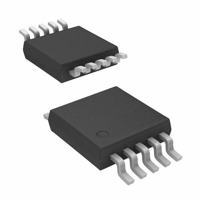
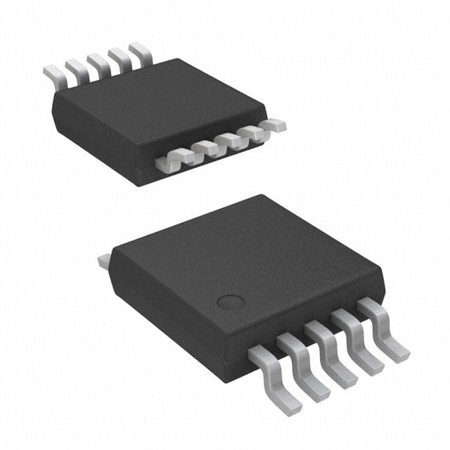
| 描述 | IC REG BOOST SWITCHED CAP 10MSOP稳压器—开关式稳压器 3.0/3.3V 20mA Dual Out Hi-Eff Chrg Pump |
| 产品分类 | |
| 品牌 | Texas Instruments |
| 产品手册 | |
| 产品图片 |
|
| rohs | 符合RoHS无铅 / 符合限制有害物质指令(RoHS)规范要求 |
| 产品系列 | 电源管理 IC,稳压器—开关式稳压器,Texas Instruments TPS60300DGSR- |
| 数据手册 | |
| 产品型号 | TPS60300DGSR |
| PWM类型 | - |
| 产品目录页面 | |
| 产品种类 | 稳压器—开关式稳压器 |
| 供应商器件封装 | 10-VSSOP |
| 关闭 | Shutdown |
| 其它名称 | 296-13410-6 |
| 包装 | Digi-Reel® |
| 单位重量 | 18.800 mg |
| 同步整流器 | 无 |
| 商标 | Texas Instruments |
| 安装类型 | 表面贴装 |
| 安装风格 | SMD/SMT |
| 封装 | Reel |
| 封装/外壳 | 10-TFSOP,10-MSOP(0.118",3.00mm 宽) |
| 封装/箱体 | VSSOP-10 |
| 工作温度 | -40°C ~ 125°C |
| 工作温度范围 | - 40 C to + 85 C |
| 工厂包装数量 | 2500 |
| 开关频率 | 700 kHz |
| 拓扑结构 | Boost |
| 最大工作温度 | + 85 C |
| 最大输入电压 | 1.8 V |
| 最小工作温度 | - 40 C |
| 最小输入电压 | 0.9 V |
| 标准包装 | 1 |
| 电压-输入 | 0.9 V ~ 1.8 V |
| 电压-输出 | 3.3V,1.8 V ~ 3.6 V |
| 电流-输出 | 40mA,20mA |
| 电源电压-最小 | 0.9 V |
| 电源电流 | 35 uA |
| 类型 | 升压(升压),切换电容(充电泵) |
| 系列 | TPS60300 |
| 负载调节 | 0.1 % / mA |
| 输入电压 | 0.9 V to 1.8 V |
| 输出数 | 2 |
| 输出电压 | 3.3 V |
| 输出电流 | 40 mA |
| 输出端数量 | 2 Output |
| 输出类型 | 固定和可调 |
| 频率-开关 | 700kHz |


- 商务部:美国ITC正式对集成电路等产品启动337调查
- 曝三星4nm工艺存在良率问题 高通将骁龙8 Gen1或转产台积电
- 太阳诱电将投资9.5亿元在常州建新厂生产MLCC 预计2023年完工
- 英特尔发布欧洲新工厂建设计划 深化IDM 2.0 战略
- 台积电先进制程称霸业界 有大客户加持明年业绩稳了
- 达到5530亿美元!SIA预计今年全球半导体销售额将创下新高
- 英特尔拟将自动驾驶子公司Mobileye上市 估值或超500亿美元
- 三星加码芯片和SET,合并消费电子和移动部门,撤换高东真等 CEO
- 三星电子宣布重大人事变动 还合并消费电子和移动部门
- 海关总署:前11个月进口集成电路产品价值2.52万亿元 增长14.8%


PDF Datasheet 数据手册内容提取
Product Sample & Technical Tools & Support & Reference Folder Buy Documents Software Community Design TPS60300,TPS60301,TPS60302,TPS60303 SLVS302B–DECEMBER2000–REVISEDOCTOBER2015 TPS6030x Single-Cell to 3-V or 3.3-V, 20-mA Dual Output, High-Efficiency Charge Pump 1 Features 3 Description • InputVoltageRangeFrom0.9Vto1.8V The TPS6030x devices are a family of switched- 1 voltage converters designed specifically for space- • Regulated3-Vor3.3-VOutputVoltage criticalbatterypoweredapplications. • Upto20-mAOutputCurrent The TPS6030x step-up, regulated charge pumps • HighPowerConversionEfficiency(upto90%) generate a 3-V (±4%) or 3.3-V (±4%) output voltage OveraWideOutputCurrentRange,Optimizedfor from a 0.9-V to 1.8-V input voltage (one alkaline, 1.2-VBatteryVoltage NiCd,orNiMHbattery). • AdditionalOutputWith2TimesV (OUT1) IN Only five small 1-µF ceramic capacitors are required • DeviceQuiescentCurrentLessThan35µA to build a complete high efficiency DC-DC charge • SupervisorIncluded;OpenDrainorPush-Pull pump converter. To achieve the high efficiency over a PowerGoodOutput wide input voltage range, the charge pump automatically selects between a 3× or 4× conversion • MinimumNumberofExternalComponents mode. – NoInductorsRequired Output 1 (OUT1) can deliver a maximum of 40 mA – OnlyFiveSmall,1-µFCeramicCapacitors from a 1-V input, with output 2 (OUT2) not loaded. Required OUT2 can deliver a maximum of 20 mA from a 1-V • LoadIsolatedFromBatteryDuringShutdown input, with OUT1 not loaded. Both outputs can be • Micro-Small10-PinMSOP(VSSOP)Package loaded at the same time, but the total output current of the first voltage doubler must not exceed 40 mA. For example, the load at output 1 is 20 mA and the 2 Applications loadatoutput2is10mA. • Pagers • Battery-PoweredToys DeviceInformation(1) • PortableMeasurementInstruments PARTNUMBER PACKAGE BODYSIZE(MAX) • Home-AutomationProducts TPS60300, TPS60301, VSSOP(10) 3.05mm×4.98mm • MedicalInstruments(LikeHearingInstruments) TPS60302, TPS60303 • MeteringApplicationsUsingMSP430Micro- Controller (1) For all available packages, see the orderable addendum at theendofthedatasheet. • PortableSmartCardReaders TypicalApplicationSchematic AlkalineBatteryOperatingTime Operating time (hours) with an alkaline battery (2000 mAh) until power good goes low at IL = 20 mA 1 An IMPORTANT NOTICE at the end of this data sheet addresses availability, warranty, changes, use in safety-critical applications, intellectualpropertymattersandotherimportantdisclaimers.PRODUCTIONDATA.
TPS60300,TPS60301,TPS60302,TPS60303 SLVS302B–DECEMBER2000–REVISEDOCTOBER2015 www.ti.com Table of Contents 1 Features.................................................................. 1 9.4 DeviceFunctionalModes........................................10 2 Applications........................................................... 1 10 ApplicationandImplementation........................ 11 3 Description............................................................. 1 10.1 ApplicationInformation..........................................11 4 RevisionHistory..................................................... 2 10.2 TypicalApplication ...............................................11 5 Description(continued)......................................... 3 11 PowerSupplyRecommendations..................... 18 6 DeviceComparisonTable..................................... 4 12 Layout................................................................... 18 12.1 LayoutGuidelines.................................................18 7 PinConfigurationandFunctions......................... 4 12.2 LayoutExample....................................................18 8 Specifications......................................................... 5 12.3 PowerDissipation.................................................19 8.1 AbsoluteMaximumRatings......................................5 13 DeviceandDocumentationSupport................. 20 8.2 ESDRatings ............................................................5 13.1 DeviceSupport......................................................20 8.3 RecommendedOperatingConditions.......................5 13.2 RelatedLinks........................................................20 8.4 ThermalInformation .................................................6 13.3 CommunityResources..........................................20 8.5 ElectricalCharacteristics...........................................6 13.4 Trademarks...........................................................20 8.6 TypicalCharacteristics..............................................8 13.5 ElectrostaticDischargeCaution............................20 9 DetailedDescription.............................................. 9 13.6 Glossary................................................................20 9.1 Overview...................................................................9 14 Mechanical,Packaging,andOrderable 9.2 FunctionalBlockDiagram.........................................9 Information........................................................... 20 9.3 FeatureDescription.................................................10 4 Revision History NOTE:Pagenumbersforpreviousrevisionsmaydifferfrompagenumbersinthecurrentversion. ChangesfromRevisionA(March2001)toRevisionB Page • AddedPinConfigurationandFunctionssection,ESDRatingstable,FeatureDescriptionsection,DeviceFunctional Modes,ApplicationandImplementationsection,PowerSupplyRecommendationssection,Layoutsection,Device andDocumentationSupportsection,andMechanical,Packaging,andOrderableInformationsection .............................. 1 2 SubmitDocumentationFeedback Copyright©2000–2015,TexasInstrumentsIncorporated ProductFolderLinks:TPS60300 TPS60301 TPS60302 TPS60303
TPS60300,TPS60301,TPS60302,TPS60303 www.ti.com SLVS302B–DECEMBER2000–REVISEDOCTOBER2015 5 Description (continued) The devices operate in the newly developed LinSkip mode. In this operating mode, the device switches seamlessly from the power saving, pulse-skip mode at light loads, to the low-noise, constant-frequency linear- regulationmode,whentheoutputcurrentexceedsthedevice-specificoutputcurrentthreshold. A power-good function supervises the output voltage of OUT2 and can be used for power-up and power-down sequencing.Powergood(PG)isofferedaseitheropen-drainorpush-pulloutput. Copyright©2000–2015,TexasInstrumentsIncorporated SubmitDocumentationFeedback 3 ProductFolderLinks:TPS60300 TPS60301 TPS60302 TPS60303
TPS60300,TPS60301,TPS60302,TPS60303 SLVS302B–DECEMBER2000–REVISEDOCTOBER2015 www.ti.com 6 Device Comparison Table DGS OUTPUT OUTPUT PARTNUMBER (1) PACKAGE CURRENT1 CURRENT2 OUTPUT OUTPUT FEATURE MARKING [mA] (2) [mA] (3) VOLTAGE1[V] VOLTAGE2[V] Open-drainpower- TPS60300DGS ALF 40 20 2×V 3.3 IN goodoutput Open-drainpower- TPS60301DGS ALG 40 20 2×V 3 IN goodoutput Push-pullpower- TPS60302DGS ALI 40 20 2×V 3.3 IN goodoutput Push-pullpower- TPS60303DGS ALK 40 20 2×V 3 IN goodoutput (1) TheDGSpackageisavailabletapedandreeled.AddRsuffixtodevicetype(forexample,TPS60300DGSR)toorderquantitiesof2500 devicesperreel. (2) IfOUT2isnotloaded. (3) IfOUT1isnotloaded. 7 Pin Configuration and Functions DGSPackage 10-PinVSSOP TopView PinFunctions PIN I/O DESCRIPTION NAME NO. C1+ 4 — PositivepinoftheflyingcapacitorC1F C1– 2 — NegativepinoftheflyingcapacitorC1F C2+ 7 — PositivepinoftheflyingcapacitorC2F C2– 8 — NegativepinoftheflyingcapacitorC2F Device-enableinput EN 1 I –EN=Lowdisablesthedevice.Outputandinputareisolatedinshutdownmode. –EN=Highenablesthedevice. GND 9 — Ground OUT1 5 O 2×V poweroutput.BypassOUT1toGNDwiththeoutputfiltercapacitorC . IN (OUT1) Regulated OUT2 6 O 3.3-Vpoweroutput(TPS60300,TPS60302)or3-Vpoweroutput(TPS60301,TPS60303),respectively BypassOUT2toGNDwiththeoutputfiltercapacitorC . (OUT2) Powergooddetectoroutput.AssoonasthevoltageonOUT2reachesabout98%ofitsnominalvaluethispin goeshigh. PG 10 O Open-drainoutputonTPS60300andTPS60301.Apull-upresistorshouldbeconnectedbetweenPGand OUT1orOUT2. Push-pulloutputstageonTPS60302andTPS60303 VIN 3 I Supplyinput.BypassV toGNDwitha≥1-µFcapacitor. IN 4 SubmitDocumentationFeedback Copyright©2000–2015,TexasInstrumentsIncorporated ProductFolderLinks:TPS60300 TPS60301 TPS60302 TPS60303
TPS60300,TPS60301,TPS60302,TPS60303 www.ti.com SLVS302B–DECEMBER2000–REVISEDOCTOBER2015 8 Specifications 8.1 Absolute Maximum Ratings Overoperatingfree-airtemperaturerange(unlessotherwisenoted) (1) MIN MAX UNIT V Inputvoltage(INtoGND)(2) –0.3 2 V IN V Outputvoltage(OUT1,OUT2,EN,PGtoGND)(2) –0.3 V OUT Voltage(C1+toGND) –0.3 V Voltage(C1–toGND,C2–toGND) –0.3 V Voltage(C2+toGND) –0.3 V I Outputcurrent(OUT1) 80 mA OUT I Outputcurrent(OUT2) 40 mA OUT T Maximumjunctiontemperature 150 °C J T Storagetemperature –55 150 °C stg (1) StressesbeyondthoselistedunderAbsoluteMaximumRatingsmaycausepermanentdamagetothedevice.Thesearestressratings only,whichdonotimplyfunctionaloperationofthedeviceattheseoranyotherconditionsbeyondthoseindicatedunderRecommended OperatingConditions.Exposuretoabsolute-maximum-ratedconditionsforextendedperiodsmayaffectdevicereliability. (2) ThevoltageatENandPGcanexceedINuptothemaximumratedvoltagewithoutincreasingtheleakagecurrentdrawnbythesepins. 8.2 ESD Ratings VALUE UNIT Human-bodymodel(HBM),perANSI/ESDA/JEDECJS-001(1) ±2000 V(ESD) Electrostaticdischarge Charged-devicemodel(CDM),perJEDECspecificationJESD22- V C101(2) ±500 (1) JEDECdocumentJEP155statesthat500-VHBMallowssafemanufacturingwithastandardESDcontrolprocess. (2) JEDECdocumentJEP157statesthat250-VCDMallowssafemanufacturingwithastandardESDcontrolprocess. 8.3 Recommended Operating Conditions Overoperatingfree-airtemperaturerange(unlessotherwisenoted) MIN NOM MAX UNIT V Inputvoltage 0.9 1.8 V IN I Outputcurrent(OUT2) 20 mA OUT(OUT2) I Outputcurrent(OUT1) 40 mA OUT(OUT1) C Inputcapacitor 1 µF IN C1F,C2F Flyingcapacitors 1 µF C Outputcapacitor 1 µF OUT(1) C Outputcapacitor 1 µF OUT(2) T Operatingjunctiontemperature –40 125 °C J Copyright©2000–2015,TexasInstrumentsIncorporated SubmitDocumentationFeedback 5 ProductFolderLinks:TPS60300 TPS60301 TPS60302 TPS60303
TPS60300,TPS60301,TPS60302,TPS60303 SLVS302B–DECEMBER2000–REVISEDOCTOBER2015 www.ti.com 8.4 Thermal Information TPS6030x THERMALMETRIC(1) DGS(VSSOP) UNIT 10PINS R Junction-to-ambientthermalresistance 156.1 °C/W θJA R Junction-to-case(top)thermalresistance 53.0 °C/W θJC(top) R Junction-to-boardthermalresistance 75.5 °C/W θJB ψ Junction-to-topcharacterizationparameter 5.4 °C/W JT ψ Junction-to-boardcharacterizationparameter 74.3 °C/W JB (1) Formoreinformationabouttraditionalandnewthermalmetrics,seetheSemiconductorandICPackageThermalMetricsapplication report(SPRA953). 8.5 Electrical Characteristics C =C1F=C2F=C =C =1µF,T =–40°Cto85°C,V =1V,V =V (unlessotherwisenoted) IN (OUT1) (OUT2) C IN (EN) IN PARAMETER TESTCONDITIONS MIN TYP MAX UNIT V Supplyvoltagerange 0.9 1.8 V IN I V ≥1.1V,I =0mA,I = OUT(OUT1) IN OUT(OUT2) (PG,1) 40 0mA mA V =0.9V,I =0mA,I = IN OUT(OUT2) (PG,1) 20 Maximumoutputcurrentfor 0mA I TPS60300,TPS60302 V ≥1.1V,I =0mA,I = OUT(OUT2) IN OUT(OUT1) (PG,1) 20 0mA mA V =0.9V,I =0mA,I = IN OUT(OUT1) (PG,1) 10 0mA I V ≥1.1V,I =0mA,I = OUT(OUT1) IN OUT(OUT2) (PG,1) 40 0mA mA V =0.9V,I )=0mA,I = IN OUT(OUT2 (PG,1) 20 Maximumoutputcurrentfor 0mA I TPS60301,TPS60303 V ≥1V,I =0mA,I =0 OUT(OUT2) IN OUT(OUT1) (PG,1) 20 mA mA V =0.9V,I =0mA,I = IN OUT(OUT1) (PG,1) 12 0mA V 1.1V<V <1.8V,I )=0mA, OUT(OUT2) IN OUT(OUT1 3.17 3.30 3.43 OutputvoltageforTPS60300, 0<IOUT(OUT2)<20mA V TPS60302 0.9V<V <1.1V,I =0mA, IN OUT(OUT1) 3.17 3.30 3.43 I <10mA OUT(OUT2) V 1.0V<V <1.8V,I =0mA, OUT(OUT2) IN OUT(OUT1) 2.88 3 3.12 OutputvoltageforTPS60301, 0<IOUT(OUT2)<20mA V TPS60303 V >1.65V,I =0mA, IN OUT(OUT1) 2.88 3 3.15 25µA<I <20mA OUT(OUT2) VP–P Output OUT2 IOUT(OUT2)=20mA,IOUT(OUT1)=0mA 20 mV voltageripple OUT1 I =40mA,I =0mA 40 P–P OUT(OUT1) OUT(OUT2) I Quiescentcurrent(no-loadinput Q I =0mA,V =1.8V 35 70 µA current) OUT(OUT) IN I V =1.8V,V =0V(1) 0.05 2.5 (SD) IN (EN) Shutdownsupplycurrent µA V =1.8V,V =0V,T =25°C(1) 0.5 IN (EN) C f Internalswitchingfrequency 470 700 900 kHz OSC V ENinputlowvoltage V =0.9Vto1.8V 0.3×V V IL(EN) IN IN V ENinputhighvoltage V =0.9Vto1.8V 0.7×V V IH(EN) IN IN V =0VorV orV or I ENinputleakagecurrent (EN) IN OUT(OUT2) 0.01 0.1 µA lkg V OUT(OUT1) LinSkipswitchingthreshold V =1.25V 7.5 mA IN (1) OUT1notloaded.IfOUT1isconnectedtoGNDthrougharesistor,leakagecurrentwillbeincreased. 6 SubmitDocumentationFeedback Copyright©2000–2015,TexasInstrumentsIncorporated ProductFolderLinks:TPS60300 TPS60301 TPS60302 TPS60303
TPS60300,TPS60301,TPS60302,TPS60303 www.ti.com SLVS302B–DECEMBER2000–REVISEDOCTOBER2015 Electrical Characteristics (continued) C =C1F=C2F=C =C =1µF,T =–40°Cto85°C,V =1V,V =V (unlessotherwisenoted) IN (OUT1) (OUT2) C IN (EN) IN PARAMETER TESTCONDITIONS MIN TYP MAX UNIT V =0V 5 20 50 OUT(OUT2) Shortcircuitcurrent V =1.8V mA IN V =0V 2 80 150 OUT(OUT1) Output V =3V,V =nominal, leakage OUT2 O(OUT1) OUT(OUT2) 1 µA EN=0V current V =1.25V,T =25°C,2mA< Outputloadregulation IN C 0.1 %/mA I <20mA OUT(OUT2) 1V<V <1.65V;T =25°C, Outputlineregulation IN C 0.75 %/V I =10mA OUT(OUT) No-loadstart-uptime 400 µs Impedanceoffirstchargepump 4 Ω stage V ≥1.1V 165 IN Start-upperformanceatOUT2 V ≥1V 330 Ω (minimumstart-uploadresistance) IN V =0.9V 1000 IN Start-upperformanceatOUT1 V =1V 500 Ω (minimumstart-uploadresistance) IN FORPOWERGOODCOMPARATOR: V Powergoodtripvoltage V rampingpositive V –2% V V (PG) OUT OUT OUT V Powergoodtripvoltagehysteresis V rampingnegative 10% hys OUT V Powergoodoutputvoltagelow V =0V,I =1.6mA 0.3 OL OUT (PG) V I Powergood TPS60300 V =3.3V,V =3.3V 0.01 0.1 lkg OUT (PG) leakage current TPS60301 VOUT=3V,V(PG)=3V 0.01 0.1 µA V Powergood TPS60303 3 OH output I =–5mA V (PG) voltagehigh TPS60302 2.7 I Output OUT(PG,0) currentat Alldevices V =0V 1.6 mA powergood (PG) (sink) R(PG,1) Output TPS60302, V =V 15 Ω resistanceat TPS60303 (PG) O(OUT2) R powergood Alldevices V =0V 100 Ω (PG,0) (PG) Copyright©2000–2015,TexasInstrumentsIncorporated SubmitDocumentationFeedback 7 ProductFolderLinks:TPS60300 TPS60301 TPS60302 TPS60303
TPS60300,TPS60301,TPS60302,TPS60303 SLVS302B–DECEMBER2000–REVISEDOCTOBER2015 www.ti.com 8.6 Typical Characteristics Figure1.TPS6030x Figure2.SwitchingFrequencyvsInputVoltage QuiescentCurrentvsInputVoltage 8 SubmitDocumentationFeedback Copyright©2000–2015,TexasInstrumentsIncorporated ProductFolderLinks:TPS60300 TPS60301 TPS60302 TPS60303
TPS60300,TPS60301,TPS60302,TPS60303 www.ti.com SLVS302B–DECEMBER2000–REVISEDOCTOBER2015 9 Detailed Description 9.1 Overview The TPS6030x charge pumps are voltage quadruplers that provide a regulated 3.3-V or 3-V output from a 0.9-V to 1.8-V input. They deliver a maximum load current of 20 mA. Designed specifically for space critical battery powered applications, the complete converter requires only five external capacitors and enables the design to use low-cost, small-sized, 1-µF ceramic capacitors. The TPS6030x circuits consist of an oscillator, a voltage reference, an internal resistive feedback circuit, an error amplifier, two charge pump stages with MOSFETswitches,ashutdownandstart-upcircuit,andacontrolcircuit. 9.2 Functional Block Diagram Copyright©2000–2015,TexasInstrumentsIncorporated SubmitDocumentationFeedback 9 ProductFolderLinks:TPS60300 TPS60301 TPS60302 TPS60303
TPS60300,TPS60301,TPS60302,TPS60303 SLVS302B–DECEMBER2000–REVISEDOCTOBER2015 www.ti.com 9.3 Feature Description 9.3.1 Power-GoodDetector The power-good output is an open-drain output on the TPS60300 and TPS60301 or a push-pull output on the TPS60302 and TPS60303. The PG-output pulls low when the output of OUT2 is out of regulation. When the output rises to within 98% of regulation, the power-good output goes active high. In shutdown, power-good is pulled low. In normal operation, an external pullup resistor with the TPS60300 and TPS60301 is typically used to connect the PG pin to V . The resistor should be in the 100-kΩ to 1-MΩ range. If the PG output is not used, it OUT should remain unconnected. Output current at PG (TPS60302, TPS60303) will reduce maximum output current atOUT2. 9.4 Device Functional Modes 9.4.1 Start-upProcedure The device is enabled when EN is set from logic low to logic high. CP1 will first enter a DC start-up mode during which the capacitor on OUT1 is charged up to about V . After that, it starts switching to boost the voltage further IN up to about two times V . CP2 will then follow and charge up the capacitor on OUT2 to about the voltage on IN OUT1,afterthat,itwillalsostartswitchingandboostupthevoltagetoitsnominalvalue.ENmustnotexceedthe highestvoltageappliedtothedevice. NOTE Duringstart-upwithV =0V,thehighestvoltageistheinputvoltage. OUT 9.4.2 Shutdown Driving EN low disables the converter. This disables all internal circuits, reducing input current to only 0.05 µA. Leakage current drawn from the output pins OUT1 and OUT2 is a maximum of 1 µA. The device exits shutdown once EN is set high (see Start-up Procedure). The typical no-load, start-up time is 400 µs. When the device is disabled, the load is isolated from the input. This is an important feature in battery operated products because it extendsthebatteryshelflife. 10 SubmitDocumentationFeedback Copyright©2000–2015,TexasInstrumentsIncorporated ProductFolderLinks:TPS60300 TPS60301 TPS60302 TPS60303
TPS60300,TPS60301,TPS60302,TPS60303 www.ti.com SLVS302B–DECEMBER2000–REVISEDOCTOBER2015 10 Application and Implementation NOTE Information in the following applications sections is not part of the TI component specification, and TI does not warrant its accuracy or completeness. TI’s customers are responsible for determining suitability of components for their purposes. Customers should validateandtesttheirdesignimplementationtoconfirmsystemfunctionality. 10.1 Application Information The TPS6030x is a switched capacitor voltage converter providing low noise, constant-frequency linear regulation mode. It supports regulated output voltages of 3 V and 3.3 V from a 0.9-V to 1.8-V input voltage range. 10.2 Typical Application Figure3. TypicalOperatingCircuit 10.2.1 DesignRequirements The complete charge pump circuitry requires no inductors and only five small 1-µF ceramic capacitors. It is possibletoonlyuse1-µFcapacitorsofthesametype. Copyright©2000–2015,TexasInstrumentsIncorporated SubmitDocumentationFeedback 11 ProductFolderLinks:TPS60300 TPS60301 TPS60302 TPS60303
TPS60300,TPS60301,TPS60302,TPS60303 SLVS302B–DECEMBER2000–REVISEDOCTOBER2015 www.ti.com Typical Application (continued) 10.2.2 DetailedDesignProcedure 10.2.2.1 CapacitorSelection The values of the five external capacitors of the TPS6030x charge pumps are closely linked to the required outputcurrentandtheoutputnoiseandripplerequirements. Forthemaximumoutputcurrentandbestperformance,fiveceramiccapacitorswithaminimumvalueof1 µFare recommended. This value is necessary to assure a stable operation of the system due to the linear mode. For lower currents or higher allowed output voltage ripple, other capacitors can be used. With flying capacitors lower than1µF,themaximumoutputpowerwilldecrease.Thismeans that the device will work in the linear mode with loweroutputcurrents. Theinputcapacitorimprovessystemefficiencybyreducingtheinputimpedanceandstabilizingtheinputcurrent. Theminimumrequiredcapacitanceoftheoutputcapacitor(C )thatcanbeselectedis1µF.Dependingonthe OUT maximum allowed output ripple voltage, larger values can be chosen. Table 1 shows capacitor values recommendedforlowoutputvoltagerippleoperation.Arecommendationisgivenforthesmallestsize. Table1.RecommendedCapacitorValuesforLowOutputVoltageRipple Operation C C C IN XF OUT V I V [mV] IN OUT(OUT2) [µF] [µF] [µF] P-P [V] [mA] At20mA/V =1.1V IN CERAMIC CERAMIC CERAMIC 0.9...1.8 0...20 1 1 1 16 0.9...1.8 0...20 1 1 2.2 10 0.9...1.8 0…20 1 1 10//0.1 6 Table2.RecommendedCapacitors MANUFACTURER PARTNUMBER SIZE CAPACITANCE TYPE UMK212BJ104MG 805 0.1µF Ceramic LMK212BJ105KG 805 1µF Ceramic TaiyoYuden LMK212BJ225MG 805 2.2µF Ceramic JMK316BJ475KL 1206 4.7µF Ceramic 0805ZC105KAT2A 805 1µF Ceramic AVX 1206ZC225KAT2A 1206 2.2µF Ceramic Table 3 lists the manufacturers of recommended capacitors. However, ceramic capacitors will provide the lowest outputvoltagerippleduetotheirtypicallylowerESR. Table3.RecommendedCapacitorManufacturers MANUFACTURER CAPACITORTYPE INTERNET TaiyoYuden X7R/X5Rceramic www.t-yuden.com AVX X7R/X5Rceramic www.avxcorp.com Vishay X7R/X5Rceramic www.vishay.com Kemet X7R/X5Rceramic www.kemet.com TDK X7R/X5Rceramic www.component.tdk.com 12 SubmitDocumentationFeedback Copyright©2000–2015,TexasInstrumentsIncorporated ProductFolderLinks:TPS60300 TPS60301 TPS60302 TPS60303
TPS60300,TPS60301,TPS60302,TPS60303 www.ti.com SLVS302B–DECEMBER2000–REVISEDOCTOBER2015 10.2.2.2 OutputFilterDesign The power-good output is capable of driving light loads up to 5 mA (see Figure 4). Therefore, the output resistanceofthepower-goodpin,inadditionwithanoutputcapacitor,canbeusedasanRC-filter. Figure4. TPS60302,TPS60303Push-PullPower-GoodOutput-StageasFilteredSupply DuetoR ,anoutputfiltercaneasilybeformedwithanoutputcapacitor(C ).Cut-offfrequencyisgivenby: (PG,1) PG 1 ƒ = c 2pR C (PG,1) (PG) (1) V(PG,1) 1 andratio V /V is: = OUT IN VO(OUT2) 1+(2pƒR C )2 (PG,1) (PG) (2) withR =15Ω,C =0.1µFandf=600kHz(atnominalswitchingfrequency) (PG,1) (PG) V (PG,1) =0.175 V O(OUT2) (3) Load current sourced by power-good output reduces maximum output current at OUT2. During start-up (power good going high) current charging C will discharge C . Therefore, C must not be larger than 0.1 (PG) (OUT2) (PG) C or the device will not start. By charging C through C , the output voltage at OUT2 will decrease. If (OUT2) (PG) (OUT2) the capacitance of C is to large, the circuit will detect power bad. The power-good output will go low and (PG) discharge C . Then the cycle starts again. Figure 5 shows a configuration with an LC-post filter to further (PG) reduceoutputrippleandnoise. Copyright©2000–2015,TexasInstrumentsIncorporated SubmitDocumentationFeedback 13 ProductFolderLinks:TPS60300 TPS60301 TPS60302 TPS60303
TPS60300,TPS60301,TPS60302,TPS60303 SLVS302B–DECEMBER2000–REVISEDOCTOBER2015 www.ti.com Figure5. LC-PostFilter Table4.RecommendedValuesforLowestOutputVoltageRipple VIN IO(OUT2) CIN[µF] CXF[µF] COUT[µF] L [µH] CP[µF] VP(OUT) [V] [mA] CERAMIC CERAMIC CERAMIC P CERAMIC VP-P[mV] 0.9...1.8 20 1 1 1 0.1 0.1(X7R) 16 0.9...1.8 20 1 1 1 0.1 1//0.1(X7R) 12 0.9...1.8 20 1 1 1 1 0.1(X7R) 14 0.9...1.8 20 1 1 10 1 1//0.1(X7R) 3 Figure6. ApplicationWithMSP430;PGasSupplyforAnalogCircuits 14 SubmitDocumentationFeedback Copyright©2000–2015,TexasInstrumentsIncorporated ProductFolderLinks:TPS60300 TPS60301 TPS60302 TPS60303
TPS60300,TPS60301,TPS60302,TPS60303 www.ti.com SLVS302B–DECEMBER2000–REVISEDOCTOBER2015 10.2.3 ApplicationCurves Figure7.TPS60300,TPS60302 Figure8.TPS60301,TPS60303 EfficiencyvsOutputCurrent EfficiencyvsOutputCurrent Figure9.TPS60300 Figure10.TPS60300,TPS60302 SupplyCurrentvsOutputCurrent OutputVoltage(OUT2)vsOutputCurrent(OUT2) Figure11.TPS60301,TPS60303 Figure12.TPS60300,TPS60302 OutputVoltage(OUT2)vsOutputCurrent(OUT2) OutputVoltage(OUT1)vsOutputCurrent(OUT1) Copyright©2000–2015,TexasInstrumentsIncorporated SubmitDocumentationFeedback 15 ProductFolderLinks:TPS60300 TPS60301 TPS60302 TPS60303
TPS60300,TPS60301,TPS60302,TPS60303 SLVS302B–DECEMBER2000–REVISEDOCTOBER2015 www.ti.com Figure13.TPS60300,TPS60302 Figure14.TPS60300,TPS60302 OutputVoltage(OUT2)vsInputVoltage OutputVoltage(OUT2)vsInputVoltage Figure15.TPS6030x Figure16.TPS60300,TPS60302 OutputVoltage(OUT1)vsInputVoltage OutputVoltage(OUT2)vsFree-AirTemperature Figure17.TPS60301,TPS60303 Figure18.TPS6030x OutputVoltage(OUT2)vsFree-AirTemperature OutputVoltageRipple(OUT2) 16 SubmitDocumentationFeedback Copyright©2000–2015,TexasInstrumentsIncorporated ProductFolderLinks:TPS60300 TPS60301 TPS60302 TPS60303
TPS60300,TPS60301,TPS60302,TPS60303 www.ti.com SLVS302B–DECEMBER2000–REVISEDOCTOBER2015 Figure19.TPS60300,TPS60302 Figure20.TPS60301,TPS60303 MinimumInputVoltagevsOutputCurrent MinimumInputVoltagevsOutputCurrent Figure21.Start-UpTimingEnable Figure22.LoadTransientResponse Figure23.LineTransientResponse Copyright©2000–2015,TexasInstrumentsIncorporated SubmitDocumentationFeedback 17 ProductFolderLinks:TPS60300 TPS60301 TPS60302 TPS60303
TPS60300,TPS60301,TPS60302,TPS60303 SLVS302B–DECEMBER2000–REVISEDOCTOBER2015 www.ti.com 11 Power Supply Recommendations The TPS6030x devices have no special requirements for their input power supply. The output currents of the input power supply must be rated according to the supply voltage, output voltage, and output current of the TPS6030x. 12 Layout 12.1 Layout Guidelines All capacitors must be soldered as close as possible to the IC. A PCB layout proposal for a two-layer board is shown in Figure 24. Care has been taken to connect all capacitors as close as possible to the circuit to achieve optimized output voltage ripple performance. The bottom layer is not shown in Figure 24. It only consists of a ground-planewithasingletrackbetweenthetwoviasthatcanbeseenintheleftpartofthetoplayer. 12.2 Layout Example Figure24. RecommendedPCBLayoutforTPS6030x(TopLayer) 18 SubmitDocumentationFeedback Copyright©2000–2015,TexasInstrumentsIncorporated ProductFolderLinks:TPS60300 TPS60301 TPS60302 TPS60303
TPS60300,TPS60301,TPS60302,TPS60303 www.ti.com SLVS302B–DECEMBER2000–REVISEDOCTOBER2015 12.3 Power Dissipation The thermal resistance of the unsoldered package is R = 294°C/W. Soldered on the EVM, a typical thermal θJA resistanceofR =200°C/Wwasmeasured. θJA(EVM) ThethermalresistancecanbecalculatedasshowninEquation4. T -T R = J A qJA P D where • T isthejunctiontemperature. J • T istheambienttemperature. A • P isthepowerthatneedstobedissipatedbythedevice. (4) D ThemaximumpowerdissipationcanbecalculatedasshowninEquation5. P =V ×I –V ×I =V ×[(3×I +I ]–V ×I (5) D IN IN OUT OUT IN(max) OUT (SUPPLY) OUT OUT Themaximumpowerdissipationhappenswithmaximuminputvoltageandmaximumoutputcurrent: Atmaximumloadthesupplycurrentisapproximately2mA. P =1.8V×(3×20mA+2mA)–3.3V×20mA=46mW. (6) D With this maximum rating and the thermal resistance of the device on the EVM, the maximum temperature rise aboveambienttemperaturecanbecalculatedasshowninEquation7. ΔT =R ×P =200°C/W×46mW=10°C (7) J θJA D ThismeansthatinternaldissipationincreasesT by10°C. J Thejunctiontemperatureofthedevicemustnotexceed125°C. ThismeanstheICcaneasilybeusedatambienttemperaturesasseeninEquation8. T =T –ΔT =125°C–10°C=115°C (8) A J(max) J Copyright©2000–2015,TexasInstrumentsIncorporated SubmitDocumentationFeedback 19 ProductFolderLinks:TPS60300 TPS60301 TPS60302 TPS60303
TPS60300,TPS60301,TPS60302,TPS60303 SLVS302B–DECEMBER2000–REVISEDOCTOBER2015 www.ti.com 13 Device and Documentation Support 13.1 Device Support 13.1.1 Third-PartyProductsDisclaimer TI'S PUBLICATION OF INFORMATION REGARDING THIRD-PARTY PRODUCTS OR SERVICES DOES NOT CONSTITUTE AN ENDORSEMENT REGARDING THE SUITABILITY OF SUCH PRODUCTS OR SERVICES OR A WARRANTY, REPRESENTATION OR ENDORSEMENT OF SUCH PRODUCTS OR SERVICES, EITHER ALONEORINCOMBINATIONWITHANYTIPRODUCTORSERVICE. 13.2 Related Links The table below lists quick access links. Categories include technical documents, support and community resources,toolsandsoftware,andquickaccesstosampleorbuy. Table5.RelatedLinks TECHNICAL TOOLS& SUPPORT& PARTS PRODUCTFOLDER SAMPLE&BUY DOCUMENTS SOFTWARE COMMUNITY TPS60300 Clickhere Clickhere Clickhere Clickhere Clickhere TPS60301 Clickhere Clickhere Clickhere Clickhere Clickhere TPS60302 Clickhere Clickhere Clickhere Clickhere Clickhere TPS60303 Clickhere Clickhere Clickhere Clickhere Clickhere 13.3 Community Resources The following links connect to TI community resources. Linked contents are provided "AS IS" by the respective contributors. They do not constitute TI specifications and do not necessarily reflect TI's views; see TI's Terms of Use. TIE2E™OnlineCommunity TI'sEngineer-to-Engineer(E2E)Community.Createdtofostercollaboration amongengineers.Ate2e.ti.com,youcanaskquestions,shareknowledge,exploreideasandhelp solveproblemswithfellowengineers. DesignSupport TI'sDesignSupport QuicklyfindhelpfulE2Eforumsalongwithdesignsupporttoolsand contactinformationfortechnicalsupport. 13.4 Trademarks E2EisatrademarkofTexasInstruments. Allothertrademarksarethepropertyoftheirrespectiveowners. 13.5 Electrostatic Discharge Caution Thesedeviceshavelimitedbuilt-inESDprotection.Theleadsshouldbeshortedtogetherorthedeviceplacedinconductivefoam duringstorageorhandlingtopreventelectrostaticdamagetotheMOSgates. 13.6 Glossary SLYZ022—TIGlossary. Thisglossarylistsandexplainsterms,acronyms,anddefinitions. 14 Mechanical, Packaging, and Orderable Information The following pages include mechanical, packaging, and orderable information. This information is the most current data available for the designated devices. This data is subject to change without notice and revision of thisdocument.Forbrowser-basedversionsofthisdatasheet,refertotheleft-handnavigation. 20 SubmitDocumentationFeedback Copyright©2000–2015,TexasInstrumentsIncorporated ProductFolderLinks:TPS60300 TPS60301 TPS60302 TPS60303
PACKAGE OPTION ADDENDUM www.ti.com 6-Feb-2020 PACKAGING INFORMATION Orderable Device Status Package Type Package Pins Package Eco Plan Lead/Ball Finish MSL Peak Temp Op Temp (°C) Device Marking Samples (1) Drawing Qty (2) (6) (3) (4/5) TPS60300DGS ACTIVE VSSOP DGS 10 80 Green (RoHS NIPDAU Level-1-260C-UNLIM -40 to 85 ALF & no Sb/Br) TPS60300DGSG4 ACTIVE VSSOP DGS 10 80 Green (RoHS NIPDAU Level-1-260C-UNLIM -40 to 85 ALF & no Sb/Br) TPS60300DGSR ACTIVE VSSOP DGS 10 2500 Green (RoHS NIPDAU Level-1-260C-UNLIM -40 to 85 ALF & no Sb/Br) TPS60300DGSRG4 ACTIVE VSSOP DGS 10 2500 Green (RoHS NIPDAU Level-1-260C-UNLIM -40 to 85 ALF & no Sb/Br) TPS60301DGS ACTIVE VSSOP DGS 10 80 Green (RoHS NIPDAU Level-1-260C-UNLIM -40 to 85 ALG & no Sb/Br) TPS60301DGSR ACTIVE VSSOP DGS 10 2500 Green (RoHS NIPDAU Level-1-260C-UNLIM -40 to 85 ALG & no Sb/Br) TPS60302DGS ACTIVE VSSOP DGS 10 80 Green (RoHS NIPDAU Level-1-260C-UNLIM -40 to 85 ALI & no Sb/Br) TPS60302DGSR ACTIVE VSSOP DGS 10 2500 Green (RoHS NIPDAU Level-1-260C-UNLIM -40 to 85 ALI & no Sb/Br) TPS60303DGSR ACTIVE VSSOP DGS 10 2500 Green (RoHS NIPDAU Level-1-260C-UNLIM -40 to 85 ALK & no Sb/Br) (1) The marketing status values are defined as follows: ACTIVE: Product device recommended for new designs. LIFEBUY: TI has announced that the device will be discontinued, and a lifetime-buy period is in effect. NRND: Not recommended for new designs. Device is in production to support existing customers, but TI does not recommend using this part in a new design. PREVIEW: Device has been announced but is not in production. Samples may or may not be available. OBSOLETE: TI has discontinued the production of the device. (2) RoHS: TI defines "RoHS" to mean semiconductor products that are compliant with the current EU RoHS requirements for all 10 RoHS substances, including the requirement that RoHS substance do not exceed 0.1% by weight in homogeneous materials. Where designed to be soldered at high temperatures, "RoHS" products are suitable for use in specified lead-free processes. TI may reference these types of products as "Pb-Free". RoHS Exempt: TI defines "RoHS Exempt" to mean products that contain lead but are compliant with EU RoHS pursuant to a specific EU RoHS exemption. Green: TI defines "Green" to mean the content of Chlorine (Cl) and Bromine (Br) based flame retardants meet JS709B low halogen requirements of <=1000ppm threshold. Antimony trioxide based flame retardants must also meet the <=1000ppm threshold requirement. (3) MSL, Peak Temp. - The Moisture Sensitivity Level rating according to the JEDEC industry standard classifications, and peak solder temperature. Addendum-Page 1
PACKAGE OPTION ADDENDUM www.ti.com 6-Feb-2020 (4) There may be additional marking, which relates to the logo, the lot trace code information, or the environmental category on the device. (5) Multiple Device Markings will be inside parentheses. Only one Device Marking contained in parentheses and separated by a "~" will appear on a device. If a line is indented then it is a continuation of the previous line and the two combined represent the entire Device Marking for that device. (6) Lead/Ball Finish - Orderable Devices may have multiple material finish options. Finish options are separated by a vertical ruled line. Lead/Ball Finish values may wrap to two lines if the finish value exceeds the maximum column width. Important Information and Disclaimer:The information provided on this page represents TI's knowledge and belief as of the date that it is provided. TI bases its knowledge and belief on information provided by third parties, and makes no representation or warranty as to the accuracy of such information. Efforts are underway to better integrate information from third parties. TI has taken and continues to take reasonable steps to provide representative and accurate information but may not have conducted destructive testing or chemical analysis on incoming materials and chemicals. TI and TI suppliers consider certain information to be proprietary, and thus CAS numbers and other limited information may not be available for release. In no event shall TI's liability arising out of such information exceed the total purchase price of the TI part(s) at issue in this document sold by TI to Customer on an annual basis. Addendum-Page 2
PACKAGE MATERIALS INFORMATION www.ti.com 5-May-2019 TAPE AND REEL INFORMATION *Alldimensionsarenominal Device Package Package Pins SPQ Reel Reel A0 B0 K0 P1 W Pin1 Type Drawing Diameter Width (mm) (mm) (mm) (mm) (mm) Quadrant (mm) W1(mm) TPS60300DGSR VSSOP DGS 10 2500 330.0 12.4 5.3 3.4 1.4 8.0 12.0 Q1 TPS60301DGSR VSSOP DGS 10 2500 330.0 12.4 5.3 3.4 1.4 8.0 12.0 Q1 TPS60302DGSR VSSOP DGS 10 2500 330.0 12.4 5.3 3.4 1.4 8.0 12.0 Q1 TPS60303DGSR VSSOP DGS 10 2500 330.0 12.4 5.3 3.4 1.4 8.0 12.0 Q1 PackMaterials-Page1
PACKAGE MATERIALS INFORMATION www.ti.com 5-May-2019 *Alldimensionsarenominal Device PackageType PackageDrawing Pins SPQ Length(mm) Width(mm) Height(mm) TPS60300DGSR VSSOP DGS 10 2500 350.0 350.0 43.0 TPS60301DGSR VSSOP DGS 10 2500 350.0 350.0 43.0 TPS60302DGSR VSSOP DGS 10 2500 350.0 350.0 43.0 TPS60303DGSR VSSOP DGS 10 2500 350.0 350.0 43.0 PackMaterials-Page2
IMPORTANTNOTICEANDDISCLAIMER TI PROVIDES TECHNICAL AND RELIABILITY DATA (INCLUDING DATASHEETS), DESIGN RESOURCES (INCLUDING REFERENCE DESIGNS), APPLICATION OR OTHER DESIGN ADVICE, WEB TOOLS, SAFETY INFORMATION, AND OTHER RESOURCES “AS IS” AND WITH ALL FAULTS, AND DISCLAIMS ALL WARRANTIES, EXPRESS AND IMPLIED, INCLUDING WITHOUT LIMITATION ANY IMPLIED WARRANTIES OF MERCHANTABILITY, FITNESS FOR A PARTICULAR PURPOSE OR NON-INFRINGEMENT OF THIRD PARTY INTELLECTUAL PROPERTY RIGHTS. These resources are intended for skilled developers designing with TI products. You are solely responsible for (1) selecting the appropriate TI products for your application, (2) designing, validating and testing your application, and (3) ensuring your application meets applicable standards, and any other safety, security, or other requirements. These resources are subject to change without notice. TI grants you permission to use these resources only for development of an application that uses the TI products described in the resource. Other reproduction and display of these resources is prohibited. No license is granted to any other TI intellectual property right or to any third party intellectual property right. TI disclaims responsibility for, and you will fully indemnify TI and its representatives against, any claims, damages, costs, losses, and liabilities arising out of your use of these resources. TI’s products are provided subject to TI’s Terms of Sale (www.ti.com/legal/termsofsale.html) or other applicable terms available either on ti.com or provided in conjunction with such TI products. TI’s provision of these resources does not expand or otherwise alter TI’s applicable warranties or warranty disclaimers for TI products. Mailing Address: Texas Instruments, Post Office Box 655303, Dallas, Texas 75265 Copyright © 2020, Texas Instruments Incorporated