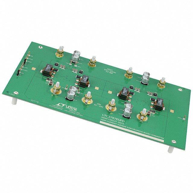
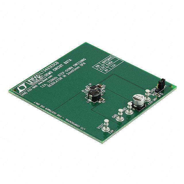
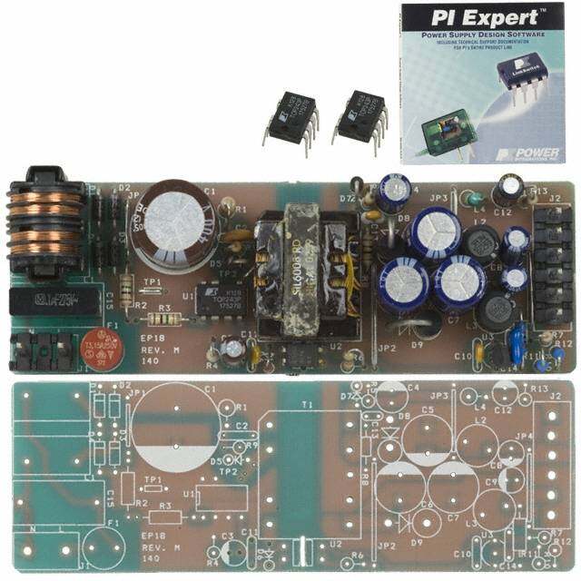
ICGOO在线商城 > 开发板,套件,编程器 > 评估板 - DC/DC 与 AC/DC(离线)SMPS > TPS5430EVM-173
- 型号: TPS5430EVM-173
- 制造商: Texas Instruments
- 库位|库存: xxxx|xxxx
- 要求:
| 数量阶梯 | 香港交货 | 国内含税 |
| +xxxx | $xxxx | ¥xxxx |
查看当月历史价格
查看今年历史价格
TPS5430EVM-173产品简介:
ICGOO电子元器件商城为您提供TPS5430EVM-173由Texas Instruments设计生产,在icgoo商城现货销售,并且可以通过原厂、代理商等渠道进行代购。 TPS5430EVM-173价格参考¥408.82-¥408.82。Texas InstrumentsTPS5430EVM-173封装/规格:评估板 - DC/DC 与 AC/DC(离线)SMPS, TPS5430 SWIFT™ DC/DC, Step Down 1, Non-Isolated Outputs Evaluation Board。您可以下载TPS5430EVM-173参考资料、Datasheet数据手册功能说明书,资料中有TPS5430EVM-173 详细功能的应用电路图电压和使用方法及教程。
| 参数 | 数值 |
| 产品目录 | 编程器,开发系统半导体 |
| 描述 | EVALUATION MODULE FOR TPS5430电源管理IC开发工具 Step Down Conv Mod |
| 产品分类 | |
| 品牌 | Texas Instruments |
| 产品手册 | |
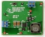
| 产品图片 |
|
| rohs | 否含铅 / 不受限制有害物质指令(RoHS)规范要求限制 |
| 产品系列 | 电源管理IC开发工具,Texas Instruments TPS5430EVM-173SWIFT™ |
| 数据手册 | 点击此处下载产品Datasheethttp://www.ti.com/lit/pdf/slvu157 |
| 产品型号 | TPS5430EVM-173 |
| 主要用途 | DC/DC,步降 |
| 产品 | Evaluation Boards |
| 产品培训模块 | http://www.digikey.cn/PTM/IndividualPTM.page?site=cn&lang=zhs&ptm=16804 |
| 产品目录页面 | |
| 产品种类 | 电源管理IC开发工具 |
| 使用的IC/零件 | TPS5430 |
| 其它名称 | 296-19640 |
| 制造商产品页 | http://www.ti.com/general/docs/suppproductinfo.tsp?distId=10&orderablePartNumber=TPS5430EVM-173 |
| 功率-输出 | - |
| 参考设计库 | http://www.digikey.com/rdl/4294959904/4294959903/145 |
| 商标 | Texas Instruments |
| 尺寸 | 49.5 mm x 41.9 mm |
| 工具用于评估 | TPS5430 |
| 工厂包装数量 | 1 |
| 所含物品 | 板 |
| 板类型 | 完全填充 |
| 标准包装 | 1 |
| 电压-输入 | 10 V ~ 35 V |
| 电压-输出 | 5V |
| 电流-输出 | 3A |
| 相关产品 | /product-detail/zh/TPS5430DDA/296-19447-5-ND/968136/product-detail/zh/TPS5430DDAG4/296-36058-5-ND/1671815/product-detail/zh/TPS5430DDAR/296-26988-2-ND/1671816/product-detail/zh/TPS5430DDARG4/296-35990-2-ND/1671817/product-detail/zh/TPS5430QDDARQ1/296-23177-2-ND/1823799/product-detail/zh/TPS5430QDDARQ1/296-23177-1-ND/1823809/product-detail/zh/TPS5430QDDARQ1/296-23177-6-ND/1823819/product-detail/zh/TPS5430MDDAREP/296-24266-2-ND/2038543/product-detail/zh/TPS5430MDDAREP/296-24266-1-ND/2038551/product-detail/zh/TPS5430MDDAREP/296-24266-6-ND/2038559/product-detail/zh/TPS5430DDAR/296-26988-1-ND/2255281/product-detail/zh/TPS5430DDAR/296-26988-6-ND/2255934/product-detail/zh/TPS5430MDDAREPG4/TPS5430MDDAREPG4-ND/2353726/product-detail/zh/TPS5430DDARG4/296-35990-1-ND/4134967/product-detail/zh/TPS5430DDARG4/296-35990-6-ND/4135026 |
| 稳压器拓扑 | 降压 |
| 类型 | Voltage Regulators - Switching Regulators |
| 输入电压 | 15 V |
| 输出和类型 | 1,非隔离 |
| 输出电压 | 5 V |
| 频率-开关 | 500kHz |




- 商务部:美国ITC正式对集成电路等产品启动337调查
- 曝三星4nm工艺存在良率问题 高通将骁龙8 Gen1或转产台积电
- 太阳诱电将投资9.5亿元在常州建新厂生产MLCC 预计2023年完工
- 英特尔发布欧洲新工厂建设计划 深化IDM 2.0 战略
- 台积电先进制程称霸业界 有大客户加持明年业绩稳了
- 达到5530亿美元!SIA预计今年全球半导体销售额将创下新高
- 英特尔拟将自动驾驶子公司Mobileye上市 估值或超500亿美元
- 三星加码芯片和SET,合并消费电子和移动部门,撤换高东真等 CEO
- 三星电子宣布重大人事变动 还合并消费电子和移动部门
- 海关总署:前11个月进口集成电路产品价值2.52万亿元 增长14.8%


PDF Datasheet 数据手册内容提取
User's Guide SLVU157–March2006 TPS5430/31EVM-173 3-A, Regulator Evaluation Module Contents 1 Introduction .................................................................................................................. 2 2 TestSetupandResults .................................................................................................... 3 3 BoardLayout ............................................................................................................... 12 4 SchematicandBillofMaterials .......................................................................................... 13 ListofFigures 1 TPS5430Efficiency......................................................................................................... 4 2 TPS5431Efficiency......................................................................................................... 5 3 TPS5430LoadRegulation................................................................................................. 5 4 TPS5431LoadRegulation................................................................................................. 6 5 TPS5430LineRegulation.................................................................................................. 6 6 TPS5431LineRegulation.................................................................................................. 7 7 PS5430TransientResponse ............................................................................................. 7 8 TPS5431TransientResponse ........................................................................................... 8 9 TPS5430LoopResponse ................................................................................................. 8 10 PS5431LoopResponse .................................................................................................. 9 11 TPS5430OutputRipple ................................................................................................... 9 12 PS5431OutputRipple ................................................................................................... 10 13 TPS5430InputRipple .................................................................................................... 10 14 TPS5431InputRipple .................................................................................................... 11 15 TPS5430andTPS5431Start-Up ....................................................................................... 11 16 Top-SideLayout........................................................................................................... 12 17 Bottom-SideLayout(LookingFromTopSide)........................................................................ 13 18 Top-SideAssembly........................................................................................................ 13 19 TPS5430EVM-173Schematic........................................................................................... 14 ListofTables 1 InputVoltageandOutputCurrentSummary............................................................................ 2 2 TPS5430EVM-173andTPS5431EVM-173PerformanceSpecificationSummary................................. 2 3 OutputVoltagesAvailable................................................................................................. 3 4 EVMConnectorsandTestPoints........................................................................................ 4 5 TPS5430EVM-173BillofMaterials..................................................................................... 15 SLVU157–March2006 TPS5430/31EVM-1733-A,RegulatorEvaluationModule 1 SubmitDocumentationFeedback Copyright©2006,TexasInstrumentsIncorporated
Introduction www.ti.com 1 Introduction Thisuser'sguidecontainsbackgroundinformationfortheTPS5430andTPS5431aswellassupport documentationfortheTPS5430EVM-173evaluationmodule(HPA173-001)andtheTPS5431EVM-173 evaluationmodule(HPA173-002).Alsoincludedaretheperformancespecifications,theschematic,and thebillofmaterialsfortheTPS5430EVM-173andtheTPS5431EVM-173. 1.1 Background TheTPS5430andTPS5431dc/dcconvertersaredesignedtoprovideuptoa3-Aoutputfromaninput voltagesourceof5.5Vto36V(TPS5430)or5.5Vto23V(TPS5431EVM-173).Ratedinputvoltageand outputcurrentrangefortheevaluationmoduleisgiveninTable1.Thisevaluationmoduleisdesignedto demonstratethesmallprinted-circuit-boardareasthatmaybeachievedwhendesigningwiththeTPS5430 andTPS5431regulators.Theswitchingfrequencyisinternallysetatanominal500kHz.Thehigh-side MOSFETisincorporatedinsidetheTPS5430/31packagealongwiththegatedrivecircuitry.Thelow drain-to-sourceonresistanceoftheMOSFETallowstheTPS5430/31toachievehighefficienciesand helpskeepthejunctiontemperaturelowathighoutputcurrents.Thecompensationcomponentsare providedinternaltotheintegratedcircuit(IC),whereasanexternaldividerallowsforanadjustableoutput voltage.Additionally,theTPS5430/31providesanenableinput.Theabsolutemaximuminputvoltageis 38VfortheTPS5430EVM-173and25VfortheTPS5431EVM-173. Table1.InputVoltageandOutputCurrentSummary EVM INPUTVOLTAGERANGE OUTPUTCURRENTRANGE TPS5430EVM-173 VIN=10Vto35V 0Ato3A TPS5431EVM-173 VIN=9Vto21V 0Ato3A 1.2 Performance Specification Summary AsummaryoftheTPS5430EVM-173performancespecificationsisprovidedin Table2.SpecificationsaregivenforaninputvoltageofVIN=15Vandan outputvoltageof5V,unlessotherwisespecified.TheTPS5430EVM-173is designedandtestedforVIN=10Vto35V.Theambienttemperatureis25°C forallmeasurements,unlessotherwisenoted. Table2.TPS5430EVM-173andTPS5431EVM-173PerformanceSpecificationSummary SPECIFICATION TESTCONDITIONS MIN TYP MAX UNIT TPS5430EVM-173 10 15 35 VINvoltagerange V TPS5431EVM-173 9 15 21 Outputvoltagesetpoint 5.0 V Outputcurrentrange V =3.3V 0 3 A IN TPS5430EVM-173 I =0A–3A,VIN=10V–35V ±0.07% Lineregulation O TPS5431EVM-173 I =0A–3A,VIN=9V–21V ±0.04% O TPS5430EVM-173 ±0.03% Loadregulation VIN=15V,I =0Ato3A TPS5431EVM-173 O ±0.05% Voltagechange –50 mV TPS5430EVM-173 Recoverytime 150 μs I =0.75Ato2.25A O Voltagechange –40 mV TPS5431EVM-173 Loadtransient Recoverytime 150 μs response Voltagechange 50 mV TPS5430EVM-173 Recoverytime 150 μs I =2.25Ato0.75A O Voltagechange 40 mV TPS5431EVM-173 Recoverytime 150 μs TPS5430EVM-173 VIN=25V,I =1A 25.0 Loopbandwidth O kHz TPS5431EVM-173 VIN=15V,I =1A 23.9 O PowerPADisatrademarkofTexasInstruments. 2 TPS5430/31EVM-1733-A,RegulatorEvaluationModule SLVU157–March2006 SubmitDocumentationFeedback Copyright©2006,TexasInstrumentsIncorporated
www.ti.com TestSetupandResults Table2.TPS5430EVM-173andTPS5431EVM-173PerformanceSpecificationSummary(continued) SPECIFICATION TESTCONDITIONS MIN TYP MAX UNIT TPS5430EVM-173 VIN=25V,I =1A 50° Phasemargin O TPS5431EVM-173 VIN=15V,I =1A 51° O TPS5430EVM-173 255 300 Inputripplevoltage I =3A mVpp TPS5431EVM-173 O 295 350 TPS5430EVM-173 20 Outputripplevoltage I =3A mVpp TPS5431EVM-173 O 20 Outputrisetime 8 ms Operatingfrequency 500 kHz TPS5430EVM-173 VIN=10V,V =5V,I =0.75A 93.6% Maxefficiency O O TPS5431EVM-173 VIN=9V,V =5V,I =0.75A 94.0% O O 1.3 Modifications Theseevaluationmodulesaredesignedtodemonstratethesmallsizethatcanbeattainedwhen designingwiththeTPS5430andTPS5431.Afewchangescanbemadetothismodule. 1.3.1 OutputVoltageSetPoint TochangetheoutputvoltageoftheEVMs,itisnecessarytochangethevalueofresistorR2.Changing thevalueofR2canchangetheoutputvoltageabove1.25V.ThevalueofR2foraspecificoutputvoltage canbecalculatedusingEquation1. R2(cid:3)10k(cid:1)(cid:1) 1.221V V (cid:2)1.221V O (1) Table3liststheR2valuesforsomecommonoutputvoltages.NotethatVINmustbeinarangesothat theminimumon-timeisgreaterthan200ns,andthemaximumdutycycleislessthan87%.Thevalues giveninTable3arestandardvalues,nottheexactvaluecalculatedusingEquation1. Table3.OutputVoltagesAvailable OutputVoltage(V) R Value(kΩ) 2 1.8 21.5 2.5 9.53 3.3 5.90 5 3.24 2 Test Setup and Results Thissectiondescribeshowtoproperlyconnect,setup,andusetheTPS5430EVM-173and TPS5431EVM-173evaluationmodules.Thesectionalsoincludestestresultstypicalfortheevaluation modulesandcoversefficiency,outputvoltageregulation,loadtransients,loopresponse,outputripple, inputripple,andstartup. 2.1 Input/Output Connections TheTPS5430EVM-173andTPS5431EVM-173areprovidedwithinput/outputconnectorsandtestpoints asshowninTable4.Apowersupplycapableofsupplying3AmustbeconnectedtoJ1throughapairof 20AWGwires.TheloadmustbeconnectedtoJ3throughapairof20AWGwires.Themaximumload currentcapabilityshouldbe3A.Wirelengthsmustbeminimizedtoreducelossesinthewires.Test-point TP1providesaplacetomonitortheVINinputvoltageswithTP2providingaconvenientgroundreference. TP3isusedtomonitortheoutputvoltagewithTP4asthegroundreference. SLVU157–March2006 TPS5430/31EVM-1733-A,RegulatorEvaluationModule 3 SubmitDocumentationFeedback Copyright©2006,TexasInstrumentsIncorporated
TestSetupandResults www.ti.com Table4.EVMConnectorsandTestPoints ReferenceDesignator Function J1 VIN(seeTable1forVinrange) J2 OUT,5Vat3Amaximum JP1 2-pinheaderforenable.ConnectENtogroundtodisable,opentoenable. TP1 VINtestpointatVINconnector TP2 GNDtestpointatVIN TP3 OutputvoltagetestpointatOUTconnector TP4 GNDtestpointatOUTconnector TP5 TestpointbetweenvoltagedividernetworkandR3.Usedforloopresponsemeasurements. TP6 PHtestpoint 2.2 Efficiency TheefficiencyforbothEVMspeakataloadcurrentofabout0.75Aandthendecreaseastheloadcurrent increasestowardsfullload.Figure1showstheefficiencyfortheTPS5430EVM-173atanambient temperatureof25°C. EFFICIENCY vs OUTPUT CURRENT 100 V = 10 V IN V = 15 V IN 95 V = 20 V IN V = 25 V IN % 90 y - c n e ci Effi 85 VIN= 30 V V = 35 V IN 80 75 0 0.5 1 1.5 2 2.5 3 3.5 I - Output Current -A O Figure1.TPS5430Efficiency Figure2 showstheefficiencyfortheTPS5431EVM-173atanambienttemperatureof25°C. 4 TPS5430/31EVM-1733-A,RegulatorEvaluationModule SLVU157–March2006 SubmitDocumentationFeedback Copyright©2006,TexasInstrumentsIncorporated
www.ti.com TestSetupandResults EFFICIENCY vs OUTPUT CURRENT 100 V = 9 V IN V = 12 V IN 95 V = 15 V IN % 90 y - nc VIN= 18 V e ci V = 21 V Effi 85 IN 80 75 0 0.5 1 1.5 2 2.5 3 3.5 I - Output Current -A O Figure2.TPS5431Efficiency Theefficiencyislowerathigherambienttemperatures,duetotemperaturevariationinthedrain-to-source resistanceoftheMOSFETs. 2.3 Output Voltage Load Regulation TheloadregulationfortheTPS5430EVM-173andTPS5431EVM-173areshowninFigure3 andFigure4. LOAD REGULATION vs OUTPUT CURRENT 0.1 0.08 0.06 % 0.04 n - o 0.02 ati ul g 0 e R ut -0.02 p ut O -0.04 -0.06 -0.08 -0.1 0 0.5 1 1.5 2 2.5 3 I - Output Current -A O Figure3.TPS5430LoadRegulation SLVU157–March2006 TPS5430/31EVM-1733-A,RegulatorEvaluationModule 5 SubmitDocumentationFeedback Copyright©2006,TexasInstrumentsIncorporated
TestSetupandResults www.ti.com LOAD REGULATION vs OUTPUT CURRENT 0.1 0.08 0.06 % 0.04 n - o ati 0.02 ul g 0 e R ut -0.02 p ut O -0.04 -0.06 -0.08 -0.1 0 0.5 1 1.5 2 2.5 3 I - Output Current -A O Figure4.TPS5431LoadRegulation Measurementsaregivenforanambienttemperatureof25°C. 2.4 Output voltage Line Regulation TheloadregulationfortheTPS5430EVM-173andTPS54310EVM-173areshowninFigure5 and Figure6. LINE REGULATION vs INPUT VOLTAGE 0.1 0.08 0.06 I = 0A O % 0.04 n - o 0.02 ati gul 0 IO= 3A e R ut -0.02 IO= 1.5A p ut O -0.04 -0.06 -0.08 -0.1 10 15 20 25 30 35 V - Input Voltage - V I Figure5.TPS5430LineRegulation 6 TPS5430/31EVM-1733-A,RegulatorEvaluationModule SLVU157–March2006 SubmitDocumentationFeedback Copyright©2006,TexasInstrumentsIncorporated
www.ti.com TestSetupandResults LINE REGULATION vs INPUT VOLTAGE 0.1 0.08 0.06 I = 0A O % 0.04 n - atio 0.02 IO= 1.5A gul 0 e R put -0.02 IO= 3A ut O -0.04 -0.06 -0.08 -0.1 9 12 15 18 21 V - Input Voltage - V I Figure6.TPS5431LineRegulation 2.5 Load Transients TheTPS5430EVM-173andTPS5431EVM-173responsetoloadtransientsisshowninFigure7 and Figure8.Thecurrentstepisfrom25%to75%ofmaximumratedload.Totalpeak-to-peakvoltage variationisasshown,includingrippleandnoiseontheoutput. V = 50 mV /Div (AC-Coupled) OUT I = 1A/Div OUT Time = 200 µs/Div Figure7.PS5430TransientResponse SLVU157–March2006 TPS5430/31EVM-1733-A,RegulatorEvaluationModule 7 SubmitDocumentationFeedback Copyright©2006,TexasInstrumentsIncorporated
TestSetupandResults www.ti.com V = 50 mV/Div (AC-Coupled) OUT I = 1A/Div OUT Time = 200 µs/Div Figure8.TPS5431TransientResponse 2.6 Loop Characteristics TheTPS5430EVM-173andTPS5431EVM-173loop-responsecharacteristicsareshowninFigure9 and Figure10.GainandphaseplotsareshownforVINvoltageof25VfortheTPS5430EVM-173and15Vfor theTPS5431EVM-173.Loadcurrentforbothmeasurementsis1A. 60 180 Phase Gain g B e d d n - e - ai as G h P -60 -180 100 1 M f - Frequency - Hz Figure9.TPS5430LoopResponse 8 TPS5430/31EVM-1733-A,RegulatorEvaluationModule SLVU157–March2006 SubmitDocumentationFeedback Copyright©2006,TexasInstrumentsIncorporated
www.ti.com TestSetupandResults 60 180 Phase g B e d Gain d ain - ase - G h P -60 -180 100 1 M f - Frequency - Hz Figure10.PS5431LoopResponse 2.7 Output Voltage Ripple TheTPS5430EVM-173andTPS5431EVM-173outputvoltagerippleisshowninFigure11 andFigure12. Theoutputcurrentistheratedfullloadof3A.Voltageismeasureddirectlyacrossoutputcapacitors. V = 20 mV/Div (AC-Coupled) OUT V = 20 V/Div P Time = 1 µs/Div Figure11.TPS5430OutputRipple SLVU157–March2006 TPS5430/31EVM-1733-A,RegulatorEvaluationModule 9 SubmitDocumentationFeedback Copyright©2006,TexasInstrumentsIncorporated
TestSetupandResults www.ti.com V = 20 mV/Div (AC-Coupled) OUT V = 10 V/Div PH Time = 1 µs/Div Figure12.PS5431OutputRipple 2.8 Input Voltage Ripple TheTPS5430EVM-173andTPS5431EVM-173inputvoltagerippleisshowninFigure13 andFigure14. Theoutputcurrentforeachdeviceisatfullratedloadof3A. V = 100 mV/Div (AC-Coupled) IN V = 20 V/Div PH Time = 1 µs/Div Figure13.TPS5430InputRipple 10 TPS5430/31EVM-1733-A,RegulatorEvaluationModule SLVU157–March2006 SubmitDocumentationFeedback Copyright©2006,TexasInstrumentsIncorporated
www.ti.com TestSetupandResults V = 100 mV/Div (AC-Coupled) IN V = 10 V/Div PH Time = 1 µs/Div Figure14.TPS5431InputRipple 2.9 Powering Up Thestart-upwaveformisshowninFigure15.ThetoptraceshowsENA,andthebottomtraceshows Vout.Initially,theoutputisinhibitedbyusingajumperatJP1totieENtoGND.Whenthejumperis removed,ENAisreleased.WhentheENAvoltagereachestheenable-thresholdvoltageof1.06V,the start-upsequencebeginsandtheinternalreferencevoltagebeginstorampupattheinternallysetrate towards1.221Vandtheoutputvoltagerampsuptotheexternallysetvalueof5V.Thestart-upwaveform isthesameforboththeTPS5430EVM-173andtheTPS5431EVM-173. ENA= 2 V/Div V = 2 V/Div OUT Time = 2 ms/Div Figure15.TPS5430andTPS5431Start-Up SLVU157–March2006 TPS5430/31EVM-1733-A,RegulatorEvaluationModule 11 SubmitDocumentationFeedback Copyright©2006,TexasInstrumentsIncorporated
BoardLayout www.ti.com 3 Board Layout ThissectionprovidesadescriptionoftheTPS5430EVM-173andTPS5431EVM-173boardlayoutand layerillustrations. 3.1 Layout TheboardlayoutfortheTPS5430EVM-173andTPS5431EVM-173isshowninFigure16 through Figure18.BothEVMcircuitsusethesameprinted-circuitboard(HPA173).ThetopsidelayeroftheEVM islaidoutinamannertypicalofauserapplication.Thetopandbottomlayersare2-oz.copper. ThetoplayercontainsthemainpowertracesforVIN,OUT,andVPHASE.Alsoonthetoplayerare connectionsfortheremainingpinsoftheTPS5430andalargeareafilledwithground.Thebottomlayer containsgroundandsignalroutesfortheENAfeature.Thetopandbottomandinternalgroundtracesare connectedwithmultipleviasplacedaroundtheboardincludingfourviasdirectlyundertheTPS5430 devicetoprovideathermalpathfromthePowerPAD™landtoground. Theinputdecouplingcapacitor(C1)andbootstrapcapacitor(C2)arealllocatedasclosetotheICas possible.Inaddition,thevoltageset-pointresistordividercomponentsarealsokeptclosetotheIC.The voltagedividernetworktiestotheoutputvoltageatthepointofregulation,thecopperVouttracepastthe outputcapacitorC3.FortheTPS5430,anadditionalinputbypasscapacitor(C4)isrequired. Figure16.Top-SideLayout 12 TPS5430/31EVM-1733-A,RegulatorEvaluationModule SLVU157–March2006 SubmitDocumentationFeedback Copyright©2006,TexasInstrumentsIncorporated
www.ti.com SchematicandBillofMaterials Figure17.Bottom-SideLayout(LookingFromTopSide) Figure18.Top-SideAssembly 4 Schematic and Bill of Materials TheTPS5430EVM-173andTPS5431EVM-173schematicandbillofmaterialsarepresentedinthis section. SLVU157–March2006 TPS5430/31EVM-1733-A,RegulatorEvaluationModule 13 SubmitDocumentationFeedback Copyright©2006,TexasInstrumentsIncorporated
SchematicandBillofMaterials www.ti.com 4.1 Schematic TheschematicfortheTPS5430EVM-173andTPS5431EVM-173isshowninFigure19. + Figure19.TPS5430EVM-173Schematic 14 TPS5430/31EVM-1733-A,RegulatorEvaluationModule SLVU157–March2006 SubmitDocumentationFeedback Copyright©2006,TexasInstrumentsIncorporated
www.ti.com SchematicandBillofMaterials 4.2 Bill of Materials ThebillofmaterialsfortheTPS5430EVM-173andTPS5431EVM-173isgivenbyTable5. Table5.TPS5430EVM-173BillofMaterials Count RefDes Value Description Size PartNumber MFR -001 -002 1 0 C1 4.7μF Capacitor,Ceramic,50V,X7R,20% 1812 C4532X5R1H475MT TDK 0 1 10μF Capacitor,Ceramic,25V,X7R,20% 1812 C4532X7R1E106KT TDK 1 1 C2 0.01μF Capacitor,Ceramic,50V,X7R,10% 0603 C1608X7R1H103K TDK 1 1 C3 220μF Capacitor,POSCAP,10V,40mΩ,20% 7343(D) 10TPB220M Sanyo 1 0 C4 4.7μF Capacitor,Ceramic,50V,X5R,20% 1812 C4532X5R1H475MT TDK 1 1 D1 Diode,Schottky,3A,40V SMA B340A DiodeInc 2 2 J1,J2 TerminalBlock,2-pin,6-A,3,5mm 0.27×0.25 ED1514 OST 1 1 JP1 Header,2pin,100milspacing,(36-pinstrip) 0.100×2 PTC36SAAN Sullins 1 0 22μH Inductor,Power,3.6A,50mΩ 0.484×0.484 MSS1278-223MLB Coilcraft L1 0 1 18μH Inductor,Power,4A,43mΩ 0.484×0.484 MSS1278-183MLB Coilcraft 1 1 R1 10.0k Resistor,Chip,1/16W,1% 0603 Std Std 1 1 R2 3.24k Resistor,Chip,1/16W,1% 0603 Std Std 1 1 R3 0 Resistor,Chip,1/16W,1% 0603 Std Std 4 4 TP1,TP3,TP5, TestPoint,Red,ThruHoleColorKeyed 0.100×0.100 5000 Keystone TP6 2 2 TP2,TP4 TestPoint,Black,ThruHoleColorKeyed 0.100×0.100 5001 Keystone 1 0 IC,SwitchingStep-DownRegulator,5.5V-36V,3A SO8[DDA] TPS5430DDA TI U1 0 1 IC,SwitchingStep-DownRegulator,5.5V-23V,3A SO8[DDA] TPS5431DDA TI 1 1 — PCB,1.95In×1.65In×0.062In HPA173 Any 1 1 — Shunt,100mil,Black 0.100 929950-00 3M SLVU157–March2006 TPS5430/31EVM-1733-A,RegulatorEvaluationModule 15 SubmitDocumentationFeedback Copyright©2006,TexasInstrumentsIncorporated
EVALUATIONBOARD/KIT/MODULE(EVM)ADDITIONALTERMS TexasInstruments(TI)providestheenclosedEvaluationBoard/Kit/Module(EVM)underthefollowingconditions: Theuserassumesallresponsibilityandliabilityforproperandsafehandlingofthegoods.Further,theuserindemnifiesTIfromallclaims arisingfromthehandlingoruseofthegoods. Shouldthisevaluationboard/kitnotmeetthespecificationsindicatedintheUser’sGuide,theboard/kitmaybereturnedwithin30daysfrom thedateofdeliveryforafullrefund.THEFOREGOINGLIMITEDWARRANTYISTHEEXCLUSIVEWARRANTYMADEBYSELLERTO BUYERANDISINLIEUOFALLOTHERWARRANTIES,EXPRESSED,IMPLIED,ORSTATUTORY,INCLUDINGANYWARRANTYOF MERCHANTABILITYORFITNESSFORANYPARTICULARPURPOSE.EXCEPTTOTHEEXTENTOFTHEINDEMNITYSETFORTH ABOVE,NEITHERPARTYSHALLBELIABLETOTHEOTHERFORANYINDIRECT,SPECIAL,INCIDENTAL,ORCONSEQUENTIAL DAMAGES. PleasereadtheUser'sGuideand,specifically,theWarningsandRestrictionsnoticeintheUser'sGuidepriortohandlingtheproduct.This noticecontainsimportantsafetyinformationabouttemperaturesandvoltages.ForadditionalinformationonTI'senvironmentaland/orsafety programs,pleasevisitwww.ti.com/eshorcontactTI. NolicenseisgrantedunderanypatentrightorotherintellectualpropertyrightofTIcoveringorrelatingtoanymachine,process,or combinationinwhichsuchTIproductsorservicesmightbeorareused.TIcurrentlydealswithavarietyofcustomersforproducts,and thereforeourarrangementwiththeuserisnotexclusive.TIassumesnoliabilityforapplicationsassistance,customerproductdesign, softwareperformance,orinfringementofpatentsorservicesdescribedherein. REGULATORYCOMPLIANCEINFORMATION AsnotedintheEVMUser’sGuideand/orEVMitself,thisEVMand/oraccompanyinghardwaremayormaynotbesubjecttotheFederal CommunicationsCommission(FCC)andIndustryCanada(IC)rules. ForEVMsnotsubjecttotheaboverules,thisevaluationboard/kit/moduleisintendedforuseforENGINEERINGDEVELOPMENT, DEMONSTRATIONOREVALUATIONPURPOSESONLYandisnotconsideredbyTItobeafinishedendproductfitforgeneralconsumer use.Itgenerates,uses,andcanradiateradiofrequencyenergyandhasnotbeentestedforcompliancewiththelimitsofcomputing devicespursuanttopart15ofFCCorICES-003rules,whicharedesignedtoprovidereasonableprotectionagainstradiofrequency interference.Operationoftheequipmentmaycauseinterferencewithradiocommunications,inwhichcasetheuserathisownexpensewill berequiredtotakewhatevermeasuresmayberequiredtocorrectthisinterference. GeneralStatementforEVMsincludingaradio UserPower/FrequencyUseObligations:Thisradioisintendedfordevelopment/professionaluseonlyinlegallyallocatedfrequencyand powerlimits.Anyuseofradiofrequenciesand/orpoweravailabilityofthisEVManditsdevelopmentapplication(s)mustcomplywithlocal lawsgoverningradiospectrumallocationandpowerlimitsforthisevaluationmodule.Itistheuser’ssoleresponsibilitytoonlyoperatethis radioinlegallyacceptablefrequencyspaceandwithinlegallymandatedpowerlimitations.Anyexceptionstothisarestrictlyprohibitedand unauthorizedbyTexasInstrumentsunlessuserhasobtainedappropriateexperimental/developmentlicensesfromlocalregulatory authorities,whichisresponsibilityofuserincludingitsacceptableauthorization. ForEVMsannotatedasFCC–FEDERALCOMMUNICATIONSCOMMISSIONPart15Compliant Caution Thisdevicecomplieswithpart15oftheFCCRules.Operationissubjecttothefollowingtwoconditions:(1)Thisdevicemaynotcause harmfulinterference,and(2)thisdevicemustacceptanyinterferencereceived,includinginterferencethatmaycauseundesiredoperation. Changesormodificationsnotexpresslyapprovedbythepartyresponsibleforcompliancecouldvoidtheuser'sauthoritytooperatethe equipment. FCCInterferenceStatementforClassAEVMdevices ThisequipmenthasbeentestedandfoundtocomplywiththelimitsforaClassAdigitaldevice,pursuanttopart15oftheFCCRules. Theselimitsaredesignedtoprovidereasonableprotectionagainstharmfulinterferencewhentheequipmentisoperatedinacommercial environment.Thisequipmentgenerates,uses,andcanradiateradiofrequencyenergyand,ifnotinstalledandusedinaccordancewiththe instructionmanual,maycauseharmfulinterferencetoradiocommunications.Operationofthisequipmentinaresidentialareaislikelyto causeharmfulinterferenceinwhichcasetheuserwillberequiredtocorrecttheinterferenceathisownexpense.
FCCInterferenceStatementforClassBEVMdevices ThisequipmenthasbeentestedandfoundtocomplywiththelimitsforaClassBdigitaldevice,pursuanttopart15oftheFCCRules. Theselimitsaredesignedtoprovidereasonableprotectionagainstharmfulinterferenceinaresidentialinstallation.Thisequipment generates,usesandcanradiateradiofrequencyenergyand,ifnotinstalledandusedinaccordancewiththeinstructions,maycause harmfulinterferencetoradiocommunications.However,thereisnoguaranteethatinterferencewillnotoccurinaparticularinstallation.If thisequipmentdoescauseharmfulinterferencetoradioortelevisionreception,whichcanbedeterminedbyturningtheequipmentoffand on,theuserisencouragedtotrytocorrecttheinterferencebyoneormoreofthefollowingmeasures: • Reorientorrelocatethereceivingantenna. • Increasetheseparationbetweentheequipmentandreceiver. • Connecttheequipmentintoanoutletonacircuitdifferentfromthattowhichthereceiverisconnected. • Consultthedealeroranexperiencedradio/TVtechnicianforhelp. ForEVMsannotatedasIC–INDUSTRYCANADACompliant ThisClassAorBdigitalapparatuscomplieswithCanadianICES-003. Changesormodificationsnotexpresslyapprovedbythepartyresponsibleforcompliancecouldvoidtheuser’sauthoritytooperatethe equipment. ConcerningEVMsincludingradiotransmitters ThisdevicecomplieswithIndustryCanadalicence-exemptRSSstandard(s).Operationissubjecttothefollowingtwoconditions:(1)this devicemaynotcauseinterference,and(2)thisdevicemustacceptanyinterference,includinginterferencethatmaycauseundesired operationofthedevice. ConcerningEVMsincludingdetachableantennas UnderIndustryCanadaregulations,thisradiotransmittermayonlyoperateusinganantennaofatypeandmaximum(orlesser)gain approvedforthetransmitterbyIndustryCanada.Toreducepotentialradiointerferencetootherusers,theantennatypeanditsgainshould besochosenthattheequivalentisotropicallyradiatedpower(e.i.r.p.)isnotmorethanthatnecessaryforsuccessfulcommunication. ThisradiotransmitterhasbeenapprovedbyIndustryCanadatooperatewiththeantennatypeslistedintheuserguidewiththemaximum permissiblegainandrequiredantennaimpedanceforeachantennatypeindicated.Antennatypesnotincludedinthislist,havingagain greaterthanthemaximumgainindicatedforthattype,arestrictlyprohibitedforusewiththisdevice. CetappareilnumériquedelaclasseAouBestconformeàlanormeNMB-003duCanada. Leschangementsoulesmodificationspasexpressémentapprouvésparlapartieresponsabledelaconformitéontpuviderl’autoritéde l'utilisateurpouractionnerl'équipement. ConcernantlesEVMsavecappareilsradio LeprésentappareilestconformeauxCNRd'IndustrieCanadaapplicablesauxappareilsradioexemptsdelicence.L'exploitationest autoriséeauxdeuxconditionssuivantes:(1)l'appareilnedoitpasproduiredebrouillage,et(2)l'utilisateurdel'appareildoitacceptertout brouillageradioélectriquesubi,mêmesilebrouillageestsusceptibled'encompromettrelefonctionnement. ConcernantlesEVMsavecantennesdétachables Conformémentàlaréglementationd'IndustrieCanada,leprésentémetteurradiopeutfonctionneravecuneantenned'untypeetd'ungain maximal(ouinférieur)approuvépourl'émetteurparIndustrieCanada.Danslebutderéduirelesrisquesdebrouillageradioélectriqueà l'intentiondesautresutilisateurs,ilfautchoisirletyped'antenneetsongaindesortequelapuissanceisotroperayonnéeéquivalente (p.i.r.e.)nedépassepasl'intensiténécessaireàl'établissementd'unecommunicationsatisfaisante. LeprésentémetteurradioaétéapprouvéparIndustrieCanadapourfonctionneraveclestypesd'antenneénumérésdanslemanuel d’usageetayantungainadmissiblemaximaletl'impédancerequisepourchaquetyped'antenne.Lestypesd'antennenoninclusdans cetteliste,oudontlegainestsupérieuraugainmaximalindiqué,sontstrictementinterditspourl'exploitationdel'émetteur. SPACER SPACER SPACER SPACER SPACER SPACER SPACER SPACER
【【ImportantNoticeforUsersofEVMsforRFProductsinJapan】】 ThisdevelopmentkitisNOTcertifiedasConfirmingtoTechnicalRegulationsofRadioLawofJapan IfyouusethisproductinJapan,youarerequiredbyRadioLawofJapantofollowtheinstructionsbelowwithrespecttothisproduct: 1. Usethisproductinashieldedroomoranyothertestfacilityasdefinedinthenotification#173issuedbyMinistryofInternalAffairsand CommunicationsonMarch28,2006,basedonSub-section1.1ofArticle6oftheMinistry’sRuleforEnforcementofRadioLawof Japan, 2. UsethisproductonlyafteryouobtainedthelicenseofTestRadioStationasprovidedinRadioLawofJapanwithrespecttothis product,or 3. UseofthisproductonlyafteryouobtainedtheTechnicalRegulationsConformityCertificationasprovidedinRadioLawofJapanwith respecttothisproduct.Also,pleasedonottransferthisproduct,unlessyougivethesamenoticeabovetothetransferee.Pleasenote thatifyoucouldnotfollowtheinstructionsabove,youwillbesubjecttopenaltiesofRadioLawofJapan. TexasInstrumentsJapanLimited (address)24-1,Nishi-Shinjuku6chome,Shinjuku-ku,Tokyo,Japan http://www.tij.co.jp 【無線電波を送信する製品の開発キットをお使いになる際の注意事項】 本開発キットは技術基準適合証明を受けておりません。 本製品のご使用に際しては、電波法遵守のため、以下のいずれかの措置を取っていただく必要がありますのでご注意ください。 1. 電波法施行規則第6条第1項第1号に基づく平成18年3月28日総務省告示第173号で定められた電波暗室等の試験設備でご使用いただく。 2. 実験局の免許を取得後ご使用いただく。 3. 技術基準適合証明を取得後ご使用いただく。 なお、本製品は、上記の「ご使用にあたっての注意」を譲渡先、移転先に通知しない限り、譲渡、移転できないものとします。 上記を遵守頂けない場合は、電波法の罰則が適用される可能性があることをご留意ください。 日本テキサス・インスツルメンツ株式会社 東京都新宿区西新宿6丁目24番1号 西新宿三井ビル http://www.tij.co.jp SPACER SPACER SPACER SPACER SPACER SPACER SPACER SPACER SPACER SPACER SPACER SPACER SPACER SPACER SPACER SPACER SPACER
EVALUATIONBOARD/KIT/MODULE(EVM) WARNINGS,RESTRICTIONSANDDISCLAIMERS ForFeasibilityEvaluationOnly,inLaboratory/DevelopmentEnvironments.Unlessotherwiseindicated,thisEVMisnotafinished electricalequipmentandnotintendedforconsumeruse.Itisintendedsolelyforuseforpreliminaryfeasibilityevaluationin laboratory/developmentenvironmentsbytechnicallyqualifiedelectronicsexpertswhoarefamiliarwiththedangersandapplicationrisks associatedwithhandlingelectricalmechanicalcomponents,systemsandsubsystems.Itshouldnotbeusedasallorpartofafinishedend product. YourSoleResponsibilityandRisk.Youacknowledge,representandagreethat: 1. YouhaveuniqueknowledgeconcerningFederal,Stateandlocalregulatoryrequirements(includingbutnotlimitedtoFoodandDrug Administrationregulations,ifapplicable)whichrelatetoyourproductsandwhichrelatetoyouruse(and/orthatofyouremployees, affiliates,contractorsordesignees)oftheEVMforevaluation,testingandotherpurposes. 2. Youhavefullandexclusiveresponsibilitytoassurethesafetyandcomplianceofyourproductswithallsuchlawsandotherapplicable regulatoryrequirements,andalsotoassurethesafetyofanyactivitiestobeconductedbyyouand/oryouremployees,affiliates, contractorsordesignees,usingtheEVM.Further,youareresponsibletoassurethatanyinterfaces(electronicand/ormechanical) betweentheEVMandanyhumanbodyaredesignedwithsuitableisolationandmeanstosafelylimitaccessibleleakagecurrentsto minimizetheriskofelectricalshockhazard. 3. SincetheEVMisnotacompletedproduct,itmaynotmeetallapplicableregulatoryandsafetycompliancestandards(suchasUL, CSA,VDE,CE,RoHSandWEEE)whichmaynormallybeassociatedwithsimilaritems.Youassumefullresponsibilitytodetermine and/orassurecompliancewithanysuchstandardsandrelatedcertificationsasmaybeapplicable.Youwillemployreasonable safeguardstoensurethatyouruseoftheEVMwillnotresultinanypropertydamage,injuryordeath,eveniftheEVMshouldfailto performasdescribedorexpected. 4. YouwilltakecareofproperdisposalandrecyclingoftheEVM’selectroniccomponentsandpackingmaterials. CertainInstructions.ItisimportanttooperatethisEVMwithinTI’srecommendedspecificationsandenvironmentalconsiderationsperthe userguidelines.ExceedingthespecifiedEVMratings(includingbutnotlimitedtoinputandoutputvoltage,current,power,and environmentalranges)maycausepropertydamage,personalinjuryordeath.Iftherearequestionsconcerningtheseratingspleasecontact aTIfieldrepresentativepriortoconnectinginterfaceelectronicsincludinginputpowerandintendedloads.Anyloadsappliedoutsideofthe specifiedoutputrangemayresultinunintendedand/orinaccurateoperationand/orpossiblepermanentdamagetotheEVMand/or interfaceelectronics.PleaseconsulttheEVMUser'sGuidepriortoconnectinganyloadtotheEVMoutput.Ifthereisuncertaintyastothe loadspecification,pleasecontactaTIfieldrepresentative.Duringnormaloperation,somecircuitcomponentsmayhavecasetemperatures greaterthan60°Caslongastheinputandoutputaremaintainedatanormalambientoperatingtemperature.Thesecomponentsinclude butarenotlimitedtolinearregulators,switchingtransistors,passtransistors,andcurrentsenseresistorswhichcanbeidentifiedusingthe EVMschematiclocatedintheEVMUser'sGuide.Whenplacingmeasurementprobesnearthesedevicesduringnormaloperation,please beawarethatthesedevicesmaybeverywarmtothetouch.Aswithallelectronicevaluationtools,onlyqualifiedpersonnelknowledgeable inelectronicmeasurementanddiagnosticsnormallyfoundindevelopmentenvironmentsshouldusetheseEVMs. AgreementtoDefend,IndemnifyandHoldHarmless.Youagreetodefend,indemnifyandholdTI,itslicensorsandtheirrepresentatives harmlessfromandagainstanyandallclaims,damages,losses,expenses,costsandliabilities(collectively,"Claims")arisingoutoforin connectionwithanyuseoftheEVMthatisnotinaccordancewiththetermsoftheagreement.ThisobligationshallapplywhetherClaims ariseunderlawoftortorcontractoranyotherlegaltheory,andeveniftheEVMfailstoperformasdescribedorexpected. Safety-CriticalorLife-CriticalApplications.Ifyouintendtoevaluatethecomponentsforpossibleuseinsafetycriticalapplications(such aslifesupport)whereafailureoftheTIproductwouldreasonablybeexpectedtocauseseverepersonalinjuryordeath,suchasdevices whichareclassifiedasFDAClassIIIorsimilarclassification,thenyoumustspecificallynotifyTIofsuchintentandenterintoaseparate AssuranceandIndemnityAgreement. MailingAddress:TexasInstruments,PostOfficeBox655303,Dallas,Texas75265 Copyright©2013,TexasInstrumentsIncorporated
IMPORTANTNOTICE TexasInstrumentsIncorporatedanditssubsidiaries(TI)reservetherighttomakecorrections,enhancements,improvementsandother changestoitssemiconductorproductsandservicesperJESD46,latestissue,andtodiscontinueanyproductorserviceperJESD48,latest issue.Buyersshouldobtainthelatestrelevantinformationbeforeplacingordersandshouldverifythatsuchinformationiscurrentand complete.Allsemiconductorproducts(alsoreferredtohereinas“components”)aresoldsubjecttoTI’stermsandconditionsofsale suppliedatthetimeoforderacknowledgment. TIwarrantsperformanceofitscomponentstothespecificationsapplicableatthetimeofsale,inaccordancewiththewarrantyinTI’sterms andconditionsofsaleofsemiconductorproducts.TestingandotherqualitycontroltechniquesareusedtotheextentTIdeemsnecessary tosupportthiswarranty.Exceptwheremandatedbyapplicablelaw,testingofallparametersofeachcomponentisnotnecessarily performed. TIassumesnoliabilityforapplicationsassistanceorthedesignofBuyers’products.Buyersareresponsiblefortheirproductsand applicationsusingTIcomponents.TominimizetherisksassociatedwithBuyers’productsandapplications,Buyersshouldprovide adequatedesignandoperatingsafeguards. TIdoesnotwarrantorrepresentthatanylicense,eitherexpressorimplied,isgrantedunderanypatentright,copyright,maskworkright,or otherintellectualpropertyrightrelatingtoanycombination,machine,orprocessinwhichTIcomponentsorservicesareused.Information publishedbyTIregardingthird-partyproductsorservicesdoesnotconstitutealicensetousesuchproductsorservicesorawarrantyor endorsementthereof.Useofsuchinformationmayrequirealicensefromathirdpartyunderthepatentsorotherintellectualpropertyofthe thirdparty,oralicensefromTIunderthepatentsorotherintellectualpropertyofTI. ReproductionofsignificantportionsofTIinformationinTIdatabooksordatasheetsispermissibleonlyifreproductioniswithoutalteration andisaccompaniedbyallassociatedwarranties,conditions,limitations,andnotices.TIisnotresponsibleorliableforsuchaltered documentation.Informationofthirdpartiesmaybesubjecttoadditionalrestrictions. ResaleofTIcomponentsorserviceswithstatementsdifferentfromorbeyondtheparametersstatedbyTIforthatcomponentorservice voidsallexpressandanyimpliedwarrantiesfortheassociatedTIcomponentorserviceandisanunfairanddeceptivebusinesspractice. TIisnotresponsibleorliableforanysuchstatements. Buyeracknowledgesandagreesthatitissolelyresponsibleforcompliancewithalllegal,regulatoryandsafety-relatedrequirements concerningitsproducts,andanyuseofTIcomponentsinitsapplications,notwithstandinganyapplications-relatedinformationorsupport thatmaybeprovidedbyTI.Buyerrepresentsandagreesthatithasallthenecessaryexpertisetocreateandimplementsafeguardswhich anticipatedangerousconsequencesoffailures,monitorfailuresandtheirconsequences,lessenthelikelihoodoffailuresthatmightcause harmandtakeappropriateremedialactions.BuyerwillfullyindemnifyTIanditsrepresentativesagainstanydamagesarisingoutoftheuse ofanyTIcomponentsinsafety-criticalapplications. Insomecases,TIcomponentsmaybepromotedspecificallytofacilitatesafety-relatedapplications.Withsuchcomponents,TI’sgoalisto helpenablecustomerstodesignandcreatetheirownend-productsolutionsthatmeetapplicablefunctionalsafetystandardsand requirements.Nonetheless,suchcomponentsaresubjecttotheseterms. NoTIcomponentsareauthorizedforuseinFDAClassIII(orsimilarlife-criticalmedicalequipment)unlessauthorizedofficersoftheparties haveexecutedaspecialagreementspecificallygoverningsuchuse. OnlythoseTIcomponentswhichTIhasspecificallydesignatedasmilitarygradeor“enhancedplastic”aredesignedandintendedforusein military/aerospaceapplicationsorenvironments.BuyeracknowledgesandagreesthatanymilitaryoraerospaceuseofTIcomponents whichhavenotbeensodesignatedissolelyattheBuyer'srisk,andthatBuyerissolelyresponsibleforcompliancewithalllegaland regulatoryrequirementsinconnectionwithsuchuse. TIhasspecificallydesignatedcertaincomponentsasmeetingISO/TS16949requirements,mainlyforautomotiveuse.Inanycaseofuseof non-designatedproducts,TIwillnotberesponsibleforanyfailuretomeetISO/TS16949. Products Applications Audio www.ti.com/audio AutomotiveandTransportation www.ti.com/automotive Amplifiers amplifier.ti.com CommunicationsandTelecom www.ti.com/communications DataConverters dataconverter.ti.com ComputersandPeripherals www.ti.com/computers DLP®Products www.dlp.com ConsumerElectronics www.ti.com/consumer-apps DSP dsp.ti.com EnergyandLighting www.ti.com/energy ClocksandTimers www.ti.com/clocks Industrial www.ti.com/industrial Interface interface.ti.com Medical www.ti.com/medical Logic logic.ti.com Security www.ti.com/security PowerMgmt power.ti.com Space,AvionicsandDefense www.ti.com/space-avionics-defense Microcontrollers microcontroller.ti.com VideoandImaging www.ti.com/video RFID www.ti-rfid.com OMAPApplicationsProcessors www.ti.com/omap TIE2ECommunity e2e.ti.com WirelessConnectivity www.ti.com/wirelessconnectivity MailingAddress:TexasInstruments,PostOfficeBox655303,Dallas,Texas75265 Copyright©2013,TexasInstrumentsIncorporated
 Datasheet下载

