ICGOO在线商城 > TPS40200EVM-002
 Datasheet下载
- 型号: TPS40200EVM-002
- 制造商: Texas Instruments
- 库位|库存: xxxx|xxxx
- 要求:
| 数量阶梯 | 香港交货 | 国内含税 |
| +xxxx | $xxxx | ¥xxxx |
查看当月历史价格
查看今年历史价格
TPS40200EVM-002产品简介:
ICGOO电子元器件商城为您提供TPS40200EVM-002由Texas Instruments设计生产,在icgoo商城现货销售,并且可以通过原厂、代理商等渠道进行代购。 提供TPS40200EVM-002价格参考¥371.66-¥371.66以及Texas InstrumentsTPS40200EVM-002封装/规格参数等产品信息。 你可以下载TPS40200EVM-002参考资料、Datasheet数据手册功能说明书, 资料中有TPS40200EVM-002详细功能的应用电路图电压和使用方法及教程。
| 参数 | 数值 |
| 产品目录 | 编程器,开发系统半导体 |
| 描述 | MODULE EVAL FOR TPS40200电源管理IC开发工具 BUCK CONTROLLER |
| 产品分类 | |
| 品牌 | Texas Instruments |
| 产品手册 | http://www.ti.com/lit/pdf/slvu174 |
| 产品图片 |
|
| rohs | 否含铅 / 不受限制有害物质指令(RoHS)规范要求限制 |
| 产品系列 | 电源管理IC开发工具,Texas Instruments TPS40200EVM-002- |
| 数据手册 | 点击此处下载产品Datasheethttp://www.ti.com/lit/pdf/slvu174 |
| 产品型号 | TPS40200EVM-002 |
| 主要用途 | DC/DC,步降 |
| 产品 | Evaluation Boards |
| 产品目录页面 | |
| 产品种类 | 电源管理IC开发工具 |
| 使用的IC/零件 | TPS40200 |
| 其它名称 | 296-22911 |
| 制造商产品页 | http://www.ti.com/general/docs/suppproductinfo.tsp?distId=10&orderablePartNumber=TPS40200EVM-002 |
| 功率-输出 | - |
| 参考设计库 | http://www.digikey.com/rdl/4294959904/4294959903/134 |
| 商标 | Texas Instruments |
| 尺寸 | 76.2 mm x 76.2 mm |
| 工具用于评估 | TPS40200 |
| 工厂包装数量 | 1 |
| 所含物品 | 板 |
| 板类型 | 完全填充 |
| 标准包装 | 1 |
| 电压-输入 | 18 V ~ 36 V |
| 电压-输出 | 3.3V |
| 电流-输出 | 2.5A |
| 相关产品 | /product-detail/zh/TPS40200D/296-21153-5-ND/1216759/product-detail/zh/TPS40200MDREP/296-22446-2-ND/1666604/product-detail/zh/TPS40200MDREP/296-22446-1-ND/1667015/product-detail/zh/TPS40200MDREP/296-22446-6-ND/1667384/product-detail/zh/TPS40200DG4/TPS40200DG4-ND/1671733/product-detail/zh/TPS40200DR/296-26968-2-ND/1671734/product-detail/zh/TPS40200DRG4/TPS40200DRG4-ND/1671735/product-detail/zh/TPS40200QDRQ1/296-23024-2-ND/1777681/product-detail/zh/TPS40200QDRQ1/296-23024-1-ND/1777698/product-detail/zh/TPS40200QDRQ1/296-23024-6-ND/1777715/product-detail/zh/TPS40200DRBR/296-23923-2-ND/1972355/product-detail/zh/TPS40200DRBR/296-23923-1-ND/1972361/product-detail/zh/TPS40200DRBR/296-23923-6-ND/1972367 |
| 稳压器拓扑 | 降压 |
| 类型 | DC-DC Controllers |
| 输入电压 | 24 V |
| 输出和类型 | 1,非隔离 |
| 输出电压 | 3.3 V |
| 频率-开关 | 200kHz |


- 商务部:美国ITC正式对集成电路等产品启动337调查
- 曝三星4nm工艺存在良率问题 高通将骁龙8 Gen1或转产台积电
- 太阳诱电将投资9.5亿元在常州建新厂生产MLCC 预计2023年完工
- 英特尔发布欧洲新工厂建设计划 深化IDM 2.0 战略
- 台积电先进制程称霸业界 有大客户加持明年业绩稳了
- 达到5530亿美元!SIA预计今年全球半导体销售额将创下新高
- 英特尔拟将自动驾驶子公司Mobileye上市 估值或超500亿美元
- 三星加码芯片和SET,合并消费电子和移动部门,撤换高东真等 CEO
- 三星电子宣布重大人事变动 还合并消费电子和移动部门
- 海关总署:前11个月进口集成电路产品价值2.52万亿元 增长14.8%


PDF Datasheet 数据手册内容提取
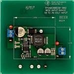
User's Guide SLVU174B–August2006–RevisedAPRIL2009 Using the TPS40200 The TPS40200EVM-002 evaluation module (EVM) uses the TPS40200 non-synchronous buck converter to provide a resistor-selected, 3.3-V output that delivers up to 2.5 A from a 24-V input bus. The EVM operates from a single supply and uses a single P-channel power FET and Schottky diode to produce a low-cost buck converter. The part operates at a 200-kHz clock frequency as determined by an external resistorandcapacitor. Contents 1 Description.................................................................................................................... 2 2 TPS40200EVM-002ElectricalandPerformanceSpecifications....................................................... 2 3 Schematic..................................................................................................................... 3 4 TestSetup.................................................................................................................... 4 5 TPS40200EVMTypicalPerformanceDataandCharacteristicCurves............................................... 7 6 EVMAssemblyDrawingsandLayout..................................................................................... 7 7 ListofMaterials............................................................................................................. 12 ListofFigures 1 TPS40200EVM-002Schematic............................................................................................ 3 2 TPS40200EVM-002RecommendedTestSetup........................................................................ 6 3 OutputRippleMeasurement-TipandBarrelUsingTP14andTP15................................................ 6 4 TPS40200EVM-002Efficiency............................................................................................. 7 5 TypicalTPS40200EVM-002LineandLoadRegulation–V =3.312V........................................... 7 OUT 6 TPS40200EVM-002ComponentPlacement(ViewedfromTop)...................................................... 8 7 TPS40200EVM-002Silkscreen(ViewedfromTop)..................................................................... 9 8 TPS40200EVM-002TopView............................................................................................ 10 9 TPS40200EVM-002BottomView........................................................................................ 11 ListofTables 1 AdjustingV WithR9RoundedtoStandard1%ResistorValues.................................................. 4 OUT 2 TPS40200EVM-002BillofMaterials..................................................................................... 12 SLVU174B–August2006–RevisedAPRIL2009 UsingtheTPS40200 1 SubmitDocumentationFeedback
Description www.ti.com 1 Description TheTPS40200EVM-002isdesignedtooperatewithan18to36-voltinputtoproducearegulated3.3-V outputwithaloadcurrentfrom0.125to2.5A.TheTPS40200EVM-002demonstratestheuseofthe TPS40200inatypicalbuckconverterapplication.Theboardsacrificessomelayoutdensitytoprovide ampletestpointsfordeviceevaluation.ThisEVMcanbemodifiedtosupportoutputvoltagesfrom0.7V to5Vandabovebychangingasinglefeedbackresistor.Table1givesspecific1%resistorvaluesfor somecommonoutputvoltages. 1.1 Features • 18-Vto36-Vinputrange • 3.3-Voutput,adjustablewithsinglefeedbackresistor • 0.125-Ato2.5-Asteady-stateoutputcurrent • 200-kHzswitchingfrequency • SingleP-channelMOSFETandsinglerectifier • Two-layer,1.275-inch· 1.675-inch,surface-mountdesignwithallcomponentsononeside • Convenienttestpointsforprobingcriticalwaveformsandnoninvasiveloopresponsetesting 1.2 Applications • Non-isolatedmedium-current,point-of-loadandlow-voltagebusconverters • Scanners • Industrialcontrols • Distributedpowersystems • DSL/cablemodems 2 TPS40200EVM-002 Electrical and Performance Specifications PARAMETER TEXTCONDITIONS MIN NOM MAX UNIT V Inputvoltage 18 24 36 V IN V Outputvoltage V =24V,I =2.5A 3.2 3.3 3.4(1) V OUT IN OUT I Outputcurrent 0.125 2.5 A OUT Lineregulation V =18-36V.I =0.125-2.5A.SetPoint 3 6 mV IN OUT VoltagemV Loadregulation V =18-36V.I =0.125-2.5A.SetPoint 3 6 mV IN OUT VoltagemV V Outputripplevoltage V =36V,I =2.5A 60 mV RIPPLE IN OUT V Outputovershoot For2.5to0.125-Aloadtransient 100 mV OVER V Outputundershoot For0.125to2.5-Aloadtransient 100 mV UNDER I Short-circuitcurrenttrippoint I +50%minimum 3.75 5 A SCP MAX Efficiency Atnominalinputvoltageandmaximumoutput 80 % current F Switchingfrequency 200 kHz S (1) Set-pointaccuracydependsonexternalresistortolerance.1%resistorsareusedinthisEVM. 2 UsingtheTPS40200 SLVU174B–August2006–RevisedAPRIL2009 SubmitDocumentationFeedback
www.ti.com Schematic 3 Schematic + + + NOTE: Forreferenceonly;seeTable2,BillofMaterialsforspecificvalues Figure1.TPS40200EVM-002Schematic SLVU174B–August2006–RevisedAPRIL2009 UsingtheTPS40200 3 SubmitDocumentationFeedback
TestSetup www.ti.com 3.1 Adjusting Output Voltage (R7 and R9) Theregulatedoutputvoltagecanbeadjustedwithinalimitedrangebychangingthegroundresistorinthe feedbackresistordivider(R7andR9).Thevalueforthefeedbackresistor(R9)foranyoutputvoltageis givenbyEquation1 V ·R7 R9 = REF V -V OUT REF (1) where • V =0.700V REF • R7=100kW Table1containscommonvaluesforR9togeneratepopularoutputvoltages.TPS40200EVM-002isstable throughthisentirerangeofoutputvoltages.Efficiencyriseswithoutputvoltage. Table1.AdjustingV WithR9Roundedto OUT Standard1%ResistorValues R9-FEEDBACKRESISTOR OUTPUTVOLTAGE(V) DIVIDER(kW ) 5 16.2 3.3 26.7 2.5 39 2 53.6 1.8 63.4 1.5 86.6 1.2 140 4 Test Setup 4.1 Equipment 4.1.1 VoltageSource V —Theinputvoltagesource(V )shouldbea0-Vto36-Vvariabledcsourcecapableofdelivering5A. IN IN METERS A1:0-Ato5-Adcammeter V1:V ,0-Vto40-Vvoltmeter IN V2:V 0Vto10-Vvoltmeter OUT 4.1.2 Loads LOAD1—Theoutputload(LOAD1)shouldbeanelectronicconstant-current-modeloadcapableof0-5A dcat1.5V. 4.1.3 RecommendedWireGauge V toJ1—Theconnectionbetweenthesourcevoltage,V andJ1oftheHPA154cancarryasmuchas IN IN 3Adc.TheminimumrecommendedwiresizeisAWG#16withthelengthofwirelessthan4feet(2feet input,2feetreturn). J2toLOAD1(Power)—ThepowerconnectionbetweenJ3oftheHPA154andLOAD1cancarryas muchas5Adc.Theminimumrecommendedwiresizeis2xAWG#16,withthelengthofwirelessthan4 feet(2feetoutput,2feetreturn). 4 UsingtheTPS40200 SLVU174B–August2006–RevisedAPRIL2009 SubmitDocumentationFeedback
www.ti.com TestSetup J2toLOAD1(RemoteSense)—Ifremotesenseisused,theremotesenseconnectionbetweenJ2of HPA154andLOAD1willcarrylessthan1Adc.TheminimumrecommendedwiresizeisAWG#22,with thelengthofwirelessand4feet(2feetoutput,2feetreturn). 4.1.4 Oscilloscope A60-MHzorfasteroscilloscopecanbeusedtomeasuretheripplevoltageonV .Theoscilloscope OUT shouldbesetfor1-MW impedance,accoupling,1-m s/divisionhorizontalresolution,and20-mV/division verticalresolutionformeasuringoutputripple.TP5andTP7canbeusedtomeasuretheoutputripple voltagebyplacingtheoscilloscopeprobetipthroughTP5andholdingthegroundbarreltoTP7asshown inFigure2.Forahands-freeapproach,theloopinTP7canbecutandopenedtocradletheprobebarrel. Usingaleadedgroundconnectionmayinduceadditionalnoiseduetothelargegroundlooparea. 4.2 Equipment Setup TherecommendedbasictestsetuptoevaluatetheTPS40200EVM-002isshowninFigure2.Notethat althoughthereturnforJ1andJ2arethesame,theconnectionsshouldremainseparateasshownin Figure2. 4.2.1 Procedure 1. WorkingatanESDworkstation,ensurethatanywriststraps,bootstraps,ormatsareconnectedto earthgroundbeforepowerisappliedtotheEVM.Electrostaticsmockandsafetyglassesshouldalso beworn. 2. Priortoconnectingthedc-inputsource,V ,itisadvisabletolimitthesourcecurrentfromV toa IN IN maximumof5A.EnsurethatV isinitiallysetto0VandconnectedasshowninFigure2. IN 3. ConnecttheammeterA1(0-Ato5-Arange)betweenV andJ1asshowninFigure2. IN 4. ConnectvoltmeterV1toTP1andTP2asshowninFigure2. 5. ConnectLOAD1toJ2asshowninFigure1.SetLOAD1toconstant-currentmodetosink0Adc beforeV isapplied. IN 6. Connectvoltmeter,V2acrossJ2pin3andJ2pin2asshowninFigure2. 7. ConnecttheoscilloscopeprobetoTP5andTP7asshowninFigure3. SLVU174B–August2006–RevisedAPRIL2009 UsingtheTPS40200 5 SubmitDocumentationFeedback
TestSetup www.ti.com 4.2.2 Diagram - + V1 Oscilloscope V 1MW,AC 18-36V_IN 10mV / div - + 20MHz - + A1 SeeTip and Barrel Measurement for Vout ripple + + + LOAD1 3.3V @ V2 - 2.5A - - Figure2.TPS40200EVM-002RecommendedTestSetup Metal Ground Barrel ProbeTip TP5 TP7 Tip and Barrel Vout ripple measurement Figure3.OutputRippleMeasurement-TipandBarrelUsingTP14andTP15 4.3 Startup/Shutdown Procedure a. IncreaseV (V1)from0Vto18Vdc. IN b. VaryLOAD1from0Ato2.5Adc. c. VaryV (V1)from18Vdcto36Vdc. IN d. DecreaseLOAD1to0A. e. DecreaseVINto0V. 4.4 Equipment Shutdown a. Shutdownoscilloscope. b. ShutdownLOAD1. c. ShutdownV . IN 6 UsingtheTPS40200 SLVU174B–August2006–RevisedAPRIL2009 SubmitDocumentationFeedback
www.ti.com TPS40200EVMTypicalPerformanceDataandCharacteristicCurves 5 TPS40200EVM Typical Performance Data and Characteristic Curves Figure4throughFigure5presenttypicalperformancecurvesfortheTPS40200EVM-002.Becauseactual performancedatacanbeaffectedbymeasurementtechniquesandenvironmentalvariables,thesecurves arepresentedforreferenceandmaydifferfromactualfieldmeasurements. 100 3.320 18 V 80 24 V V 3.315 36 V − e % g ency - 60 ut Volta 3.310 Effici 40 Outp − UT 3.305 20 VO 0 3.300 0.0 0.50 1.0 1.5 2.0 2.5 3.0 0 0.5 1 1.5 2 2.5 3 IOUT- Load Current -A IOUT−Load Current−A NOTE: V =18V,24V,and36V,V NOTE: Datatakenat18and36volts IN OUT =3.3V,I =0.125Ato2.5A withastraight-lineapproximation OUT Figure4.TPS40200EVM-002Efficiency provided. Figure5.TypicalTPS40200EVM-002Lineand LoadRegulation–V =3.312V OUT 6 EVM Assembly Drawings and Layout Thefollowingfigures(Figure6throughFigure9)showthedesignoftheTPS40200EVM-002 printed-circuitboard.TheEVMhasbeendesignedusinga2-layer,2-ozcopper-cladcircuitboard, 1.275-inch· 1.815-inchinsize,withallcomponentsonthetopsidetoallowtheusertoeasilyview,probe, andevaluatetheTPS40200controlICinapracticalapplication.Movingcomponentstobothsidesofthe PCBorusingadditionalinternallayerscanofferadditionalsizereductionforspace-constrainedsystems. SLVU174B–August2006–RevisedAPRIL2009 UsingtheTPS40200 7 SubmitDocumentationFeedback
EVMAssemblyDrawingsandLayout www.ti.com Figure6.TPS40200EVM-002ComponentPlacement(ViewedfromTop) 8 UsingtheTPS40200 SLVU174B–August2006–RevisedAPRIL2009 SubmitDocumentationFeedback
www.ti.com EVMAssemblyDrawingsandLayout Figure7.TPS40200EVM-002Silkscreen(ViewedfromTop) SLVU174B–August2006–RevisedAPRIL2009 UsingtheTPS40200 9 SubmitDocumentationFeedback
EVMAssemblyDrawingsandLayout www.ti.com Figure8.TPS40200EVM-002TopView 10 UsingtheTPS40200 SLVU174B–August2006–RevisedAPRIL2009 SubmitDocumentationFeedback
www.ti.com EVMAssemblyDrawingsandLayout Figure9.TPS40200EVM-002BottomView SLVU174B–August2006–RevisedAPRIL2009 UsingtheTPS40200 11 SubmitDocumentationFeedback
ListofMaterials www.ti.com 7 List of Materials Table2liststheEVMcomponentsasconfiguredaccordingtotheschematicshowninFigure1. Table2.TPS40200EVM-002BillofMaterials Count Ref Value Description Size PartNumber MFR Des 1 C1 100m F Capacitor,Aluminum,63V,20% 0.457x0.406 EEVFK1J101P Panasonic 2 C11, 10m F Capacitor,Ceramic,6.3V,X5R20% 0805 Std Std C12 1 C14 0.47m F Capacitor,Ceramic,16V,X5R,20% 0603 Std Std 1 C2 68pF Capacitor,Ceramic,50V,X7R,20% 0603 Std Std 2 C3,C4 0.22m F Capacitor,Ceramic,50V,X7R,20% 0805 Std Std 2 C5, 470pF Capacitor,Ceramic,50V,X7R,20% 0603 Std Std C13 1 C6 4700pF Capacitor,Ceramic,50V,X7R,20% 0603 Std Std 1 C7 33pF Capacitor,Ceramic,50V,X7R,20% 0603 Std Std 1 C8 0.1m F Capacitor,Ceramic,50V,X7R,20% 0603 Std Std 2 C9, 220m F Capacitor,Aluminum,6.3V,20% 0.260x0.276inch EEVFK0J221P Panasonic C10 1 D1 MBRS360 Diode,Schottky,3A,60V SMC MBRS360 OnSemi 1 L2 33m H Inductor,SMT,33m H,3.23A,0.06W 0.492sq" DR127-330 Coiltronics 1 Q1 FDC5614P Transistor,MOSFET,Pch,–3A,–60V, SuperSOT-6 FDC5614P Fairchild 3 R1, 100kW Resistor,Chip,1/16W,1% 0603 Std Std R5,R7 1 R10 1MW Resistor,Chip,1/16W,1% 0603 Std Std 1 R2 0.03W Resistor,Chip,W,5% 2010 Std Std 1 R3 1.0kW Resistor,Chip,1/16W,1% 0603 Std Std 1 R4 0W Resistor,Chip,1/16W,1% 0603 Std Std 1 R6 25.5W Resistor,Chip,1/16W,1% 0603 Std Std 1 R8 49.9W Resistor,Chip,1/16W,1% 0603 Std Std 1 R9 26.7kW Resistor,Chip,1/16W,1% 0603 Std Std 1 U1 TPS40200D IC,LowCostSyncBuckController SO-8 TPS40200D TI 1 – PCB,3Inx3Inx0.063In HPA154_PCB Any 12 UsingtheTPS40200 SLVU174B–August2006–RevisedAPRIL2009 SubmitDocumentationFeedback
EVALUATIONBOARD/KITIMPORTANTNOTICE TexasInstruments(TI)providestheenclosedproduct(s)underthefollowingconditions: Thisevaluationboard/kitisintendedforuseforENGINEERINGDEVELOPMENT,DEMONSTRATION,OREVALUATIONPURPOSES ONLYandisnotconsideredbyTItobeafinishedend-productfitforgeneralconsumeruse.Personshandlingtheproduct(s)musthave electronicstrainingandobservegoodengineeringpracticestandards.Assuch,thegoodsbeingprovidedarenotintendedtobecomplete intermsofrequireddesign-,marketing-,and/ormanufacturing-relatedprotectiveconsiderations,includingproductsafetyandenvironmental measurestypicallyfoundinendproductsthatincorporatesuchsemiconductorcomponentsorcircuitboards.Thisevaluationboard/kitdoes notfallwithinthescopeoftheEuropeanUniondirectivesregardingelectromagneticcompatibility,restrictedsubstances(RoHS),recycling (WEEE),FCC,CEorUL,andthereforemaynotmeetthetechnicalrequirementsofthesedirectivesorotherrelateddirectives. Shouldthisevaluationboard/kitnotmeetthespecificationsindicatedintheUser’sGuide,theboard/kitmaybereturnedwithin30daysfrom thedateofdeliveryforafullrefund.THEFOREGOINGWARRANTYISTHEEXCLUSIVEWARRANTYMADEBYSELLERTOBUYER ANDISINLIEUOFALLOTHERWARRANTIES,EXPRESSED,IMPLIED,ORSTATUTORY,INCLUDINGANYWARRANTYOF MERCHANTABILITYORFITNESSFORANYPARTICULARPURPOSE. Theuserassumesallresponsibilityandliabilityforproperandsafehandlingofthegoods.Further,theuserindemnifiesTIfromallclaims arisingfromthehandlingoruseofthegoods.Duetotheopenconstructionoftheproduct,itistheuser’sresponsibilitytotakeanyandall appropriateprecautionswithregardtoelectrostaticdischarge. EXCEPTTOTHEEXTENTOFTHEINDEMNITYSETFORTHABOVE,NEITHERPARTYSHALLBELIABLETOTHEOTHERFORANY INDIRECT,SPECIAL,INCIDENTAL,ORCONSEQUENTIALDAMAGES. TIcurrentlydealswithavarietyofcustomersforproducts,andthereforeourarrangementwiththeuserisnotexclusive. TIassumesnoliabilityforapplicationsassistance,customerproductdesign,softwareperformance,orinfringementofpatentsor servicesdescribedherein. PleasereadtheUser’sGuideand,specifically,theWarningsandRestrictionsnoticeintheUser’sGuidepriortohandlingtheproduct.This noticecontainsimportantsafetyinformationabouttemperaturesandvoltages.ForadditionalinformationonTI’senvironmentaland/or safetyprograms,pleasecontacttheTIapplicationengineerorvisitwww.ti.com/esh. NolicenseisgrantedunderanypatentrightorotherintellectualpropertyrightofTIcoveringorrelatingtoanymachine,process,or combinationinwhichsuchTIproductsorservicesmightbeorareused. FCCWarning Thisevaluationboard/kitisintendedforuseforENGINEERINGDEVELOPMENT,DEMONSTRATION,OREVALUATIONPURPOSES ONLYandisnotconsideredbyTItobeafinishedend-productfitforgeneralconsumeruse.Itgenerates,uses,andcanradiateradio frequencyenergyandhasnotbeentestedforcompliancewiththelimitsofcomputingdevicespursuanttopart15ofFCCrules,whichare designedtoprovidereasonableprotectionagainstradiofrequencyinterference.Operationofthisequipmentinotherenvironmentsmay causeinterferencewithradiocommunications,inwhichcasetheuserathisownexpensewillberequiredtotakewhatevermeasuresmay berequiredtocorrectthisinterference. EVMWARNINGSANDRESTRICTIONS ItisimportanttooperatethisEVMwithintheinputvoltagerangeof0Vto36Vandtheoutputvoltagerangeof0Vto6.3V. Exceedingthespecifiedinputrangemaycauseunexpectedoperationand/orirreversibledamagetotheEVM.Iftherearequestions concerningtheinputrange,pleasecontactaTIfieldrepresentativepriortoconnectingtheinputpower. Applyingloadsoutsideofthespecifiedoutputrangemayresultinunintendedoperationand/orpossiblepermanentdamagetotheEVM. PleaseconsulttheEVMUser'sGuidepriortoconnectinganyloadtotheEVMoutput.Ifthereisuncertaintyastotheloadspecification, pleasecontactaTIfieldrepresentative. Duringnormaloperation,somecircuitcomponentsmayhavecasetemperaturesgreaterthan100(cid:176) C.TheEVMisdesignedtooperate properlywithcertaincomponentsabove100(cid:176) Caslongastheinputandoutputrangesaremaintained.Thesecomponentsincludebutare notlimitedtolinearregulators,switchingtransistors,passtransistors,andcurrentsenseresistors.Thesetypesofdevicescanbeidentified usingtheEVMschematiclocatedintheEVMUser'sGuide.Whenplacingmeasurementprobesnearthesedevicesduringoperation, pleasebeawarethatthesedevicesmaybeverywarmtothetouch. MailingAddress:TexasInstruments,PostOfficeBox655303,Dallas,Texas75265 Copyright2006,TexasInstrumentsIncorporated
IMPORTANTNOTICE TexasInstrumentsIncorporatedanditssubsidiaries(TI)reservetherighttomakecorrections,modifications,enhancements,improvements, andotherchangestoitsproductsandservicesatanytimeandtodiscontinueanyproductorservicewithoutnotice.Customersshould obtainthelatestrelevantinformationbeforeplacingordersandshouldverifythatsuchinformationiscurrentandcomplete.Allproductsare soldsubjecttoTI’stermsandconditionsofsalesuppliedatthetimeoforderacknowledgment. TIwarrantsperformanceofitshardwareproductstothespecificationsapplicableatthetimeofsaleinaccordancewithTI’sstandard warranty.TestingandotherqualitycontroltechniquesareusedtotheextentTIdeemsnecessarytosupportthiswarranty.Exceptwhere mandatedbygovernmentrequirements,testingofallparametersofeachproductisnotnecessarilyperformed. TIassumesnoliabilityforapplicationsassistanceorcustomerproductdesign.Customersareresponsiblefortheirproductsand applicationsusingTIcomponents.Tominimizetherisksassociatedwithcustomerproductsandapplications,customersshouldprovide adequatedesignandoperatingsafeguards. TIdoesnotwarrantorrepresentthatanylicense,eitherexpressorimplied,isgrantedunderanyTIpatentright,copyright,maskworkright, orotherTIintellectualpropertyrightrelatingtoanycombination,machine,orprocessinwhichTIproductsorservicesareused.Information publishedbyTIregardingthird-partyproductsorservicesdoesnotconstitutealicensefromTItousesuchproductsorservicesora warrantyorendorsementthereof.Useofsuchinformationmayrequirealicensefromathirdpartyunderthepatentsorotherintellectual propertyofthethirdparty,oralicensefromTIunderthepatentsorotherintellectualpropertyofTI. ReproductionofTIinformationinTIdatabooksordatasheetsispermissibleonlyifreproductioniswithoutalterationandisaccompanied byallassociatedwarranties,conditions,limitations,andnotices.Reproductionofthisinformationwithalterationisanunfairanddeceptive businesspractice.TIisnotresponsibleorliableforsuchaltereddocumentation.Informationofthirdpartiesmaybesubjecttoadditional restrictions. ResaleofTIproductsorserviceswithstatementsdifferentfromorbeyondtheparametersstatedbyTIforthatproductorservicevoidsall expressandanyimpliedwarrantiesfortheassociatedTIproductorserviceandisanunfairanddeceptivebusinesspractice.TIisnot responsibleorliableforanysuchstatements. TIproductsarenotauthorizedforuseinsafety-criticalapplications(suchaslifesupport)whereafailureoftheTIproductwouldreasonably beexpectedtocauseseverepersonalinjuryordeath,unlessofficersofthepartieshaveexecutedanagreementspecificallygoverning suchuse.Buyersrepresentthattheyhaveallnecessaryexpertiseinthesafetyandregulatoryramificationsoftheirapplications,and acknowledgeandagreethattheyaresolelyresponsibleforalllegal,regulatoryandsafety-relatedrequirementsconcerningtheirproducts andanyuseofTIproductsinsuchsafety-criticalapplications,notwithstandinganyapplications-relatedinformationorsupportthatmaybe providedbyTI.Further,BuyersmustfullyindemnifyTIanditsrepresentativesagainstanydamagesarisingoutoftheuseofTIproductsin suchsafety-criticalapplications. TIproductsareneitherdesignednorintendedforuseinmilitary/aerospaceapplicationsorenvironmentsunlesstheTIproductsare specificallydesignatedbyTIasmilitary-gradeor"enhancedplastic."OnlyproductsdesignatedbyTIasmilitary-grademeetmilitary specifications.BuyersacknowledgeandagreethatanysuchuseofTIproductswhichTIhasnotdesignatedasmilitary-gradeissolelyat theBuyer'srisk,andthattheyaresolelyresponsibleforcompliancewithalllegalandregulatoryrequirementsinconnectionwithsuchuse. TIproductsareneitherdesignednorintendedforuseinautomotiveapplicationsorenvironmentsunlessthespecificTIproductsare designatedbyTIascompliantwithISO/TS16949requirements.Buyersacknowledgeandagreethat,iftheyuseanynon-designated productsinautomotiveapplications,TIwillnotberesponsibleforanyfailuretomeetsuchrequirements. FollowingareURLswhereyoucanobtaininformationonotherTexasInstrumentsproductsandapplicationsolutions: Products Applications Amplifiers amplifier.ti.com Audio www.ti.com/audio DataConverters dataconverter.ti.com Automotive www.ti.com/automotive DLP®Products www.dlp.com Broadband www.ti.com/broadband DSP dsp.ti.com DigitalControl www.ti.com/digitalcontrol ClocksandTimers www.ti.com/clocks Medical www.ti.com/medical Interface interface.ti.com Military www.ti.com/military Logic logic.ti.com OpticalNetworking www.ti.com/opticalnetwork PowerMgmt power.ti.com Security www.ti.com/security Microcontrollers microcontroller.ti.com Telephony www.ti.com/telephony RFID www.ti-rfid.com Video&Imaging www.ti.com/video RF/IFandZigBee®Solutions www.ti.com/lprf Wireless www.ti.com/wireless MailingAddress:TexasInstruments,PostOfficeBox655303,Dallas,Texas75265 Copyright©2009,TexasInstrumentsIncorporated