ICGOO在线商城 > 集成电路(IC) > PMIC - 热插拔控制器 > TPS24700DGKR
 Datasheet下载
- 型号: TPS24700DGKR
- 制造商: Texas Instruments
- 库位|库存: xxxx|xxxx
- 要求:
| 数量阶梯 | 香港交货 | 国内含税 |
| +xxxx | $xxxx | ¥xxxx |
查看当月历史价格
查看今年历史价格
TPS24700DGKR产品简介:
ICGOO电子元器件商城为您提供TPS24700DGKR由Texas Instruments设计生产,在icgoo商城现货销售,并且可以通过原厂、代理商等渠道进行代购。 TPS24700DGKR价格参考¥7.25-¥14.72。Texas InstrumentsTPS24700DGKR封装/规格:PMIC - 热插拔控制器, Hot Swap Controller 1 Channel General Purpose 8-VSSOP。您可以下载TPS24700DGKR参考资料、Datasheet数据手册功能说明书,资料中有TPS24700DGKR 详细功能的应用电路图电压和使用方法及教程。
| 参数 | 数值 |
| 产品目录 | 集成电路 (IC) |
| 描述 | IC CTRLR HOT SWAP 2.5-18V 8VSSOP |
| 产品分类 | |
| 品牌 | Texas Instruments |
| 数据手册 | |
| 产品图片 |
|
| 产品型号 | TPS24700DGKR |
| PCN设计/规格 | |
| rohs | 无铅 / 符合限制有害物质指令(RoHS)规范要求 |
| 产品系列 | - |
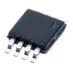
| 供应商器件封装 | 8-VSSOP |
| 其它名称 | 296-28560-6 |
| 内部开关 | 无 |
| 功能引脚 | EN, PGB, TIMER |
| 包装 | Digi-Reel® |
| 可编程特性 | 限流,故障超时,UVLO |
| 安装类型 | 表面贴装 |
| 封装/外壳 | 8-TSSOP,8-MSOP(0.118",3.00mm 宽) |
| 工作温度 | -40°C ~ 85°C |
| 应用 | 通用 |
| 标准包装 | 1 |
| 特性 | 闭锁故障,发热限制 |
| 特色产品 | http://www.digikey.com/cn/zh/ph/Texas-Instruments/tps24700-mosfet.html |
| 电压-电源 | 2.5 V ~ 18 V |
| 电流-电源 | 1mA |
| 电流-输出(最大值) | - |
| 类型 | 热交换控制器 |
| 通道数 | 1 |
| 配用 | /product-detail/zh/TPS24700EVM-001/296-28536-ND/2642727 |


- 商务部:美国ITC正式对集成电路等产品启动337调查
- 曝三星4nm工艺存在良率问题 高通将骁龙8 Gen1或转产台积电
- 太阳诱电将投资9.5亿元在常州建新厂生产MLCC 预计2023年完工
- 英特尔发布欧洲新工厂建设计划 深化IDM 2.0 战略
- 台积电先进制程称霸业界 有大客户加持明年业绩稳了
- 达到5530亿美元!SIA预计今年全球半导体销售额将创下新高
- 英特尔拟将自动驾驶子公司Mobileye上市 估值或超500亿美元
- 三星加码芯片和SET,合并消费电子和移动部门,撤换高东真等 CEO
- 三星电子宣布重大人事变动 还合并消费电子和移动部门
- 海关总署:前11个月进口集成电路产品价值2.52万亿元 增长14.8%


PDF Datasheet 数据手册内容提取
TPS24700 TPS24701 www.ti.com SLVSAL3B–MARCH2011–REVISEDMAY2011 2.5-V to 18-V High-Efficiency Hot-Swap Controller CheckforSamples:TPS24700,TPS24701 FEATURES APPLICATIONS 1 • 2.5-Vto18-VOperation • ServerBackplanes • AccurateCurrentLimitingforStarup • StorageAreaNetworks(SAN) • Accurate25-mVCurrentSenseThreshold • MedicalSystems • TimedOvercurrentBreaker • Plug-InModules • Power-GoodOutput • BaseStations • FastBreakerforShort-CircuitProtection • ConsumerElectronics • LatchOff(TPS24700)andRetryVersions (TPS24701) • ProgrammableUVThreshold • Drop-InUpgradeforLTC4211–NoLayout Changes • SmallMSOP-8Package DESCRIPTION The TPS24700/1 is an easy-to-use, 2.5 V to 18 V, hot-swap controller that drives an external N-channel MOSFET. The programmable current limit and fault time protect the supply and load from excessive current at startup. After startup, currents above the user-selected limit are allowed to flow until programmed timeout – except in extreme overload events when load is immediately disconnected from source. The low, 25-mV current sense threshold is highly accurate and allows use of smaller, more-efficient sense resistors, yielding lower power lossandsmallerfootprint.Apower-goodoutputisprovidedforstatusmonitoringanddownstreamloadcontrol. TPS24700/1 replaces the LTC4211 in existing designs with no PCB board changes and only minor external componentchanges– yieldingamoreaccurate,efficientsolution. TextforSpacing TextforSpacing TYPICALAPPLICATIONOFTPS24700/1(12VAT10A) PINOUT RSENSE M1 DGK Package VIN 2 mΩ CSD16403Q5 VOUT (Top View) C OUT PGb 1 8 VCC C 470μF 1 0.1μF EN 2 7 SENSE RGATE TIMER 3 6 GATE 10Ω GND 4 5 OUT 3V R 1 130 kΩ VCC SENSE GATE OUT R 4 EN 3.01 kΩ R2 TPS2470x PGb 18.7kΩ TIMER GND C T V = 10.8 V 56 nF UVLO I = 12A LMT t = 7.56 ms FAULT 1 Pleasebeawarethatanimportantnoticeconcerningavailability,standardwarranty,anduseincriticalapplicationsofTexas Instrumentssemiconductorproductsanddisclaimerstheretoappearsattheendofthisdatasheet. PRODUCTIONDATAinformationiscurrentasofpublicationdate. Copyright©2011,TexasInstrumentsIncorporated Products conform to specifications per the terms of the Texas Instruments standard warranty. Production processing does not necessarilyincludetestingofallparameters.
TPS24700 TPS24701 SLVSAL3B–MARCH2011–REVISEDMAY2011 www.ti.com This integrated circuit can be damaged by ESD. Texas Instruments recommends that all integrated circuits be handled with appropriateprecautions.Failuretoobserveproperhandlingandinstallationprocedurescancausedamage. ESDdamagecanrangefromsubtleperformancedegradationtocompletedevicefailure.Precisionintegratedcircuitsmaybemore susceptibletodamagebecauseverysmallparametricchangescouldcausethedevicenottomeetitspublishedspecifications. DEVICEINFORMATION T PACKAGE PARTNUMBER(1) FUNCTION MARKING A TPS24700 Latched 24700 –40ºCto85ºC MSOP-8 TPS24701 Retry 24701 (1) Forthemostcurrentpackageandorderinginformation,seethePackageOptionAddendumattheendofthisdocument,orseetheTI Websiteatwww.ti.com. ABSOLUTE MAXIMUM RATINGS overoperatingfree-airtemperaturerange,allvoltagesreferredtoGND(unlessotherwisenoted) VALUE UNIT EN,GATE,OUT,PGb(1),SENSE,VCC –0.3to30 Inputvoltagerange SENSEtoVCC –0.3to0.3 V TIMER –0.3to5 Sinkcurrent PGb 5 mA AllpinsexceptPGb 2 Human-bodymodel ESDrating PGb 0.5 kV Charged-devicemodel 0.5 Temperature Maximumjunction,T Internallylimited °C J (1) Donotapplyvoltagesdirectlytothesepins. THERMAL INFORMATION TPS24700/01 THERMALMETRIC(1) UNIT MSOP(8)PINS θ Junction-to-ambientthermalresistance 57.2 °C/W JA θ Junction-to-case(top)thermalresistance 110.5 °C/W JCtop θ Junction-to-boardthermalresistance 60.7 °C/W JB ψ Junction-to-topcharacterizationparameter 7.8 °C/W JT ψ Junction-to-boardcharacterizationparameter 24 °C/W JB θ Junction-to-case(bottom)thermalresistance 14.3 °C/W JCbot (1) Formoreinformationabouttraditionalandnewthermalmetrics,seetheICPackageThermalMetricsapplicationreport,SPRA953. 2 SubmitDocumentationFeedback Copyright©2011,TexasInstrumentsIncorporated ProductFolderLink(s):TPS24700TPS24701
TPS24700 TPS24701 www.ti.com SLVSAL3B–MARCH2011–REVISEDMAY2011 RECOMMENDED OPERATING CONDITIONS overoperatingfree-airtemperaturerange(unlessotherwisenoted) MIN NOM MAX UNIT SENSE,VCC 2.5 18 Inputvoltagerange V EN,PGb,OUT 0 18 Sinkcurrent PGb 0 2 mA TIMER 1 nF Externalcapacitance GATE(1) 1 µF Operatingjunctiontemperaturerange,T –40 125 °C J (1) ExternalcapacitancetiedtoGATEshouldbeinserieswitharesistornolessthan1kΩ. ELECTRICAL CHARACTERISTICS –40°C≤T ≤125°C,V =12V,andV =3V. J CC EN AllvoltagesreferencedtoGND,unlessotherwisenoted. PARAMETER CONDITIONS MIN NOM MAX UNIT VCC UVLOthreshold,rising 2.2 2.32 2.45 V UVLOthreshold,falling 2.1 2.22 2.35 V UVLOhysteresis(1) 0.1 V Enabled―I +I +I 1 1.4 mA OUT VCC SENSE Supplycurrent Disabled―EN=0V,I +I +I 0.45 mA OUT VCC SENSE EN Thresholdvoltage,falling 1.2 1.3 1.4 V Hysteresis(1) 50 mV Inputleakagecurrent 0V≤V ≤30V –1 0 1 µA EN Turnofftime EN↓toV <1V,C =33nF 20 60 150 µs GATE GATE Deglitchtime EN↑ 8 14 18 µs Disabledelay EN↓toGATE↓,C =0,t ,SeeFigure1 0.1 0.4 1 µs GATE pff50–90 PGb Threshold V rising,PGbgoinghigh 140 240 340 (SENSE–OUT) mV Hysteresis(1) MeasuredV falling,PGbgoinglow 70 (SENSE–OUT) Outputlowvoltage Sinking2mA 0.11 0.25 V Inputleakagecurrent V =0V,30V –1 0 1 µA PGb Delay(deglitch)time Risingorfallingedge 2 3.4 6 ms TIMER Sourcingcurrent V =0V 8 10 12 µA TIMER V =2V 8 10 12 µA TIMER Sinkingcurrent V =0V,V =2V 2 4.5 7 mA EN TIMER Upperthresholdvoltage 1.3 1.35 1.4 V Lowerthresholdvoltage 0.33 0.35 0.37 V Timeractivationvoltage RaiseGATEuntilI sinking,measureV ,V =12V 5 5.9 7 V TIMER (GATE–VCC) CC Bleed-downresistance V =2V 70 104 130 kΩ TIMER OUT Inputbiascurrent V =12V 16 30 µA OUT GATE Outputvoltage V =12V 23.5 25.8 28 V OUT Clampvoltage Inject10µAintoGATE,measureV 12 13.9 15.5 V (GATE–VCC) Sourcingcurrent V =12V 20 30 40 µA GATE (1) TheseparametersareprovidedforreferenceonlyanddonotconstitutepartofTI’spublisheddevicespecificationsforpurposesofTI’s productwarranty. Copyright©2011,TexasInstrumentsIncorporated SubmitDocumentationFeedback 3 ProductFolderLink(s):TPS24700TPS24701
TPS24700 TPS24701 SLVSAL3B–MARCH2011–REVISEDMAY2011 www.ti.com ELECTRICAL CHARACTERISTICS (continued) –40°C≤T ≤125°C,V =12V,andV =3V. J CC EN AllvoltagesreferencedtoGND,unlessotherwisenoted. PARAMETER CONDITIONS MIN NOM MAX UNIT Fastturnoff,V =14V 0.5 1 1.4 A GATE Sinkingcurrent Sustained,V =4Vto23V 6 11 20 mA GATE Ininrushcurrentlimit,V =4V–23V 20 30 40 µA GATE Pulldownresistance Thermalshutdown 14 20 26 kΩ Turnondelay V risingtoGATEsourcing,t ,SeeFigure2 100 250 µs CC prr50-50 SENSE Inputbiascurrent V =12V,sinkingcurrent 30 40 µA SENSE Currentlimitthreshold V =12V 22.5 25 27.5 mV OUT Fast-tripthreshold 52 60 68 mV Fast-turnoffduration 8 13.5 18 µs Fast-turnoffdelay V =80mV,C =0pF,t ,SeeFigure3 200 ns (VCC–VSENSE) GATE prf50–50 OTSD Threshold,rising 130 140 °C Hysteresis(1) 10 °C VGATE 90% IGATE 50% VEN VVCC 50% 50% 0 Time 0 Time t(pff50-90) t(prr50-50) T0492-01 T0494-01 Figure1.t TimingDefinition Figure2.t TimingDefinition pff50–90 prr50–50 V GATE 50% V –V VCC SENSE 50% 0 Time t (prf50-50) T0495-01 Figure3.t TimingDefinition prf50–50 4 SubmitDocumentationFeedback Copyright©2011,TexasInstrumentsIncorporated ProductFolderLink(s):TPS24700TPS24701
TPS24700 TPS24701 www.ti.com SLVSAL3B–MARCH2011–REVISEDMAY2011 FUNCTIONAL BLOCK DIAGRAM M1 VIN RSENSE RGATE SENSE GATE OUT 7 6 5 60 mV DC Charge VCC RSET + – Pump Inrush 8 ASmeprlvifoier – + Fast 30 µA + Gate SLatchQ Summing Comparator – Comparator Point 1-shot 11 mA VCC + R Q 6 V – 0~60 µA RIMON + 675 mV – Main Opamp in Inrush Limit Becomes Comparator After Inrush Limit Complete 20 kΩ 2 ms 1 PGb UVLO + + DC 22..2322 VV – 124700 mmVV – ComPpGarator EN 2 + 1.35 V – 1.3 V 14 µs 10 µA Fault Logic + POR 1.5 V – TSD 4 GND 10 µA 3 TIMER CT B0438-03 Figure4. BlockDiagramoftheTPS24700/1 PINFUNCTIONS NAME TPS24700/1 I/O DESCRIPTION EN 2 I Active-highenableinput.Logicinput.Connectstoresistordivider GATE 6 O GatedriveroutputforexternalMOSFET GND 4 – Ground OUT 5 I OutputvoltagesensorformonitoringMOSFETpower PGb 1 O Active-low,open-drainpowergoodindicator.StatusisdeterminedbythevoltageacrosstheMOSFET. SENSE 7 I CurrentsensinginputforresistorshuntfromVCCtoSENSE TIMER 3 I/O AcapacitorconnectedfromthispintoGNDprovidesafaulttimingfunction. VCC 8 I Input-voltagesenseandpowersupply Copyright©2011,TexasInstrumentsIncorporated SubmitDocumentationFeedback 5 ProductFolderLink(s):TPS24700TPS24701
TPS24700 TPS24701 SLVSAL3B–MARCH2011–REVISEDMAY2011 www.ti.com DETAILED PIN DESCRIPTIONS The following description relies on the typical application diagram shown on the front page of this data sheet, as wellasthefunctionalblockdiagramofFigure4. EN: Applying a voltage of 1.35 V or more to this pin enables the gate driver. The addition of an external resistor divider allows the EN pin to serve as an undervoltage monitor. Cycling EN low and then back high resets a TPS24700thathaslatchedoffduetoafaultcondition.Thispinshouldnotbeleftfloating. GATE: This pin provides gate drive to the external MOSFET. A charge pump sources 30 µA to enhance the external MOSFET. A 13.9-V clamp between GATE and VCC limits the gate-to-source voltage, because V is VCC very close to V in normal operation. During start-up, a transconductance amplifier regulates the gate voltage OUT of M1 to provide inrush current limiting. The TIMER pin charges timer capacitor C during the inrush. Inrush T current limiting continues until the V exceeds the Timer Activation Voltage (6 V for V = 12 V). Then (GATE–VCC) VCC the TPS24700/1 enters into circuit-breaker mode. The Timer Activation Voltage is defined as a threshold voltage. When V exceeds this threshold voltage, the inrush operation is finished and the TIMER stops sourcing (GATE-VCC) current and begins sinking current. In the circuit-breaker mode, the current flowing in R is compared with SENSE the current-limit threshold derived from Equation 1. If the current flowing in R exceeds the current limit SENSE threshold,thenMOSFETM1isturnedoff.TheGATEpinisdisabledbythefollowingthreemechanisms: 1. GATEispulleddownbyan11-mAcurrentsourcewhen – Thefaulttimerexpiresduringanoverloadcurrentfault(V > 25mV) SENSE – V isbelowitsfallingthreshold EN – V dropsbelowtheUVLOthreshold VCC 2. GATE is pulled down by a 1-A current source for 13.5 µs when a hard output short circuit occurs and V is greater than 60 mV, i.e., the fast-trip shutdown threshold. After fast-trip shutdown is complete, (VCC–SENSE) an11-mAsustainingcurrentensuresthattheexternalMOSFETremainsoff. 3. GATE is discharged by a 20-kΩ resistor to GND if the chip die temperature exceeds the OTSD rising threshold. GATEremainslowinlatchmode(TPS24700)andattemptsarestartperiodicallyinretrymode(TPS24701). If used, any capacitor connecting GATE and GND should not exceed 1 μF and it should be connected in series witharesistorofnolessthan1kΩ.NoexternalresistorshouldbedirectlyconnectedfromGATEtoGNDorfrom GATEtoOUT. GND:Thispinisconnectedtosystemground. OUT:Thispinallowsthecontrollertomeasurethedrain-to-sourcevoltageacrosstheexternalMOSFETM1.The power-good indicator (PGb) relies on this information. The OUT pin should be protected from negative voltage transients by a clamping diode or sufficient capacitors. A Schottky diode of 3 A / 40 V in an SMC package is recommended as a clamping diode for high-power applications. The OUT pin should be bypassed to GND with a low-impedanceceramiccapacitorintherangeof10nFto1μF. PGb: This active-low, open-drain output is intended to interface to downstream dc/dc converters or monitoring circuits. PGb pulls low after the drain-to-source voltage of the FET has fallen below 170 mV and a 3.4-ms deglitch delay has elapsed. It goes open-drain when VDS exceeds 240 mV. PGb assumes high-impedance status after a 3.4-ms deglitch delay once V of M1 rises up, resulting from GATE being pulled to GND at any of DS thefollowingconditions: • Anoverloadcurrentfaultoccurs(V >25mV). SENSE • A hard output short circuit occurs, leading to V greater than 60 mV, i.e., the fast-trip shutdown (VCC–SENSE) thresholdhasbeenexceeded. • V isbelowitsfallingthreshold. EN • V dropsbelowtheUVLOthreshold. VCC • DietemperatureexceedstheOTSDthreshold. SENSE: This pin connects to the negative terminal of R . It provides a means of sensing the voltage across SENSE this resistor, as well as a way to monitor the drain-to-source voltage across the external FET. The current limit I issetbyEquation1. LIM 25mV I = LIM R SENSE (1) 6 SubmitDocumentationFeedback Copyright©2011,TexasInstrumentsIncorporated ProductFolderLink(s):TPS24700TPS24701
TPS24700 TPS24701 www.ti.com SLVSAL3B–MARCH2011–REVISEDMAY2011 Afast-tripshutdownoccurswhenV exceeds60mV. (VCC–VSENSE) TIMER: A capacitor C connected from the TIMER pin to GND determines the overload fault timing. TIMER T sources10μAwhenanoverloadispresent,anddischargesC at10 μAotherwise.M1isturnedoffwhenV T TIMER reaches 1.35 V. In an application implementing auto-retry after a fault, this capacitor also determines the period before the external MOSFET is re-enabled. A minimum timing capacitance of 1 nF is recommended to ensure proper operation of the fault timer. The value of C can be calculated from the desired fault time t , using T FLT Equation2. 10μA C = ´ t T FLT 1.35 V (2) The latch mode (TPS24700) or the retry mode (TPS24701) occurs if the load current exceeds the current limit threshold or the fast-trip shutdown threshold. While in latch mode, the TIMER pin continues to charge and discharge the attached capacitor periodically. In retry mode, the external MOSFET is disabled for sixteen cycles of TIMER charging and discharging. The TIMER pin is pulled to GND by a 2-mA current source at the end of the 16th cycle of charging and discharging. The external MOSFET is then re-enabled. The TIMER pin capacitor, C , T can also be discharged to GND during latch mode or retry mode by a 2-mA current source whenever any of the followingoccurs: • V isbelowitsfallingthreshold. EN • V dropsbelowtheUVLOthreshold. VCC VCC:Thispinperformsthreefunctions.First,itprovidesbiasingpowertotheintegratedcircuit.Second,itserves as an input to the power-on reset (POR) and undervoltage lockout (UVLO) functions. The VCC trace from the integrated circuit should connect directly to the positive terminal of R to minimize the voltage sensing error. SENSE Bypass capacitor C , shown in the typical application diagram on the front page, should be connected to the 1 positiveterminalofR .Acapacitanceofatleast10nFisrecommended. SENSE Copyright©2011,TexasInstrumentsIncorporated SubmitDocumentationFeedback 7 ProductFolderLink(s):TPS24700TPS24701
TPS24700 TPS24701 SLVSAL3B–MARCH2011–REVISEDMAY2011 www.ti.com TYPICAL CHARACTERISTICS 1200 5 T = 125°C 4 1000 T = 25°C A) A) µnt ( T = 125°C µnt ( 3 T = 25°C e e urr 800 urr C C ply ply 2 p p u T = –40°C u T = –40°C S S 600 1 400 0 0 2 4 6 8 10 12 14 16 18 20 0 2 4 6 8 10 12 14 16 18 20 Input Voltage, V (V) Input Voltage, V (V) VCC VCC Figure5.SupplyCurrentvsInputVoltageatNormal Figure6.SupplyCurrentvsInputVoltageatShutdown Operation(EN=High) (EN=0V) 26.5 40 Gate Current at Current Limiting 26 VVCC = 12 V 32 VVCC Voltage = 12 V oltage, V (V)–(VCC SENSE) 22452..555 VVCC = 2.5 V VVCC = 18 V µOSFET Gate Current (A) –112–664088 T = 25°C T = –40°C T = 125°C V M –24 24 –32 23.5 –40 –50 –20 10 40 70 100 130 0 5 10 15 20 25 30 35 40 45 50 55 Temperature (°C) Voltage, V(VCC – SENSE) (mV) Figure7.VoltageAcrossR inInrushCurrent Figure8.GateCurrentvsVoltageAcrossR During SENSE SENSE LimitingvsTemperature InrushCurrentLimiting 1.8 0.25 0.9 0.25 V = 12 V 1.6 T = –40°C VCC 0.2 0.7 0.2 T = –40°C T = 25°C 1.4 0.15 V) 0.6 T = 25°C 0.15 V) 1.2 0.1 ()E 0.5 0.1 ()E A) NS A) NS e Current ( 00..681 T = 125°C V(VCC – SENSE) 00–.00.505 V–(VCC SE e Current ( 000...423 T = 125°C V(VCC – SENSE) 00–.00.505 V–(VCC SE Gat 0.4 –0.1 age, Gat 0.1 –0.1 age, 0.2 –0.15 Volt 0 –0.15 Volt 0 –0.2 –0.1 V = 3.3 V –0.2 VCC –0.2 –0.25 –0.2 –0.25 –10 0 10 20 30 40 –10 0 10 20 30 40 Time (µs) Time (µs) Figure9.GateCurrentDuringFastTrip, Figure10.GateCurrentDuringFastTrip, V =V =12V V =V =3.3V VCC GATE VCC GATE 8 SubmitDocumentationFeedback Copyright©2011,TexasInstrumentsIncorporated ProductFolderLink(s):TPS24700TPS24701
TPS24700 TPS24701 www.ti.com SLVSAL3B–MARCH2011–REVISEDMAY2011 TYPICAL CHARACTERISTICS (continued) V) 32 7 D, V (GATE 28 T = 125°C T = 25°C eshold (V) 6 T = 125°C T = 25°C GN 24 Thr o e d t ag T = –40°C ce 20 olt 5 n V ere T = –40°C on Ref 16 vati ate Voltage 12 TIMER Acti 4 G 8 3 0 4 8 12 16 20 0 4 8 12 16 20 Input Voltage, V (V) Input Voltage, V (V) VCC VCC Figure11.GateVoltageWithZeroGateCurrentvsV Figure12.TIMERActivationVoltageThresholdvsV at VCC VCC VariousTemperatures 2 2.36 VVCC = 12 V VVCC = 12 V UVLO Upper Threshold EN Upper Threshold e (V) 1.6 ge (V) 2.32 g a olta 1.2 Volt old V hold 2.28 h s hres 0.8 Thre UVLO Lower Threshold EN T 0.4 UVLO 2.24 0 2.20 –50 –20 –10 10 30 50 70 90 110 130 –50 –20 10 40 70 100 130 Temperature (°C) Temperature (°C) Figure13.ENThresholdVoltagevsTemperature Figure14.UVLOThresholdVoltagesvsTemperature 240 64 V) me ( 220 PGb Rising mV) 63.5 VVCC = 12 V oltag ge ( 63 V a old 200 Volt 62.5 VVCC = 2.5 V esh old 62 Thr 180 esh UT) PGb Falling Thr 61.5 O p –ENSE 160 ast-Tri 61 VVCC = 18 V V(S F 60.5 140–50 –20 10 40 70 100 130 60–50 –20 10 40 70 100 130 Temperature (°C) Temperature (°C) Figure15.ThresholdofV vsTemperature,PGbRising Figure16.Fast-TripThresholdvsTemperature DS andFalling Copyright©2011,TexasInstrumentsIncorporated SubmitDocumentationFeedback 9 ProductFolderLink(s):TPS24700TPS24701
TPS24700 TPS24701 SLVSAL3B–MARCH2011–REVISEDMAY2011 www.ti.com TYPICAL CHARACTERISTICS (continued) V) 160 0.7 m V = 0 V e ( EN T = 125°C g a 140 0.6 olt ut V µA) utp 120 nt ( 0.5 T = 25°C ain O VVCC = 2.5 V VVCC = 18 V Curre Open-Dr 100 Supply 0.4 ate 80 0.3 T = –40°C w-St VVCC = 12 V o L 60 0.2 –50 –20 10 40 70 100 130 0 4 8 12 16 20 Temperature (°C) Input Voltage, V (V) VCC Figure17.PGbOpen-DrainOutputVoltageinLowState Figure18.SupplyCurrentvsV andTemperatureWhen VCC ENPulledLow 1.344 0.365 V) V) e ( 1.342 e ( g g Volta VVCC = 12 V VVCC = 18 V Volta 0.362 VVCC = 18 V old 1.34 old sh sh VVCC = 12 V e e hr hr per T 1.338 wer T 0.36 Up Lo er 1.336 VVCC = 2.5 V er m m Ti Ti VVCC = 2.5 V 1.334 0.357 –50 –20 10 40 70 100 130 –50 –20 10 40 70 100 130 Temperature (°C) Temperature (°C) Figure19.TimerUpperThresholdvsV and Figure20.TimerLowerThresholdvsV and VCC VCC Temperature Temperature 10.2 10.4 µurcing Current (A) 19901...9081 VVCC = 12 V VVCC = 18 V µ Current (A)nking 1110001...1203 VVCC = 12 V VVCC = 18 V mer So 9.7 VVCC = 2.5 V mer Si 9.9 VVCC = 2.5 V Ti Ti 9.6 9.8 9.5 9.7 –50 –20 10 40 70 100 130 –50 –20 10 40 70 100 130 Temperature (°C) Temperature (°C) Figure21.TimerSourcingCurrentvsV and Figure22.TimerSinkingCurrentvsV andTemperature VCC VCC Temperature 10 SubmitDocumentationFeedback Copyright©2011,TexasInstrumentsIncorporated ProductFolderLink(s):TPS24700TPS24701
TPS24700 TPS24701 www.ti.com SLVSAL3B–MARCH2011–REVISEDMAY2011 SYSTEM OPERATION INTRODUCTION TheTPS24700/1providesallthefeaturesneededforapositivehot-swapcontroller.Thesefeaturesinclude: • Undervoltagelockout • Adjustable(system-level)enable • Turn-oninrushlimiting • High-sidegatedriveforanexternalN-channelMOSFET • Adjustableoverloadtimeout—alsocalledanelectroniccircuitbreaker • Charge-completeindicatorfordownstreamconvertercoordination • Achoiceoflatch(TPS24700)orautomaticrestartmode(TPS24701) The typical application circuit, shown on the front page of this datasheet, and oscilloscope plots, shown in Figure 23 through Figure 24 and Figure 26 through Figure 28, demonstrate many of the functions described previously. BOARD PLUG IN Figure 23 illustrates the inrush current that flows when a hot-swap board under the control of the TPS24700/1 is plugged into an input power bus. Only the bypass capacitor charge current and small bias currents are evident when a board is first plugged in. The TPS24700/1 is held inactive for a short period while internal voltages stabilize. In this short period, GATE and TIMER are held low and PGb is held open-drain. When the voltage on the internal VCC rail exceeds approximately 1.5 V, the power-on reset (POR) circuit initializes the TPS24700/1 andastart-upcycleisreadytotakeplace. GATE, TIMER, and PGb are released after the internal voltages have stabilized and the external EN (enable) threshold has been exceeded. The part begins sourcing current from the GATE pin to turn on MOSFET M1. The TPS24700/1 monitors the drain current passing through MOSFET M1 by measuring the voltage V . (VCC - SENSE) Based on the measurement, the TPS24700/1 limits the drain current in the MOSFET to be no more than the currentlimitI ,soastoalleviatethechargingimpactofthedownstreambulkstoragecapacitors. LIM Figure23. InrushModeatHot-SwapCircuitInsertion Copyright©2011,TexasInstrumentsIncorporated SubmitDocumentationFeedback 11 ProductFolderLink(s):TPS24700TPS24701
TPS24700 TPS24701 SLVSAL3B–MARCH2011–REVISEDMAY2011 www.ti.com INRUSH OPERATION WhentheTPS2470/1activatesMOSFETM1,acurrentflowsintothedownstreambulkstoragecapacitors.When this current exceeds the limit threshold set by Equation 1, the gate of the MOSFET is regulated by a feedback loop to make the MOSFET current stay at a current level no more than the current limit threshold. This limits the inrush current charging capacitance. The TIMER pin begins to charge the timing capacitor C with a current of T approximately 10 μA. The TIMER pin continues to charge C until V reaches the timer activation T (GATE–VCC) voltage (6 V for V = 12 V). The TIMER then begins to discharge C with a current of approximately 10 μA. VCC T This indicates that the inrush mode is finished. If the TIMER exceeds its upper threshold of 1.35 V before V reaches the timer activation voltage, the GATE pin is pulled to GND and the hot-swap circuit enters (GATE–VCC) eitherlatchmode(TPS24700)orauto-retrymode(TPS24701). The current limit feature is disabled once the inrush operation is finished and the hot-swap circuit becomes a circuit breaker. The TPS24700/1 turns off the MOSFET, M1, after a fault timer period once the load exceeds the currentlimitthreshold. CIRCUIT BREAKER AND FAST TRIP The TPS24700/1 monitors load current by sensing the voltage across R . The TPS24700/1 incorporates two SENSE distinctthresholds:acurrent-limitthresholdandafast-tripthreshold. Figure 24 shows the behavior of the TPS24700/1 when a fault in the output load causes the current passing through R to increase to a value above the current limit but less than the fast-trip threshold. When the SENSE current exceeds the current-limit threshold, a current of approximately 10 μA begins to charge timing capacitor C . If the voltage on C reaches 1.35 V, then the external MOSFET is turned off. The TPS24700 latches off and T T the TPS24701 commences a restart cycle. Overload between the current limit and the fast-trip threshold is permittedforthisperiod.Thisshutdownschemeissometimescalledanelectroniccircuitbreaker. The fast-trip threshold protects the system against a severe overload or a dead short circuit. When the voltage across the sense resistor R exceeds the 60-mV fast-trip threshold, the GATE pin immediately pulls the SENSE external MOSFET gate to ground with approximately 1 A of current. This extremely rapid shutdown may generate disruptive transients in the system, in which case a low-value resistor inserted between the GATE pin andtheMOSFETgatecanbeusedtomoderatetheturnoffcurrent.Thefast-tripcircuitholdstheMOSFETofffor only a few microseconds, after which the TPS24700/1 turns back on slowly, allowing the current-limit feedback loop to take over the gate control of M1. Then the hot-swap circuit goes into either latch mode (TPS24700) or auto-retry mode (TPS24701). Figure 26 and Figure 27 illustrate the behavior of the system when the current exceedsthefast-tripthreshold. Thefunctionsofcircuitbreakerandfast-tripturnoffareshowninFigure24throughFigure27. 12 SubmitDocumentationFeedback Copyright©2011,TexasInstrumentsIncorporated ProductFolderLink(s):TPS24700TPS24701
TPS24700 TPS24701 www.ti.com SLVSAL3B–MARCH2011–REVISEDMAY2011 Figure24. Circuit-BreakerModeDuringOverloadCondition M1 I LIMIT R SENSE R GATE VCC SENSE GATE R 8 7 6 SET + 60 mV – Server + – FastTrip 60μA 30μA Amplifier A1 Comparator V CP + A2 – 675 mV Current LimitAmp R IMON B0439-03 Figure25. PartialDiagramoftheTPS24700/1WithSelectedExternalComponents Copyright©2011,TexasInstrumentsIncorporated SubmitDocumentationFeedback 13 ProductFolderLink(s):TPS24700TPS24701
TPS24700 TPS24701 SLVSAL3B–MARCH2011–REVISEDMAY2011 www.ti.com Figure26. CurrentLimitDuringOutputLoadShort-CircuitCondition(Overview) Figure27. CurrentLimitDuringOutput-LoadShort-CircuitCondition(Onset) AUTOMATIC RESTART The TPS24701 automatically initiates a restart after a fault has caused it to turn off the external MOSFET M1. 14 SubmitDocumentationFeedback Copyright©2011,TexasInstrumentsIncorporated ProductFolderLink(s):TPS24700TPS24701
TPS24700 TPS24701 www.ti.com SLVSAL3B–MARCH2011–REVISEDMAY2011 Internal control circuits use C to count 16 cycles before re-enabling M1 as shown in Figure 28. This sequence T repeats if the fault persists. The timer has a 1 : 1 charge-to-discharge current ratio. For the very first cycle, the TIMER pin starts from 0 V and rises to the upper threshold of 1.35 V and subsequently falls to 0.35 V before restarting. For the following 16 cycles, 0.35 V is used as the lower threshold. This small duty cycle often reduces the average short-circuit power dissipation to levels associated with normal operation and eliminates special thermalconsiderationsforsurvivingaprolongedoutputshort. Figure28. Auto-RestartCycleTiming Copyright©2011,TexasInstrumentsIncorporated SubmitDocumentationFeedback 15 ProductFolderLink(s):TPS24700TPS24701
TPS24700 TPS24701 SLVSAL3B–MARCH2011–REVISEDMAY2011 www.ti.com Figure29. LatchAfterOverloadFault PGb AND TIMER OPERATIONS The open-drain PGb output provides a deglitched end-of-inrush indication based on the voltage across M1. PGb is useful for preventing a downstream dc/dc converter from starting while its input capacitor C is still charging. OUT PGb goes active-low about 3.4 ms after C is charged. This delay allows M1 to fully turn on and any transients OUT in the power circuits to end before the converter starts up. This type of sequencing prevents the downstream converter from demanding full current before the current-limit engine allows the MOSFET to conduct the full current set by the current limit I . Failure to observe this precaution may prevent the system from starting. The LIM pullup resistor shown on the PGb pin in the typical application diagram (front page) is illustrative only; the actual connection to the converter depends on the application. The PGb pin may indicate that inrush has ended before the MOSFET is fully enhanced, but the downstream capacitor will have been charged to substantially its full operating voltage. Care should be taken to ensure that the MOSFET on-resistance is sufficiently small to ensure that the voltage drop across this transistor is less than the minimum power-good threshold of 140 mV. After the hot-swap circuit successfully starts up, the PGb pin can return to a high-impedance status whenever the drain-to-source voltage of MOSFET M1 exceeds its upper threshold of 340 mV, which presents the downstream converters a warning flag. This flag may occur as a result of overload fault, output short fault, high die temperature,ortheGATEshutdownbyUVLOandEN. The fault-timer defines an allowed period during which the load current can exceed the programmed current limit (but not the fast-trip threshold). The fault timer starts when a current of approximately 10 μA begins to flow into the external capacitor, C , and ends when the voltage of C reaches TIMER upper threshold, i.e., 1.35 V. The T T fault-timer state requires an external capacitor C connected between the TIMER pin and GND pin. The length of T the fault timer is the charging time of C from 0 V to its upper threshold of 1.35 V. The fault timer begins to count T underanyofthefollowingthreeconditions: • Intheinrushmode,TIMERbeginstosourcecurrenttothetimercapacitor,C ,whenMOSFETM1isenabled. T TIMER begins to sink current from the timer capacitor, C when V exceeds the timer activation T (GATE–VCC) voltage (see the Inrush Operation section). If V does not reach the timer activation voltage before (GATE–VCC) TIMER reaches 1.35 V, then the TPS24700/1 disables the external MOSFET M1. After the MOSFET turns off,thetimergoesintoeitherlatchmode(TPS24700)orretrymode(TPS24701). 16 SubmitDocumentationFeedback Copyright©2011,TexasInstrumentsIncorporated ProductFolderLink(s):TPS24700TPS24701
TPS24700 TPS24701 www.ti.com SLVSAL3B–MARCH2011–REVISEDMAY2011 • In an overload fault, TIMER begins to source current to the timer capacitor, C , when the load current T exceeds the programmed current limits. When the timer capacitor voltage reaches its upper threshold of 1.35 V, TIMER begins to sink current from the timer capacitor, C , and the GATE pin is pulled to ground. After the T faulttimerperiod,TIMERmaygointolatchmode(TPS24700)orretrymode(TPS24701). • In output short-circuit fault, TIMER begins to source current to the timer capacitor, C , when the load current T exceeds the current-limit threshold following a fast-trip shutdown of M1. When the timer capacitor voltage reaches its upper threshold of 1.35 V, TIMER begins to sink current from the timer capacitor, C , and the T GATE pin is pulled to ground. After the fault timer period, TIMER may go into latch mode (TPS24700) or retry mode(TPS24701). If the fault current drops below the current limit falling threshold within the fault timer period, V decreases TIMER andthepassMOSFET,M1,remainsenabled. The behaviors of TIMER are different in the latch mode (TPS24700) and retry mode (TPS24701). If the timer capacitorreachestheupperthresholdof1.35V,then: • In latch mode, the TIMER pin continues to charge and discharge the attached capacitor periodically until TPS24700isdisabledbyUVLOorENasshowninFigure29. • In retry mode, TIMER charges and discharges C between the lower threshold of 0.35 V and the upper T threshold of 1.35 V for sixteen cycles before the TPS24701 attempts to restart. The TIMER pin is pulled to GND at the end of the 16th cycle of charging and discharging and then ramps from 0 V to 1.35 V for the initial half-cycle in which the GATE pin sources current. This periodic pattern is stopped once the overload fault is removedortheTPS24701isdisabledbyUVLOorEN. OVERTEMPERATURE SHUTDOWN The TPS24700/1 includes a built-in overtemperature shutdown circuit designed to disable the gate driver if the die temperature exceeds approximately 140°C. An overtemperature condition also causes the PGb pin to go to thehigh-impedancestate.Normaloperationresumesoncethedietemperaturehasfallenapproximately10°C. START-UP OF HOT-SWAP CIRCUIT BY VCC OR EN The connection and disconnection between a load and the input power bus are controlled by turning on and turningofftheMOSFET,M1. TheTPS24700/1hastwowaystoturnonMOSFETM1: • Increasing V above the UVLO upper threshold while EN is already higher than its upper threshold sources VCC currenttotheGATEpin.Afteraninrushperiod,theTPS24700/1fullyturnsonMOSFETM1. • Increasing EN above its upper threshold while V is already higher than the UVLO upper threshold sources VCC currenttotheGATEpin.Afteraninrushperiod,TPS24700/1fullyturnsonMOSFETM1. TheENpincanbeusedtostartuptheTPS24700/1ataselectedinputvoltageV . VCC To isolate the load from the input power bus, the GATE pin sinks current and pulls the gate of MOSFET M1 low. The MOSFET can be disabled by any of the following conditions: UVLO, EN, load current above current limit threshold,hardshortatload,orOTSD.ThreeseparatemechanismspulldowntheGATEpin: 1. GATEispulleddownbyan11-mAcurrentsourcewhenanyofthefollowingoccurs. – Thefaulttimerexpiresduringanoverloadcurrentfault(V > 25mV). SENSE – V isbelowitsfallingthreshold. EN – V dropsbelowtheUVLOfallingthreshold. VCC 2. GATE is pulled down by a 1-A current source for 13.5 μs when a hard output short circuit occurs and V is greater than 60 mV, i.e., the fast-trip shutdown threshold. After fast-trip shutdown is complete, (VCC–SENSE) an11-mAsustainingcurrentensuresthattheexternalMOSFETremainsoff. 3. GATE is discharged by a 20-kΩ resistor to GND if the chip die temperature exceeds the OTSD rising threshold. Copyright©2011,TexasInstrumentsIncorporated SubmitDocumentationFeedback 17 ProductFolderLink(s):TPS24700TPS24701
TPS24700 TPS24701 SLVSAL3B–MARCH2011–REVISEDMAY2011 www.ti.com DESIGN EXAMPLE: CURRENT-LIMITED START-UP This design example assumes a 12-V system voltage with an operating tolerance of ±2 V. The rated load current is 10 A, corresponding to a dc load of 1.2 Ω. If the current exceeds 12 A, then the controller should shut down and then attempt to restart. Ambient temperatures may range from 20°C to 50°C. The load has a minimum input capacitanceof470μF.Figure30showsasimplifiedsystemblockdiagramoftheproposedapplication. This design procedure seeks to control the junction temperature of MOSFET M1 under both static and transient conditions by proper selection of package, cooling, r , current limit, fault timeout, and power limit. The design DS(on) procedure further assumes that a unit running at full load and maximum ambient temperature experiences a brief input power interruption sufficient to discharge C , but short enough to keep M1 from cooling. A full C OUT OUT rechargethentakesplace.Adjustthisproceduretofityourapplicationanddesigncriteria. PROTECTION LOAD R SENSE M1 RLOAD 0.1μF 0.1μF 1.2W R GATE 12-V Main Bus Supply C C E E T OUT VC ENS GAT OU 470μF Specifications (at Output): S Peak Current Limit = 12A TPS2470x Nominal Current = 10A ND TIMER G C T B0440-03 Figure30. SimplifiedBlockDiagramoftheSystemConstructedintheDesignExample STEP1.ChooseR SENSE From the TPS24700/1 electrical specifications, the typical current-limit threshold voltage, V , is 25 mV. (VCC–SENSE) A resistance of 2 mΩ is selected for the peak current limit of 12 A, while dissipating only 200 mW at the rated 10-Acurrent(seeEquation3).Thisrepresentsa0.17%powerloss. V (VCC-SENSE) R = , SENSE I LIM therefore, 25 mV R = »2 mW SENSE 12 A (3) STEP2.ChooseMOSFETM1 The next design step is to select M1. The TPS24700/1 is designed to use an N-channel MOSFET with a gate-to-sourcevoltageratingof20V. Devices with lower gate-to-source voltage ratings can be used if a Zener diode is connected to limit the maximumgate-to-sourcevoltageacrossthetransistor. The next factor to consider is the drain-to-source voltage rating, V , of the MOSFET. Although the DS(MAX) MOSFET only sees 12 V dc, it may experience much higher transient voltages during extreme conditions, such astheabruptshutoffthatoccursduringafasttrip.ATVSmayberequiredtolimitinductivetransientsundersuch conditions. A transistor with a V rating of at least twice nominal input power supply voltage is DS(MAX) recommendedregardlessofwhetheraTVSisusedornot. 18 SubmitDocumentationFeedback Copyright©2011,TexasInstrumentsIncorporated ProductFolderLink(s):TPS24700TPS24701
TPS24700 TPS24701 www.ti.com SLVSAL3B–MARCH2011–REVISEDMAY2011 Next select the on resistance of the transistor, r . The maximum on-resistance must not generate a voltage DS(on) greater then the minimum power-good threshold voltage of 140 mV. Assuming a current limit of 12 A, a maximum r of 11.67 mΩ is required. Also consider the effect of r upon the maximum operating DS(on) DS(on) temperature T of the MOSFET. Equation 4 computes the value of r at a junction temperature of J(MAX) DS(on)(MAX) T . Most manufacturers list r at 25°C and provide a derating curve from which values at other J(MAX) DS(on)(MAX) temperaturescanbederived.Computethemaximumallowableon-resistance,r ,usingEquation4. DS(on)(MAX) T -T r = J(MAX) A(MAX), DS(on)(MAX) I 2 ´R MAX qJA therefore, 150°C-50°C r = =13.6mW DS(on)(MAX) ( )2 12A ´51°C/W (4) Taking these factors into consideration, the TI CSD16403Q5 was selected for this example. This transistor has a V rating of 16 V, a V rating of 25 V, and a maximum r of 2.8 mΩ at room temperature. During GS(MAX) DS(MAX) DS(on) normal circuit operation, the MOSFET can have up to 10 A flowing through it. The power dissipation of the MOSFET equates to 0.24 W and a 9.6°C rise in junction temperature. This is well within the data sheet limits for the MOSFET. The power dissipated during a fault (e.g., output short) is far larger than the steady-state power. ThepowerhandlingcapabilityoftheMOSFETmustbecheckedduringfaultconditions. STEP3.ChooseOutputVoltageRisingTime,t ,C ON T The maximum output voltage rise time, t , set by the timer capacitor C must suffice to fully charge the load ON T capacitance C without triggering the fault circuitry. Equation 5 defines t , where V is the maximum OUT ON CC(MAX) inputpowerbusvoltagevalueandI isthecurrentlimitvalue. LIM C ´V t = OUT VCC(MAX) if P >I ´V ON LIM LIM VCC(MAX) I LIM therefore, 470 μF´12V t = =0.47ms ON 12A (5) The next step is to determine the minimum fault-timer period. In Equation 5, the output rise time, t , is the ON amountoftimeittakestochargetheoutputcapacitoruptothefinaloutputvoltage.However,thefaulttimeruses the difference between the input voltage and the gate voltage to determine if the TPS24700/1 is still in inrush limit. The fault timer continues to run until V rises 6 V above the input voltage (for V = 12 V). Some GATE VCC additional time must be added to the total time to account for this additional gate voltage rising. The minimum faulttimecanbecalculatedusingEquation6, 6V´C t =t + ISS, FLT ON I GATE therefore, 6V´2040pF t =0.47ms+ =1.08ms FLT 20 μA (6) where C is the MOSFET input capacitance and I is the minimum gate sourcing current of TPS24700, or ISS GATE 20 μA. Using the example parameters in Equation 6 and the CSD16403Q5 data sheet leads to a minimum fault time of 1.08 ms. This time is derived considering the tolerances of C , C , I , I , C , and V . The OUT ISS LIM GATE OUT VCC fault timer must be set to a value higher than 1.08 ms to avoid turning off during start-up, but lower than any maximumfaulttimelimitdeterminedbythedeviceSOAcurve. There is a maximum time limit set by the SOA curve of the MOSFET. Referring to Figure 31, which shows the Copyright©2011,TexasInstrumentsIncorporated SubmitDocumentationFeedback 19 ProductFolderLink(s):TPS24700TPS24701
TPS24700 TPS24701 SLVSAL3B–MARCH2011–REVISEDMAY2011 www.ti.com CSD16403Q5 SOA curve at T = 25°C, the MOSFET can tolerate 12 A with 12 V across it for approximately 20 J ms. If the junction temperature T is other than 25°C, then the pulse time should be scaled by a factor of J (150°C – T ) / (150°C – 25°C). Therefore, the fault timer should be set between 1.08 ms and 20 ms. For this J example, we will select 7 ms to allow for variation of system parameters such as temperature, load, component tolerance,andinputvoltage.ThetimingcapacitoriscalculatedinEquation2as52nF.Selectingthenext-highest standardvalue,56nF,yieldsa7.56-msfaulttime(seeEquation7). 10μA C = ´t , T FLT 1.35 V therefore, 10μA C = ´7ms=52nF T 1.35V (7) 1k A – nt 100 1ms e urr C ce 10 10ms ur o S 100ms o- 1 Area Limited ain-t by RDS(on) 1s Dr – 0.1 DS Single Pulse DC I RθJA = 94ºC/W (min Cu) 0.01 0.01 0.1 1 10 100 V – Drain-to-Source Voltage – V DS G009 Figure31. CSD16403Q5SOACurve STEP4.CalculatetheRetry-ModeDutyRatio Inretrymode,theTPS24701isonforonechargingcycleandofffor16charge/dischargecycles,ascanbeseen in Figure 28. The first C charging cycle is from 0 V to 1.35 V, which gives 7.56 ms. The first C discharging T T cycle is from 1.35 V to 0.35 V, which gives 5.6 ms. Therefore, the total time is 7.56 ms + 33 × 5.6 ms = 192.36 ms.Asaresult,theretrymodedutyratiois7.56ms/192.36ms=3.93%. STEP5.SelectR1andR2forUV Next, select the values of the UV resistors, R and R , as shown in the application diagram on the front page. 1 2 From the TPS24700/1 electrical specifications, V = 1.35 V. The V is the undervoltage trip voltage, ENTHRESH UV whichforthisexampleequals10.8V. R V = 2 ´V ENTHRESH R +R VCC 1 2 (8) AssumeR is130kΩanduseEquation8 tosolvefortheR valueof18.7kΩ. 1 2 STEP6.ChooseR ,R andC GATE 4 1 In the application diagram on the front page, the gate resistor, R , is intended to suppress high-frequency GATE oscillations. A resistor of 10 Ω serves for most applications, but if M1 has a C below 200 pF, then 33 Ω is ISS recommended. Applications with larger MOSFETs and very short wiring may not require R . R is required GATE 4 only if PGb is used; this resistor serves as a pullup for the open-drain output driver. The current sunk by PGb pin should not exceed 2 mA. C is a bypass capacitor to help control transient voltages, unit emissions, and local 1 supply noise while in the disabled state. Where acceptable, a value in the range of 0.001 μF to 0.1 μF is recommended. ALTERNATIVEDESIGNEXAMPLE:GATECAPACITOR(dV/dt)CONTROLININRUSHMODE 20 SubmitDocumentationFeedback Copyright©2011,TexasInstrumentsIncorporated ProductFolderLink(s):TPS24700TPS24701
TPS24700 TPS24701 www.ti.com SLVSAL3B–MARCH2011–REVISEDMAY2011 TheTPS24700/1canbeusedinapplicationsthatexpectaconstantinrushcurrent.Thiscurrentiscontrolledbya capacitor connected from the GATE terminal to GND. A resistor of 1 kΩ placed in series with this capacitor preventsitfromslowingafast-turnoffevent.Inthismodeofoperation,M1operatesasasourcefollower,andthe slewrateoftheoutputvoltageapproximatelyequalstheslewrateofthegatevoltage(seeFigure32). Toimplementaconstant-inrush-currentcircuit,choosethetimetocharge,∆t,usingEquation9, C ´V Dt = OUT VCC I CHG (9) whereC istheoutputcapacitance,V istheinputvoltage,andI isthedesiredC chargecurrent. OUT VCC CHG OUT ToselectthegatecapacitanceuseEquation10. æ Dt ö C =çI ´ ÷-C GATE èGATE VVCCø ISS (10) M 1 From Source To Load R GATE Part of TPS2470x C GATE GATE 1 kΩ I GATE 30μA GND S0509-03 Figure32. GateCapacitor(dV/dt)ControlInrushMode ADDITIONAL DESIGN CONSIDERATIONS UseofPGb Use the PGb pin to control and coordinate a downstream dc/dc converter. If this is not done, then a long time delay is needed to allow C to fully charge before the converter starts. An undesirable latch-up condition can OUT be created between the TPS24700/1 output characteristic and the dc/dc converter input characteristic if the converterstartswhileC isstillcharging;thePGbpinisonewaytoavoidthis. OUT OutputClampDiode Inductive loads on the output may drive the OUT pin below GND when the circuit is unplugged or during a current-limit event. The OUT pin ratings can be satisfied by connecting a diode from OUT to GND. The diode should be selected to control the negative voltage at the full short-circuit current. Schottky diodes are generally recommendedforthisapplication. GateClampDiode The TPS24700/1 has a relatively well-regulated gate voltage of 12 V to 15.5 V with a supply voltage V higher VCC than 4 V. A small clamp Zener from gate to source of M1 is recommended. A series resistance of several hundred ohms or a series silicon diode is recommended to prevent the output capacitance from discharging throughthegatedrivertoground. High-Gate-CapacitanceApplications Copyright©2011,TexasInstrumentsIncorporated SubmitDocumentationFeedback 21 ProductFolderLink(s):TPS24700TPS24701
TPS24700 TPS24701 SLVSAL3B–MARCH2011–REVISEDMAY2011 www.ti.com Gate voltage overstress and abnormally large fault current spikes can be caused by large gate capacitance. An external gate clamp Zener diode is recommended to assist the internal Zener if the total gate capacitance of M1 exceeds about 4000 pF. When gate capacitor dV/dt control is used, a 1-kΩ resistor in series with C is G recommended. If the series R-C combination is used for MOSFETs with C less than 3000 pF, then a Zener is ISS notnecessary. BypassCapacitors It is a good practice to provide low-impedance ceramic capacitor bypassing of the VCC and OUT pins. Values in the range of 10 nF to 1 μF are recommended. Some system topologies are insensitive to the values of these capacitors; however, some are not and require minimization of the value of the bypass capacitor. Input capacitance on a plug-in board may cause a large inrush current as the capacitor charges through the low-impedance power bus when inserted. This stresses the connector contacts and causes a brief voltage sag ontheinputbus.Smallamountsofcapacitance(e.g.,10nFto0.1μF)areoftentolerableinthesesystems. OutputShort-CircuitMeasurements Repeatable short-circuit testing results are difficult to obtain. The many details of source bypassing, input leads, circuit layout and component selection, output shorting method, relative location of the short, and instrumentation all contribute to variation in results. The actual short itself exhibits a certain degree of randomness as it microscopicallybouncesandarcs.Careinconfigurationandmethodsmustbeusedtoobtainrealisticresults.Do notexpecttoseewaveformsexactlylikethoseinthedatasheet;everysetupdiffers. LayoutConsiderations TPS24700/1 applications require careful attention to layout to ensure proper performance and to minimize susceptibility to transients and noise. In general, all traces should be as short as possible, but the following list deservesfirstconsideration: • DecouplingcapacitorsonVCCpinshouldhaveminimaltracelengthstothepinandtoGND. • Traces to VCC and SENSE must be short and run side-by-side to maximize common-mode rejection. Kelvin connectionsshouldbeusedatthepointsofcontactwithR .(seeFigure33). SENSE • Power path connections should be as short as possible and sized to carry at least twice the full load current, moreifpossible. • The device dissipates low power, so soldering the thermal pad to the board is not a requirement. However, doingsoimprovesthermalperformanceandreducessusceptibilitytonoise. • Protection devices such as snubbers, TVS, capacitors, or diodes should be placed physically close to the device they are intended to protect, and routed with short traces to reduce inductance. For example, the protection Schottky diode shown in the application diagram on the front page of the data sheet should be physicallyclosetotheOUTpin. 22 SubmitDocumentationFeedback Copyright©2011,TexasInstrumentsIncorporated ProductFolderLink(s):TPS24700TPS24701
TPS24700 TPS24701 www.ti.com SLVSAL3B–MARCH2011–REVISEDMAY2011 LOAD CURRENT LOAD CURRENT PATH PATH R SENSE C E C E C S C S V N V N E E S S TPS2470x TPS2470x Method 1 Method 2 M0217-03 Figure33. RecommendedR Layout SENSE Copyright©2011,TexasInstrumentsIncorporated SubmitDocumentationFeedback 23 ProductFolderLink(s):TPS24700TPS24701
TPS24700 TPS24701 SLVSAL3B–MARCH2011–REVISEDMAY2011 www.ti.com REVISION HISTORY ChangesfromRevisionOriginal(April2011)toRevisionA Page • Revisedvoltagevaluesshownintheblockdiagram ............................................................................................................ 5 ChangesfromRevisionA(April2011)toRevisionB Page • ChangedinDETAILEDPINDESCRIPTIONS-PGb:from140mV/340mVto170mV/240mV ...................................... 6 24 SubmitDocumentationFeedback Copyright©2011,TexasInstrumentsIncorporated ProductFolderLink(s):TPS24700TPS24701
PACKAGE OPTION ADDENDUM www.ti.com 27-Aug-2014 PACKAGING INFORMATION Orderable Device Status Package Type Package Pins Package Eco Plan Lead/Ball Finish MSL Peak Temp Op Temp (°C) Device Marking Samples (1) Drawing Qty (2) (6) (3) (4/5) TPS24700DGK ACTIVE VSSOP DGK 8 80 Green (RoHS CU NIPDAU | Level-1-260C-UNLIM -40 to 85 24700 & no Sb/Br) CU NIPDAUAG TPS24700DGKR ACTIVE VSSOP DGK 8 2500 Green (RoHS CU NIPDAU | Level-1-260C-UNLIM -40 to 85 24700 & no Sb/Br) CU NIPDAUAG TPS24701DGK ACTIVE VSSOP DGK 8 80 Green (RoHS CU NIPDAU | Level-1-260C-UNLIM -40 to 85 24701 & no Sb/Br) CU NIPDAUAG TPS24701DGKR ACTIVE VSSOP DGK 8 2500 Green (RoHS CU NIPDAU | Level-1-260C-UNLIM -40 to 85 24701 & no Sb/Br) CU NIPDAUAG (1) The marketing status values are defined as follows: ACTIVE: Product device recommended for new designs. LIFEBUY: TI has announced that the device will be discontinued, and a lifetime-buy period is in effect. NRND: Not recommended for new designs. Device is in production to support existing customers, but TI does not recommend using this part in a new design. PREVIEW: Device has been announced but is not in production. Samples may or may not be available. OBSOLETE: TI has discontinued the production of the device. (2) Eco Plan - The planned eco-friendly classification: Pb-Free (RoHS), Pb-Free (RoHS Exempt), or Green (RoHS & no Sb/Br) - please check http://www.ti.com/productcontent for the latest availability information and additional product content details. TBD: The Pb-Free/Green conversion plan has not been defined. Pb-Free (RoHS): TI's terms "Lead-Free" or "Pb-Free" mean semiconductor products that are compatible with the current RoHS requirements for all 6 substances, including the requirement that lead not exceed 0.1% by weight in homogeneous materials. Where designed to be soldered at high temperatures, TI Pb-Free products are suitable for use in specified lead-free processes. Pb-Free (RoHS Exempt): This component has a RoHS exemption for either 1) lead-based flip-chip solder bumps used between the die and package, or 2) lead-based die adhesive used between the die and leadframe. The component is otherwise considered Pb-Free (RoHS compatible) as defined above. Green (RoHS & no Sb/Br): TI defines "Green" to mean Pb-Free (RoHS compatible), and free of Bromine (Br) and Antimony (Sb) based flame retardants (Br or Sb do not exceed 0.1% by weight in homogeneous material) (3) MSL, Peak Temp. - The Moisture Sensitivity Level rating according to the JEDEC industry standard classifications, and peak solder temperature. (4) There may be additional marking, which relates to the logo, the lot trace code information, or the environmental category on the device. (5) Multiple Device Markings will be inside parentheses. Only one Device Marking contained in parentheses and separated by a "~" will appear on a device. If a line is indented then it is a continuation of the previous line and the two combined represent the entire Device Marking for that device. (6) Lead/Ball Finish - Orderable Devices may have multiple material finish options. Finish options are separated by a vertical ruled line. Lead/Ball Finish values may wrap to two lines if the finish value exceeds the maximum column width. Addendum-Page 1
PACKAGE OPTION ADDENDUM www.ti.com 27-Aug-2014 Important Information and Disclaimer:The information provided on this page represents TI's knowledge and belief as of the date that it is provided. TI bases its knowledge and belief on information provided by third parties, and makes no representation or warranty as to the accuracy of such information. Efforts are underway to better integrate information from third parties. TI has taken and continues to take reasonable steps to provide representative and accurate information but may not have conducted destructive testing or chemical analysis on incoming materials and chemicals. TI and TI suppliers consider certain information to be proprietary, and thus CAS numbers and other limited information may not be available for release. In no event shall TI's liability arising out of such information exceed the total purchase price of the TI part(s) at issue in this document sold by TI to Customer on an annual basis. Addendum-Page 2
PACKAGE MATERIALS INFORMATION www.ti.com 14-Feb-2019 TAPE AND REEL INFORMATION *Alldimensionsarenominal Device Package Package Pins SPQ Reel Reel A0 B0 K0 P1 W Pin1 Type Drawing Diameter Width (mm) (mm) (mm) (mm) (mm) Quadrant (mm) W1(mm) TPS24700DGKR VSSOP DGK 8 2500 330.0 12.4 5.3 3.4 1.4 8.0 12.0 Q1 TPS24700DGKR VSSOP DGK 8 2500 330.0 12.4 5.3 3.4 1.4 8.0 12.0 Q1 TPS24701DGKR VSSOP DGK 8 2500 330.0 12.4 5.3 3.4 1.4 8.0 12.0 Q1 TPS24701DGKR VSSOP DGK 8 2500 330.0 12.4 5.3 3.4 1.4 8.0 12.0 Q1 PackMaterials-Page1
PACKAGE MATERIALS INFORMATION www.ti.com 14-Feb-2019 *Alldimensionsarenominal Device PackageType PackageDrawing Pins SPQ Length(mm) Width(mm) Height(mm) TPS24700DGKR VSSOP DGK 8 2500 358.0 335.0 35.0 TPS24700DGKR VSSOP DGK 8 2500 364.0 364.0 27.0 TPS24701DGKR VSSOP DGK 8 2500 358.0 335.0 35.0 TPS24701DGKR VSSOP DGK 8 2500 364.0 364.0 27.0 PackMaterials-Page2
None
None
IMPORTANTNOTICEANDDISCLAIMER TIPROVIDESTECHNICALANDRELIABILITYDATA(INCLUDINGDATASHEETS),DESIGNRESOURCES(INCLUDINGREFERENCE DESIGNS),APPLICATIONOROTHERDESIGNADVICE,WEBTOOLS,SAFETYINFORMATION,ANDOTHERRESOURCES“ASIS” ANDWITHALLFAULTS,ANDDISCLAIMSALLWARRANTIES,EXPRESSANDIMPLIED,INCLUDINGWITHOUTLIMITATIONANY IMPLIEDWARRANTIESOFMERCHANTABILITY,FITNESSFORAPARTICULARPURPOSEORNON-INFRINGEMENTOFTHIRD PARTYINTELLECTUALPROPERTYRIGHTS. TheseresourcesareintendedforskilleddevelopersdesigningwithTIproducts.Youaresolelyresponsiblefor(1)selectingtheappropriate TIproductsforyourapplication,(2)designing,validatingandtestingyourapplication,and(3)ensuringyourapplicationmeetsapplicable standards,andanyothersafety,security,orotherrequirements.Theseresourcesaresubjecttochangewithoutnotice.TIgrantsyou permissiontousetheseresourcesonlyfordevelopmentofanapplicationthatusestheTIproductsdescribedintheresource.Other reproductionanddisplayoftheseresourcesisprohibited.NolicenseisgrantedtoanyotherTIintellectualpropertyrightortoanythird partyintellectualpropertyright.TIdisclaimsresponsibilityfor,andyouwillfullyindemnifyTIanditsrepresentativesagainst,anyclaims, damages,costs,losses,andliabilitiesarisingoutofyouruseoftheseresources. TI’sproductsareprovidedsubjecttoTI’sTermsofSale(www.ti.com/legal/termsofsale.html)orotherapplicabletermsavailableeitheron ti.comorprovidedinconjunctionwithsuchTIproducts.TI’sprovisionoftheseresourcesdoesnotexpandorotherwisealterTI’sapplicable warrantiesorwarrantydisclaimersforTIproducts. MailingAddress:TexasInstruments,PostOfficeBox655303,Dallas,Texas75265 Copyright©2019,TexasInstrumentsIncorporated