
 Datasheet下载
- 型号: TPME107K020R0045
- 制造商: AVX
- 库位|库存: xxxx|xxxx
- 要求:
| 数量阶梯 | 香港交货 | 国内含税 |
| +xxxx | $xxxx | ¥xxxx |
查看当月历史价格
查看今年历史价格
TPME107K020R0045产品简介:
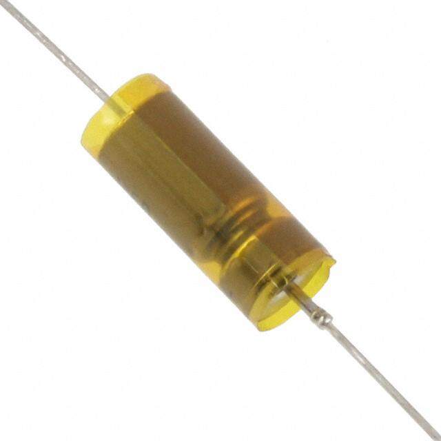
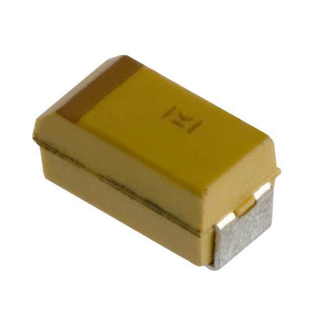
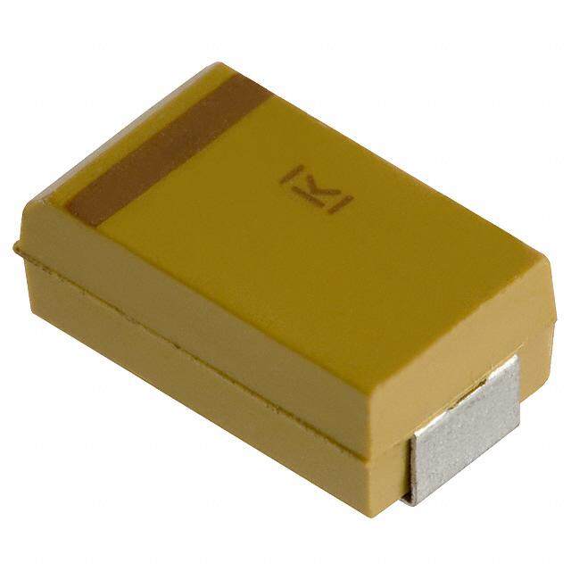
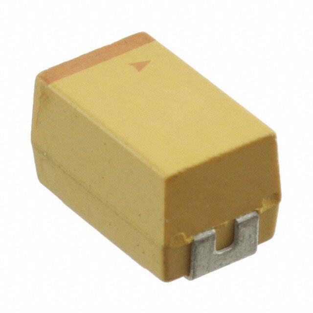
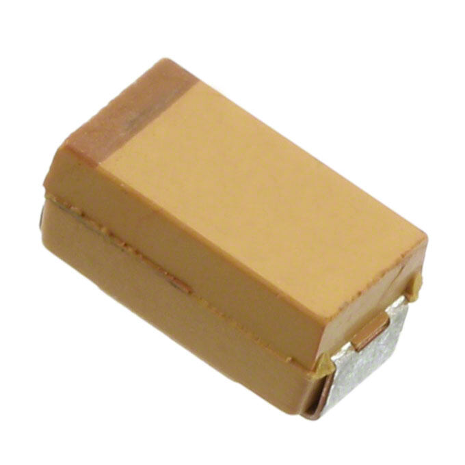
ICGOO电子元器件商城为您提供TPME107K020R0045由AVX设计生产,在icgoo商城现货销售,并且可以通过原厂、代理商等渠道进行代购。 TPME107K020R0045价格参考。AVXTPME107K020R0045封装/规格:钽电容器, 100µF 模制 钽电容器 20V 2917(7343 公制) 45 毫欧。您可以下载TPME107K020R0045参考资料、Datasheet数据手册功能说明书,资料中有TPME107K020R0045 详细功能的应用电路图电压和使用方法及教程。
| 参数 | 数值 |
| 产品目录 | |
| 描述 | CAP TANT 100UF 20V 10% 2917钽质电容器-固体SMD 20volts 100uF ESR=45 |
| ESR | 45 mOhms |
| ESR(等效串联电阻) | 45 毫欧 |
| 产品分类 | |
| 品牌 | AVX |
| 产品手册 | |
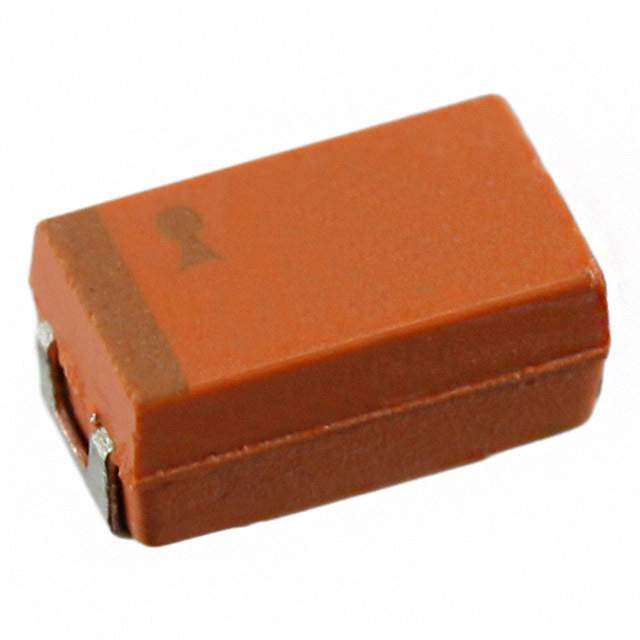
| 产品图片 |
|
| rohs | 符合RoHS无铅 / 符合限制有害物质指令(RoHS)规范要求 |
| 产品系列 | 钽电容器,钽质电容器-固体SMD,AVX TPME107K020R0045TPM |
| 数据手册 | |
| 产品型号 | TPME107K020R0045 |
| 不同温度时的使用寿命 | - |
| 产品 | Tantalum Solid Low ESR Standard Grade |
| 产品培训模块 | http://www.digikey.cn/PTM/IndividualPTM.page?site=cn&lang=zhs&ptm=21795 |
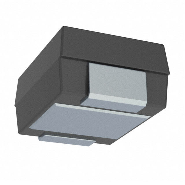
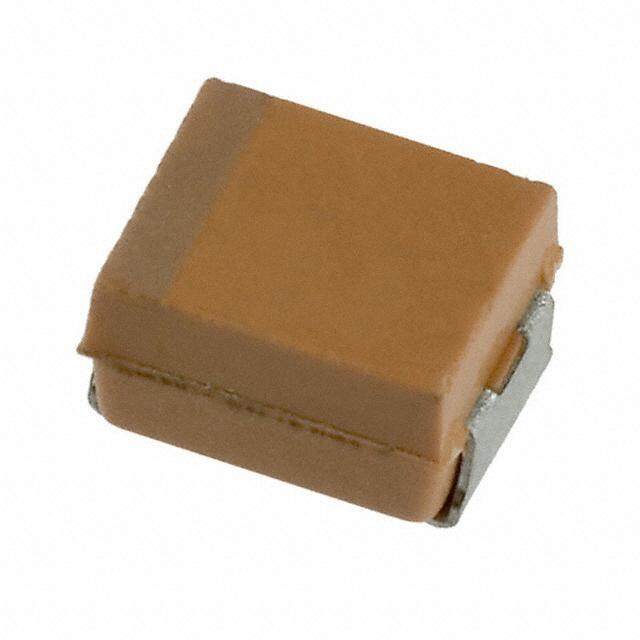
| 产品目录绘图 |
|
| 产品目录页面 | |
| 产品种类 | 钽质电容器-固体SMD |
| 其它名称 | 478-3637-2 |
| 制造商尺寸代码 | E |
| 制造商库存号 | E Case |
| 包装 | 带卷 (TR) |
| 商标 | AVX |
| 外壳代码-in | 2917 |
| 外壳代码-mm | 7343 |
| 外壳宽度 | 4.3 mm |
| 外壳长度 | 7.3 mm |
| 大小/尺寸 | 0.287" 长x 0.169" 宽(7.30mm x 4.30mm) |
| 安装类型 | 表面贴装 |
| 容差 | 10 % |
| 封装 | Reel |
| 封装/外壳 | 2917(7343 公制) |
| 封装/箱体 | 2917 (7343 metric) |
| 工作温度 | -55°C ~ 125°C |
| 工作温度范围 | - 55 C to + 125 C |
| 工厂包装数量 | 400 |
| 引线间距 | - |
| 损耗因数DF | 6 |
| 标准包装 | 400 |
| 特性 | 通用 |
| 电压-额定 | 20V |
| 电压额定值 | 20 V |
| 电容 | 100 uF |
| 端接类型 | SMD/SMT |
| 类型 | 模制 |
| 系列 | TPM |
| 高度 | 4.3 mm |
| 高度-安装(最大值) | 0.169"(4.30mm) |


- 商务部:美国ITC正式对集成电路等产品启动337调查
- 曝三星4nm工艺存在良率问题 高通将骁龙8 Gen1或转产台积电
- 太阳诱电将投资9.5亿元在常州建新厂生产MLCC 预计2023年完工
- 英特尔发布欧洲新工厂建设计划 深化IDM 2.0 战略
- 台积电先进制程称霸业界 有大客户加持明年业绩稳了
- 达到5530亿美元!SIA预计今年全球半导体销售额将创下新高
- 英特尔拟将自动驾驶子公司Mobileye上市 估值或超500亿美元
- 三星加码芯片和SET,合并消费电子和移动部门,撤换高东真等 CEO
- 三星电子宣布重大人事变动 还合并消费电子和移动部门
- 海关总署:前11个月进口集成电路产品价值2.52万亿元 增长14.8%
PDF Datasheet 数据手册内容提取
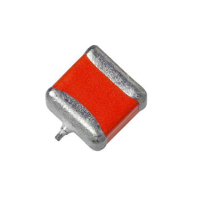
TPM Multianode Tantalum Ultra Low ESR Capacitor FEATURES • Multi-anode construction • Super low ESR • CV range: 10-2200μF / 2.5-50V LEAD-FREE COMPATIBLE COMPONENT • 5 case sizes available SnPb termination option is not RoHS compliant. • “Mirror” multi-anode construction used with D, Y case capacitors reduces ESL to half APPLICATIONS • High power DC/DC general applications MULTIANODE MULTIANODE TPM D, Y LOW SELF CONSTRUCTION INDUCTANCE CONSTRUCTION “MIRROR” DESIGN MARKING D, E, U, V, Y CASE CASE DIMENSIONS: millimeters (inches) AVX LOGO C22a7p a=c 2it2a0nµcFe Value in pF Code CEoIdAe MEeItAric (L0±.00.0280) W-+00.1.200 ( 0(0.0.00048)) H-+00.1.200 ( 0(0.0.00048)) W(01.±000.82)0 A-+00.2.300 ( 0(0.0.00182)) S Min. PBoalnadri ty 227 A RA a=t e1d0 VVoltage Code D 2917 7343-31 7.30 (0.287) 4.30 (0.169) 2.90 (0.114) 2.40 (0.094) 1.30 (0.051) 4.40 (0.173) (Anode+) XXXXX ID Code E 2917 7343-43 7.30 (0.287) 4.30 (0.169) 4.10 (0.162) 2.40 (0.094) 1.30 (0.051) 4.40 (0.173) U 2924 7361-43 7.30 (0.287) 6.10 (0.240) 4.10 (0.162) 3.10 (0.122) 1.30 (0.051) 4.40 (0.173) V 2924 7361-38 7.30 (0.287) 6.10 (0.240) 3.55 (0.140) 3.10 (0.122) 1.30 (0.051) 4.40 (0.173) Y 2917 7343-20 7.30 (0.287) 4.30 (0.169) 2.00 (0.079) max 2.40 (0.094) 1.30 (0.051) 4.40 (0.173) W1 dimension applies to the termination width for A dimensional area only. HOW TO ORDER TPM E 108 M 004 R 0018 Type Case Size Capacitance Code Tolerance Rated DC Voltage Packaging ESR in mΩ See table pF code: 1st two digits K = ±10% 002=2.5Vdc R = Pure Tin 7" Reel above represent significant M = ±20% 004=4Vdc S = Pure Tin 13" Reel figures, 3rd digit 006=6.3Vdc H = Tin Lead 7" Reel represents multiplier 010=10Vdc (Contact Manufacturer) (number of zeros to 016=16Vdc K = Tin Lead 13" Reel follow) 020=20Vdc (Contact Manufacturer) 025=25Vdc H, K = Non RoHS 035=35Vdc 050=50Vdc TECHNICAL SPECIFICATIONS Technical Data: All technical data relate to an ambient temperature of +25°C Capacitance Range: 10 μF to 2200 μF Capacitance Tolerance: ±10%, ±20% Rated Voltage (V ) ≤ +85°C: 2.5 4 6.3 10 16 20 25 35 50 R Category Voltage (V ) ≤ +125°C: 1.7 2.7 4 7 10 13 17 23 33 C Surge Voltage (V ) ≤ +85°C: 3.3 5.2 8 13 20 26 32 46 65 S Surge Voltage (V ) ≤ +125°C: 2.2 3.4 5 8 13 16 20 28 40 S Temperature Range: -55°C to +125°C Reliability: 1% per 1000 hours at 85°C, V with 0.1Ω/V series impedance, 60% confidence level R 96 The Important Information/Disclaimer is incorporated in these specifications by reference and should be reviewed in full before placing any order. 031320
TPM Multianode Tantalum Ultra Low ESR Capacitor CAPACITANCE AND RATED VOLTAGE RANGE (LETTER DENOTES CASE SIZE) Capacitance Rated Voltage DC (V ) to 85°C R μF Code 2.5V (e) 4V (G) 6.3V (J) 10V (A) 16V (C) 20V (D) 25V (E) 35V (V) 50V (T) 6.8 685 D(140) 10 106 E(120) 15 156 E(75,100) D(70) 22 226 E(75,100) E(60,100) 33 336 D(65) E(50,65) 47 476 D(100) D(45,55) D(55)/E(65) E(55,65) 68 686 D(40,50) E(45,55) 100 107 Y(45)(M) D(40,50) E(35,45) E(45,60) 150 157 Y(45)(M) E(30,40) E(35) E(25,40) 220 227 Y(30)(M) D(35) U(30,40) D(35) 330 337 D(25,35) D(25,35) E(50) E(23,35) D(30) E(23,30) 470 477 D(25,35) E(18,23,30) U(23,30) E(18,23) D(25) 680 687 U(18,23) E(18,23) V(23) D(25,45) E(18,23) E(25)(M) 1000 108 D(25) U(18,23) V(20)(M) V(18) E(12,15,18) 1500 158 E(15,18) U(18,23) 2200 228 E(18)(M) Released ratings (M tolerance only), (ESR ratings in mOhms in parentheses) Note: Voltage ratings are minimum values. AVX reserves the right to supply higher voltage ratings in the same case size, to the same reliability standards. The Important Information/Disclaimer is incorporated in these specifications 97 by reference and should be reviewed in full before placing any order. 030920
TPM Multianode Tantalum Ultra Low ESR Capacitor RATINGS & PART NUMBER REFERENCE PaArVt NXo. CSaizsee Capa(μcFit)ance VRo(alVttae)gde TemR(paºetCer)adt ure CVaot(elVtga)goery TeCma(ptºeeCgr)aotruyr e M(DμCaAxL). M(D%aFx). @ 1(MEm0Sa0ΩRxk).Hz 25º1C00kHz R8M5SºC Current 1(A2)5ºC MSL 2.5 Volt @ 85°C TPMD108*002#0025 D 1000 2.5 85 1.7 125 25 8 25 3.194 2.874 1.277 3 TPME158*002#0012 E 1500 2.5 85 1.7 125 38 6 12 4.743 4.269 1.897 3 TPME158*002#0015 E 1500 2.5 85 1.7 125 38 6 15 4.243 3.818 1.697 3 TPME158*002#0018 E 1500 2.5 85 1.7 125 38 6 18 3.873 3.486 1.549 3 TPMU158*002R0018 U 1500 2.5 85 1.7 125 30 6 18 4.048 3.643 1.619 3 TPMU158*002R0023 U 1500 2.5 85 1.7 125 30 6 23 3.581 3.223 1.433 3 TPME228M002#0018 E 2200 2.5 85 1.7 125 44 10 18 3.873 3.486 1.549 3 4 Volt @ 85°C TPMD337*004#0025 D 330 4 85 2.7 125 13.2 8 25 3.194 2.874 1.277 3 TPMD337*004#0035 D 330 4 85 2.7 125 13.2 8 35 2.699 2.429 1.080 3 TPMD477*004#0025 D 470 4 85 2.7 125 18.8 8 25 3.194 2.874 1.277 3 TPMD477*004#0035 D 470 4 85 2.7 125 18.8 8 35 2.699 2.429 1.080 3 TPMD687*004#0025 D 680 4 85 2.7 125 27.2 8 25 3.194 2.874 1.277 3 TPME687*004#0018 E 680 4 85 2.7 125 27 6 18 3.873 3.486 1.549 3 TPME687*004#0023 E 680 4 85 2.7 125 27 6 23 3.426 3.084 1.370 3 TPMD108*004#0025 D 1000 4 85 2.7 125 40 8 25 3.194 2.874 1.277 3 TPMD108*004#0045 D 1000 4 85 2.7 125 40 8 45 2.380 2.142 0.952 3 TPME108*004#0018 E 1000 4 85 2.7 125 40 6 18 3.873 3.486 1.549 3 TPME108*004#0023 E 1000 4 85 2.7 125 40 6 23 3.426 3.084 1.370 3 TPMU108*004R0018 U 1000 4 85 2.7 125 40 6 18 4.048 3.643 1.619 3 TPMU108*004R0023 U 1000 4 85 2.7 125 40 6 23 3.581 3.223 1.433 3 TPMV108*004#0018 V 1000 4 85 2.7 125 40 6 18 3.979 3.581 1.592 3 TPME158*004#0015 E 1500 4 85 2.7 125 60 6 15 4.243 3.818 1.697 3 TPME158*004#0018 E 1500 4 85 2.7 125 60 6 18 3.873 3.486 1.549 3 6.3 Volt @ 85°C TPMY227M006#0030 Y 220 6.3 85 4 125 13.2 6 30 2.646 2.381 1.058 3 TPMD337*006#0025 D 330 6.3 85 4 125 19.8 8 25 3.194 2.874 1.277 3 TPMD337*006#0035 D 330 6.3 85 4 125 19.8 8 35 2.699 2.429 1.080 3 TPMD477*006#0030 D 470 6.3 85 4 125 28.2 8 30 2.915 2.624 1.166 3 TPME477*006#0018 E 470 6.3 85 4 125 28 6 18 3.873 3.486 1.549 3 TPME477*006#0023 E 470 6.3 85 4 125 28 6 23 3.426 3.084 1.370 3 TPME477*006#0030 E 470 6.3 85 4 125 28 6 30 3.000 2.700 1.200 3 TPME687*006#0018 E 680 6.3 85 4 125 41 6 18 3.873 3.486 1.549 3 TPME687*006#0023 E 680 6.3 85 4 125 41 6 23 3.426 3.084 1.370 3 TPMU687*006R0018 U 680 6.3 85 4 125 41 6 18 4.048 3.643 1.619 3 TPMU687*006R0023 U 680 6.3 85 4 125 41 6 23 3.581 3.223 1.433 3 TPMV687*006#0023 V 680 6.3 85 4 125 41 6 23 3.520 3.168 1.408 3 TPME108M006#0025 E 1000 6.3 85 4 125 63 8 25 3.286 2.958 1.315 3 TPMV108M006#0020 V 1000 6.3 85 4 125 63 8 20 3.775 3.397 1.510 3 10 Volt @ 85°C TPMY107M010#0045 Y 100 10 85 7 125 10 8 45 2.160 1.944 0.864 3 TPMY157M010#0045 Y 150 10 85 7 125 15 8 45 2.160 1.944 0.864 3 TPMD227*010#0035 D 220 10 85 7 125 22 8 35 2.699 2.429 1.080 3 TPMD337*010#0035 D 330 10 85 7 125 33 8 35 2.699 2.429 1.080 3 TPME337*010#0023 E 330 10 85 7 125 33 6 23 3.426 3.084 1.370 3 TPME337*010#0035 E 330 10 85 7 125 33 6 35 2.777 2.500 1.111 3 TPME477*010#0023 E 470 10 85 7 125 47 6 23 3.426 3.084 1.370 3 TPME477*010#0030 E 470 10 85 7 125 47 6 30 3.000 2.700 1.200 3 TPMU477*010R0023 U 470 10 85 7 125 47 8 23 3.581 3.223 1.433 3 TPMU477*010R0030 U 470 10 85 7 125 47 8 30 3.136 2.822 1.254 3 16 Volt @ 85°C TPMD476*016#0100 D 47 16 85 10 125 7.5 8 100 1.597 1.437 0.639 3 TPMD686*016#0040 D 68 16 85 10 125 10.9 8 40 2.525 2.272 1.010 3 TPMD686*016#0050 D 68 16 85 10 125 10.9 8 50 2.258 2.032 0.903 3 TPMD107*016#0040 D 100 16 85 10 125 16 8 40 2.525 2.272 1.010 3 TPMD107*016#0050 D 100 16 85 10 125 16 8 50 2.258 2.032 0.903 3 TPME157*016#0030 E 150 16 85 10 125 24 6 30 3.000 2.700 1.200 3 TPME157*016#0040 E 150 16 85 10 125 24 6 40 2.598 2.338 1.039 3 TPME227*016#0025 E 220 16 85 10 125 35 6 25 3.286 2.958 1.315 3 TPME227*016#0040 E 220 16 85 10 125 35 6 40 2.598 2.338 1.039 3 TPMU227*016R0030 U 220 16 85 10 125 35 8 30 3.136 2.822 1.254 3 TPMU227*016R0040 U 220 16 85 10 125 35 8 40 2.716 2.444 1.086 3 TPME337*016#0050 E 330 16 85 10 125 52.8 10 50 2.324 2.091 0.930 3 20 Volt @ 85°C TPMD476*020#0045 D 47 20 85 13 125 9.4 8 45 2.380 2.142 0.952 3 TPMD476*020#0055 D 47 20 85 13 125 9.4 8 55 2.153 1.938 0.861 3 TPME107*020#0035 E 100 20 85 13 125 20 6 35 2.777 2.500 1.111 3 TPME107*020#0045 E 100 20 85 13 125 20 6 45 2.449 2.205 0.980 3 TPME157*020#0035 E 150 20 85 13 125 30 10 35 2.777 2.500 1.111 3 98 The Important Information/Disclaimer is incorporated in these specifications by reference and should be reviewed in full before placing any order. 071119
TPM Multianode Tantalum Ultra Low ESR Capacitor RATINGS & PART NUMBER REFERENCE PaArVt NXo. CSaizsee Capa(μcFit)ance VRo(alVttae)gde TemR(paºetCer)adt ure CVaot(elVtga)goery TeCma(ptºeeCgr)aotruyr e M(DμCaAxL). M(D%aFx). @ 1(MEm0Sa0ΩRxk).Hz 25º1C00kHz R8M5SºC Current 1(A2)5ºC MSL 25 Volt @ 85°C TPMD336*025#0065 D 33 25 85 17 125 8.3 8 65 1.981 1.783 0.792 3 TPMD476*025#0055 D 47 25 85 17 125 11.8 8 55 2.153 1.938 0.861 3 TPME476*025#0065 E 47 25 85 17 125 11.8 6 65 2.038 1.834 0.815 3 TPME686*025#0045 E 68 25 85 17 125 17 6 45 2.449 2.205 0.980 3 TPME686*025#0055 E 68 25 85 17 125 17 6 55 2.216 1.994 0.886 3 TPME107*025#0045 E 100 25 85 17 125 25 14 45 2.449 2.205 0.980 3 TPME107*025#0060 E 100 25 85 17 125 25 14 60 2.121 1.909 0.849 3 35 Volt @ 85°C TPMD226*035#0070 D 22 35 85 23 125 7.7 8 70 1.909 1.718 0.763 3 TPME226*035#0060 E 22 35 85 23 125 8 6 60 2.121 1.909 0.849 3 TPME226*035#0100 E 22 35 85 23 125 8 6 100 1.643 1.479 0.657 3 TPME336*035#0050 E 33 35 85 23 125 12 6 50 2.324 2.091 0.930 3 TPME336*035#0065 E 33 35 85 23 125 12 6 65 2.038 1.834 0.815 3 TPME476*035#0055 E 47 35 85 23 125 16 6 55 2.216 1.994 0.886 3 TPME476*035#0065 E 47 35 85 23 125 16 6 65 2.038 1.834 0.815 3 50 Volt @ 85°C TPMD106*050#0140 D 10 50 85 33 125 5 8 140 1.350 1.215 0.540 3 TPME106*050#0120 E 10 50 85 33 125 5 6 120 1.500 1.350 0.600 3 TPME156*050#0075 E 15 50 85 33 125 7.5 6 75 1.897 1.708 0.759 3 TPME156*050#0100 E 15 50 85 33 125 7.5 6 100 1.643 1.479 0.657 3 TPME226*050#0075 E 22 50 85 33 125 11 8 75 1.897 1.708 0.759 3 TPME226*050#0100 E 22 50 85 33 125 11 8 100 1.643 1.479 0.657 3 Moisture Sensitivity Level (MSL) is defined according to J-STD-020 All technical data relates to an ambient temperature of +25°C. Capacitance and DF are measured at 120Hz, 0.5V RMS with a maximum DC bias of 2.2 volts. DCL is measured at rated voltage after 5 minutes. The EIA & CECC standards for low ESR Solid Tantalum Capacitors allow an ESR movement to 1.25 times catalogue limit post mounting. For typical weight and composition see page 274. NOTE: AVX reserves the right to supply higher voltage ratings or tighter tolerance part in the same case size, to the same reliability standards. QUALIFICATION TABLE TPM series (Temperature range -55ºC to +125ºC) TEST Condition Characteristics Visual examination no visible damage Apply rated voltage (Ur) at 85ºC and / or category- DCL initial limit voltage (Uc) at 125ºC for 2000 hours through a Endurance ΔC/C within ±10% of initial value circuit impedance of ≤0.1Ω/V. Stabilize at room DF initial limit temperature for 1-2 hours before measuring. ESR 1.25 x initial limit Visual examination no visible damage Store at 65ºC and 95% relative humidity for 500 DCL 1.5 x initial limit hours, with no applied voltage. Stabilize at room Humidity ΔC/C within ±10% of initial value temperature and humidity for 1-2 hours before DF 1.2 x initial limit measuring. ESR 1.25 x initial limit Step Temperature°C Duration(min) +20ºC -55ºC +20ºC +85ºC +125ºC +20ºC 1 +20 15 DCL IL* n/a IL* 10 x IL* 12.5 x IL* IL* Temperature 2 -55 15 3 +20 15 ΔC/C n/a +0/-10% ±5% +10/-0% +12/-0% ±5% Stability 4 +85 15 DF IL* 1.5 x IL* IL* 1.5 x IL* 2 x IL* IL* 5 +125 15 6 +20 15 ESR 1.25 x IL* 2.5 x IL* 1.25 x IL* 1.25 x IL* 1.25 x IL* 1.25 x IL* Visual examination no visible damage Apply 1.3x category voltage (Uc) at 125ºC for DCL initial limit Surge 1000 cycles of duration 6 min (30 sec charge, ΔC/C within ±5% of initial value Voltage 5 min 30 sec discharge) through a charge / DF initial limit discharge resistance of 1000Ω ESR 1.25 x initial limit Visual examination no visible damage DCL initial limit Mechanical MIL-STD-202, Method 213, Condition C ΔC/C within ±5% of initial value Shock DF initial limit ESR initial limit Visual examination no visible damage DCL initial limit Vibration MIL-STD-202, Method 204, Condition D ΔC/C within ±5% of initial value DF initial limit ESR initial limit *Initial Limit The Important Information/Disclaimer is incorporated in these specifications 99 by reference and should be reviewed in full before placing any order. 031320
TPM Multianode Tantalum Ultra Low ESR Capacitor AVX SOLID ELECTROLYTIC CAPACITOR ROADMAP CONDUCTIVE CONVENTIONAL NIOBIUM POLYMER TANTALUM OXIDE TC Series T Series N Series T Cx T xx N xx F Series F Series F38 F xx – conductive – MnO – MnO CATHODE 2 2 polymer DIELECTRIC Ta O Ta O NbO 2 5 2 5 2 5 ANODE Niobium + Tantalum + Tantalum + Oxide FIVE CAPACITOR CONSTRUCTION STYLES J-lead Undertab TACmicrochip® Conformal Hermetic SERIES LINE UP: CONVENTIONAL SMD MnO 2 THJ TMJ THH F97-HT3 F9H professional 230°C 200°C low DCL Hermetic 135°C auto 150°C auto Industrial & THJ TRJ TRM F91-AJ6 F97 F98-AJ6 low DCL Automotive 175°C auto professional multianode auto professional auto TAJ TPS F93-AJ6 auto *T/*U auto *T/*U auto TPM F93-BE TPS multianode Low DCL Standard TAJ F91 F93 Standard TAJ TAC TPC F92 Low Profile Low Profile microchip microchip Low ESR High CV TLN TLJ TLC F98-AS1 F98 undertab microchip undertab, fused undertab 100 The Important Information/Disclaimer is incorporated in these specifications by reference and should be reviewed in full before placing any order. 031320
IMPORTANT INFORMATION/DISCLAIMER All product specifications, statements, information and data (collectively, the “Information”) in this datasheet or made available on the website are subject to change. The customer is responsible for checking and verifying the extent to which the Information contained in this publication is applicable to an order at the time the order is placed. All Information given herein is believed to be accurate and reliable, but it is presented without guarantee, warranty, or responsibility of any kind, expressed or implied. Statements of suitability for certain applications are based on AVX’s knowledge of typical operating conditions for such applications, but are not intended to constitute and AVX specifically disclaims any warranty concerning suitability for a specific customer application or use. ANY USE OF PRODUCT OUTSIDE OF SPECIFICATIONS OR ANY STORAGE OR INSTALLATION INCONSISTENT WITH PRODUCT GUIDANCE VOIDS ANY WARRANTY. The Information is intended for use only by customers who have the requisite experience and capability to determine the correct products for their application. Any technical advice inferred from this Information or otherwise provided by AVX with reference to the use of AVX’s products is given without regard, and AVX assumes no obligation or liability for the advice given or results obtained. Although AVX designs and manufactures its products to the most stringent quality and safety standards, given the current state of the art, isolated component failures may still occur. Accordingly, customer applications which require a high degree of reliability or safety should employ suitable designs or other safeguards (such as installation of protective circuitry or redundancies) in order to ensure that the failure of an electrical component does not result in a risk of personal injury or property damage. Unless specifically agreed to in writing, AVX has not tested or certified its products, services or deliverables for use in high risk applications including medical life support, medical device, direct physical patient contact, water treatment, nuclear facilities, weapon systems, mass and air transportation control, flammable environments, or any other potentially life critical uses. Customer understands and agrees that AVX makes no assurances that the products, services or deliverables are suitable for any high-risk uses. Under no circumstances does AVX warrant or guarantee suitability for any customer design or manufacturing process. Although all product–related warnings, cautions and notes must be observed, the customer should not assume that all safety measures are indicted or that other measures may not be required. The Important Information/Disclaimer is incorporated in these specifications by reference and should be reviewed in full before placing any order. 121119