ICGOO在线商城 > TMP103EVM
 Datasheet下载
- 型号: TMP103EVM
- 制造商: Texas Instruments
- 库位|库存: xxxx|xxxx
- 要求:
| 数量阶梯 | 香港交货 | 国内含税 |
| +xxxx | $xxxx | ¥xxxx |
查看当月历史价格
查看今年历史价格
TMP103EVM产品简介:
ICGOO电子元器件商城为您提供TMP103EVM由Texas Instruments设计生产,在icgoo商城现货销售,并且可以通过原厂、代理商等渠道进行代购。 提供TMP103EVM价格参考¥1126.62-¥1126.62以及Texas InstrumentsTMP103EVM封装/规格参数等产品信息。 你可以下载TMP103EVM参考资料、Datasheet数据手册功能说明书, 资料中有TMP103EVM详细功能的应用电路图电压和使用方法及教程。
| 参数 | 数值 |
| 产品目录 | 编程器,开发系统半导体 |
| 描述 | EVAL MODULE FOR TMP103温度传感器开发工具 TMP103 Eval Mod |
| 产品分类 | |
| 品牌 | Texas Instruments |
| 产品手册 | |
| 产品图片 |
|
| rohs | 否含铅 / 不受限制有害物质指令(RoHS)规范要求限制 |
| 产品系列 | 传感器开发工具,温度传感器开发工具,Texas Instruments TMP103EVM- |
| 数据手册 | http://www.ti.com/lit/pdf/sbou099点击此处下载产品Datasheet |
| 产品型号 | TMP103EVM |
| 产品种类 | 温度传感器开发工具 |
| 传感器类型 | 温度 |
| 使用的IC/零件 | TMP103 |
| 其它名称 | 296-28391 |
| 制造商产品页 | http://www.ti.com/general/docs/suppproductinfo.tsp?distId=10&orderablePartNumber=TMP103EVM |
| 商标 | Texas Instruments |
| 嵌入式 | 否 |
| 工作电源电压 | 1.4 V to 3.6 V |
| 工作电源电流 | 3 uA |
| 工具用于评估 | TMP103 |
| 工厂包装数量 | 1 |
| 感应范围 | -40°C ~ 125°C |
| 所含物品 | 板,线缆 |
| 接口 | I²C, USB |
| 接口类型 | I2C, SMBus |
| 最大工作温度 | + 125 C |
| 最小工作温度 | - 40 C |
| 标准包装 | 1 |
| 灵敏度 | ±1°C |
| 电压-电源 | 5V,USB |


.jpg)


- 商务部:美国ITC正式对集成电路等产品启动337调查
- 曝三星4nm工艺存在良率问题 高通将骁龙8 Gen1或转产台积电
- 太阳诱电将投资9.5亿元在常州建新厂生产MLCC 预计2023年完工
- 英特尔发布欧洲新工厂建设计划 深化IDM 2.0 战略
- 台积电先进制程称霸业界 有大客户加持明年业绩稳了
- 达到5530亿美元!SIA预计今年全球半导体销售额将创下新高
- 英特尔拟将自动驾驶子公司Mobileye上市 估值或超500亿美元
- 三星加码芯片和SET,合并消费电子和移动部门,撤换高东真等 CEO
- 三星电子宣布重大人事变动 还合并消费电子和移动部门
- 海关总署:前11个月进口集成电路产品价值2.52万亿元 增长14.8%


PDF Datasheet 数据手册内容提取
User's Guide SBOU099A–January2011–RevisedApril2018 TMP103EVM Thisuser'sguidedescribesthecharacteristics,operation,anduseoftheTMP103EVMevaluationboard.It provides a detailed description of the hardware design. It discusses how to set up and configure the evaluation module (EVM) software, and reviews the hardware and various aspects of the software operation. This document also includes information regarding operating procedures and input/output connections, an electrical schematic, printed-circuit board (PCB) layout drawings, and a parts list for the TMP103EVM. Throughout this document, the terms evaluation board, evaluation module, and EVM are synonymouswiththeTMP103EVM. Contents 1 Overview ..................................................................................................................... 2 2 SystemSetup ................................................................................................................ 3 3 TheoryofOperation......................................................................................................... 4 4 TMP103EVMHardwareOverview......................................................................................... 5 5 TMP103EVMSoftwareSetup.............................................................................................. 8 6 TMP103EVMSoftwareOverview ....................................................................................... 12 7 TMP103EVMDocumentation............................................................................................. 18 8 BillofMaterials............................................................................................................. 20 ListofFigures 1 TypicalHardwareIncludedWiththeTMP103EVMKit.................................................................. 2 2 TMP103EVMHardwareSetup............................................................................................. 3 3 TMP103TestBoardBlockDiagram....................................................................................... 4 4 SM-USB-DIGPlatformBlockDiagram.................................................................................... 5 5 ConnectingtheUSBCabletotheSM-USB-DIGPlatform............................................................. 6 6 SM-USB-DIGPlatformDriverInstallationConfirmation................................................................ 6 7 10-PinRibbonCableExtender............................................................................................. 7 8 TMP103EVMWelcomeWindow........................................................................................... 8 9 TMP103EVMLicenseAgreements........................................................................................ 9 10 NILicenseAgreements.................................................................................................... 10 11 TMP103EVMInstallationDirectory...................................................................................... 10 12 SelectComponentsInstallation.......................................................................................... 11 13 TMP103EVMSoftwareAboutButton.................................................................................... 11 14 TMP103EVMSoftwareInterface:ProperOperation................................................................... 12 15 CommunicationErrorWithUSBDIGPlatform......................................................................... 12 16 TMP103EVMSoftware:ReadingfromRegisters...................................................................... 13 17 TMP103EVMSoftware:WritingtoRegisters........................................................................... 14 18 ConversionTimeSelectionDialog....................................................................................... 14 19 MaxTempFlagTrigger ................................................................................................... 15 20 TMP103EVMSoftware:RegisterTab................................................................................... 16 21 TMP103EVMSoftware:TestProcedure................................................................................ 17 22 TMP103EVM Schematic.................................................................................................. 18 23 TMP103EVMComponentLayout........................................................................................ 19 SBOU099A–January2011–RevisedApril2018 TMP103EVM 1 SubmitDocumentationFeedback Copyright©2011–2018,TexasInstrumentsIncorporated
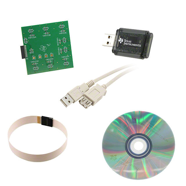
Overview www.ti.com Trademarks Microsoft,WindowsareregisteredtrademarksofMicrosoftCorporation. I2CisatrademarkofNXPSemiconductors. Allothertrademarksarethepropertyoftheirrespectiveowners. 1 Overview TheTMP103isadigitaloutputtemperaturesensorcapableofreadingtemperaturesto1°Cresolution. TheTMP103usesatwo-wire I2C™andSMBusinterfacethatsupportsglobalcommands.Theseglobal commandsallowtheusertocommunicatewithuptoeightTMP103devicesonthebuswithouthavingto sendindividualaddresses.TheTMP103isidealforenvironmentswithconstrainedspaceorpower- sensitiveapplications.TheTMP103isalsospecifiedtooperatebetween –40°Cand+125°C. 1.1 TMP103EVM Kit Contents Figure1 illustratesthetypicalhardwareincludedtheTMP103EVM.Table1 detailsthecontentsofthe TMP103EVMkit,ContacttheTexasInstrumentsProductInformationCenter(PIC) nearestyouifany componentismissing.TIhighlyrecommendsthatyouchecktheTIwebsiteathttp://www.ti.com toverify thatyouhavethelatestversionsoftherelatedsoftware. Figure1.TypicalHardwareIncludedWiththeTMP103EVMKit Table1.TMP103EVMKitContents Item Quantity TMP103PCBTestBoard 1 SM-USB-DIGPlatformPCB 1 USBCableExtender 1 10-pinConnectorRibbonCable 1 Extender 2 TMP103EVM SBOU099A–January2011–RevisedApril2018 SubmitDocumentationFeedback Copyright©2011–2018,TexasInstrumentsIncorporated
www.ti.com Overview 1.2 If You Need Assistance IfyouhavequestionsabouttheTMP103EVM,contacttheTemperatureSensingApplicationsTeamby postingonE2Eforumhere:https://e2e.ti.com/support/sensor/temperature_sensors/. 1.3 Related Documentation ThefollowingdocumentsprovideinformationregardingTexasInstrumentsintegratedcircuitsusedinthe assemblyoftheTMP103EVM.Thisuser'sguideisavailablefromtheTIwebsiteunderliteraturenumber SBOU099.Anyletterappendedtotheliteraturenumbercorrespondstothedocumentrevisionthatis currentatthetimeofthewritingofthisdocument.NewerrevisionsmaybeavailablefromtheTIwebsite athttp://www.ti.com,orcalltheTexasInstrumentsLiteratureResponseCenterat(800)477-8924orthe ProductInformationCenterat(972)644-5580.Whenordering,identifythedocumentbybothtitleand literaturenumber. Table2.RelatedDocumentation Document LiteratureNumber TMP103ProductDataSheet SBOS545 SM-USB-DIGPlatformUser’s SBOU098 Guide 1.4 FCC Warning Thisequipmentisintendedforuseinalaboratorytestenvironmentonly.Itgenerates,uses,andcan radiateradiofrequencyenergyandhasnotbeentestedforcompliancewiththelimitsofcomputing devicespursuanttosubpartJofpart15ofFCCrules,whicharedesignedtoprovidereasonable protectionagainstradiofrequencyinterference.Operationofthisequipmentinotherenvironmentsmay causeinterferencewithradiocommunications,inwhichcasetheuserisrequiredtotakewhatever measuresmayberequiredtocorrectthisinterferenceattheirownexpense. 2 System Setup TheTMP103EVMhardwareconsistsoftheSM-USB-DIGPlatformandtheTMP103EVM;theseunitsare easilyconnectedthrougha10-pin,board-to-boardconnectorthatshouldbeattachedtotheSM-USB-DIG andTMP103EVMPCBs.Oncethesetwoboardsareconnected,simplyplugtheUSBdevicefromtheSM- DIGintothecomputerasshowninFigure2. Desktop or Lab Computer/ SM-USB-DIG Platform TMP103EVM Laptop Figure2.TMP103EVMHardwareSetup SBOU099A–January2011–RevisedApril2018 TMP103EVM 3 SubmitDocumentationFeedback Copyright©2011–2018,TexasInstrumentsIncorporated
TheoryofOperation www.ti.com 3 Theory of Operation TheTMP103EVMisverymodestinitsdesign,andonlyrequiresthetwo-wireI2Clines(SDAandSCLK) andV /GNDtosupplyaconstant3.3Vandpowerreturn,asshowninFigure3.TheTMP103EVMalso DUT hasseveraltestpointstomonitorthesesignallines,andground,incaseusersmaywanttousetheirown signalsorverifyI2Ccommunications. TMP A TMP B TMP C U1 TMP D TP1-4 or ct Pin ConneSocket I2Can Idn tVerDfUaTce Test PointHeaders 0- 1 TMP E TMP H TMP G TMP F Figure3.TMP103TestBoardBlockDiagram 3.1 Signal Definitions of H1 (10-Pin Male Connector Socket) Table3showsthepinoutforthe10-pinconnectorsocketusedtocommunicatebetweentheTMP103EVM andtheSM-USB-DIG.ItshouldbenotedthattheTMP103EVMonlyusesthenecessaryI2C communicationlines(Pins1and3)andtheV andGND(Pins6and8)pinstoissuecommandstothe DUT TMP103sensors. Table3.PinConnector PinonU1 Signal Description 1 I2C_SCL I2Cclocksignal(SCL) GPIO:Controloutputormeasure 2 CTRL/MEAS4 input 3 I2C_SDA1 I2Cdatasignal(SDA) GPIO:Controloutputormeasure 4 CTRL/MEAS5 input 5 SPI_DOUT1 SPIdataoutput(MOSI) SwitchableDUTpowersupply: 6 V +3.3V,+5V,Hi-Z DUT (disconnected).(1) 7 SPI_CLK SPIclocksignal(SCLK) 8 GND Powerreturn(GND) 9 SPI_CS1 SPIchipselectSignal(CS) 10 SPI_DIN1 SPIdatainput(MISO) (1) WhenV isHi-Z,alldigitalI/OsareHi-Zaswell. DUT 4 TMP103EVM SBOU099A–January2011–RevisedApril2018 SubmitDocumentationFeedback Copyright©2011–2018,TexasInstrumentsIncorporated
www.ti.com TheoryofOperation 3.2 Theory of Operation for the SM-USB-DIG Platform Figure4 showstheblockdiagramfortheSM-USB-DIGPlatform.Thisplatformisageneral-purposedata acquisitionsystemthatisusedonseveraldifferentTexasInstruments'evaluationmodules.Thedetailsof itsoperationareincludedinaseparatedocument,theSM-USB-DIGPlatformUser'sGuide(SBOU098), availablefordownloadatwww.ti.com).TheblockdiagraminFigure4ispresentedasabriefoverviewof thePlatform. ThecoreoftheSM-USB-DIGPlatformistheTUSB3210,an8052microcontroller(μC)thathasabuilt-in USBinterface.ThemicrocontrollerreceivesinformationfromthehostcomputerthatittranslatesintoI2C, SPI,orotherdigitalI/Opatterns.DuringthedigitalI/Otransaction,themicrocontrollerreadstheresponse ofanydeviceconnectedtotheI/Ointerface.TheresponsefromthedeviceisthensentbacktothePC whereitisinterpretedbythehostcomputer. +3.3V Regulator s plie V +3.3V p USB u +5V S r d Powe CUoSmBp fuBrotuemsr withT aU8UnS0dS5B BU2 3IAnm2RtC1eT0rface LevBeul fTferarsn salnadtors ICM2Coena/StsrPoulrI ea nBdits To Test n B a o r a e r t d u p m 8Kx8-byte SM USB DIG Platform o Power-On Reset EEPROM C o T V DUT +5.0V Power (Hi-Z, 3.3V, or 5V) Switched USB Power Switching Power +3.0V Figure4.SM-USB-DIGPlatformBlockDiagram 4 TMP103EVM Hardware Overview 4.1 Electrostatic Discharge Warning CAUTION Many of the components on the TMP103EVM are susceptible to damage by electrostatic discharge (ESD). Customers are advised to observe proper ESD handling precautions when unpacking and handling the EVM, including the use ofagroundedwriststrapatanapprovedESDworkstation. 4.2 Connecting the Hardware ToconnecttheTMP103TestBoardandtheSM-USB-DIGPlatformtogether,gentlyslidethemaleand femaleendsofthe10-pinconnectorstogether.Makesurethatthetwoconnectorsarecompletelypushed together;looseconnectionsmaycauseintermittentoperation. SBOU099A–January2011–RevisedApril2018 TMP103EVM 5 SubmitDocumentationFeedback Copyright©2011–2018,TexasInstrumentsIncorporated
TMP103EVMHardwareOverview www.ti.com 4.3 Connecting the USB Cable to the SM-USB-DIG Platform Figure5 depictstheUSBcableconnectedtotheSM-USB-DIGPlatform.Becarefulwheninsertingthe connectors. Figure5.ConnectingtheUSBCabletotheSM-USB-DIGPlatform Figure6 showsthetypicalsystemresponsewhentheSM-USB-DIGPlatformboardconnectstoaPC USBportforthefirsttime.Typically,thecomputerwillrespondwitha FoundNewHardware,USBDevice pop-updialog.Thepop-upwindowthengenerallychangestoFoundNewHardware,USBHuman InterfaceDevice.Thispop-upscreenindicatesthatthedeviceisreadytobeused.TheSM-USB-DIG Platformusesthehumaninterfacedevicedriversthatarepartofthe Microsoft®Windows® operating system. Figure6.SM-USB-DIGPlatformDriverInstallationConfirmation 6 TMP103EVM SBOU099A–January2011–RevisedApril2018 SubmitDocumentationFeedback Copyright©2011–2018,TexasInstrumentsIncorporated
www.ti.com TMP103EVMHardwareOverview 4.4 TMP103EVM Features ThissectiondescribessomeofthehardwarefeaturespresentontheTMP103testboard. 4.4.1 Populating0-ΩResistors TheTMP103testboardcontains0-Ωresistors(R1toR16)thatconnecttheindividualTMP103sensorsto theI2Cbuslines.Whentheseresistorsarepopulated,theybecomeavailableforcommunicationin generalcalls.Ifthe0-Ω resistorsarenotpopulatedforcertainTMP103devicesontheboard,theyarenot abletocommunicatewiththesoftwareorreceiveanyexternalI2Ccommands.Leavingtheresistors unpopulatedcouldbeusefulifoneoftheTMP103unitsbecomesdamagedorfewerthaneightTMP103s arepopulated. 4.4.2 MultipleTMP103Sensors TheTMP103EVMboardwasdesignedtotakeadvantageoftheI2CgeneralcalldescribedintheTMP103 productdatasheet.ThisfeatureallowsthesoftwaretocommunicatewithalltheTMP103ssimultaneously withoutrequiringindividualcommandswithseparatepointeraddressestothesensors.Themaximum numberofsensorsontheTMP103testboardiseight;alldeviceshaveseparatehardwareaddress,soa boardofeightpopulatedTMP103devicesrequireseightdifferentparttypes.Forassignmentofthepointer addressesandamoredetaileddescription,consulttheTMP103Low-Power,DigitalTemperatureSensor WithTwo-WireInterfaceinWCSP datasheet(SBOS545). 4.4.3 I2CTestPoints I2CtestpointsareincludedontheTMP103testboardforuserconvenience.Thesetestpointscanbe usedtomonitorthetwo-wirelinesoftheI2CinterfaceortoruntheTMP103testboardexternallywithout theuseoftheSM-USB-DIG. 4.4.4 Optional10-PinConnectorRibbonExtender TheTMP103EVMkitshipswithanoptionalribboncabletoextendtheconnectionbetweentheSM-USB- DIGandtheTMP103EVMPCB.Thiscablecanbeusefulifhightemperaturetestsmustberunonthetest board,becausetheSM-USB-DIGplatformisnotratedforhightemperatures.Toconnecttheribboncable, attachthecabletotheEVMandSM-USB-DIGPlatformboardasshowninFigure7. Figure7.10-PinRibbonCableExtender SBOU099A–January2011–RevisedApril2018 TMP103EVM 7 SubmitDocumentationFeedback Copyright©2011–2018,TexasInstrumentsIncorporated
TMP103EVMSoftwareSetup www.ti.com 5 TMP103EVM Software Setup ThissectiondiscusseshowtoinstalltheTMP103EVMsoftware. 5.1 Operating Systems Compatibility TheTMP103EVMsoftwarehasbeentestedontheMicrosoftWindows7.Thesoftwareshouldalso functiononotherWindowsoperatingsystemssuchasWindows10. 5.2 TMP103EVM Software Installation TheEVMsoftwareistestedontheMicrosoftWindows7and10operatingsystem(OS).Thesoftwarealso functionsonotherWindowsoperatingsystems.TheEVMsoftwareisavailablethroughtheEVMproduct folderontheTIwebsite.Todownloadthesoftwaretoyoursystem,simplyfollowstheinstructionsbelow. 1. GototheTMP103EVMwebpageontheTIwebsite:http://www.ti.com/tool/TMP103EVM.Scrolldown totheSoftwaresectionanddownloadthelatestevaluationsoftware. 2. Unzipthedownloadedfileintoaknowndirectory.Oncethefilesareextracted,navigateandrunthe Setup_TMP103EVM_GUI.exefilelocatedin[Unziplocation].TheEVMsoftwareinstallerthenbegins theinstallationprocessasshowninFigure8. Figure8.TMP103EVMWelcomeWindow 8 TMP103EVM SBOU099A–January2011–RevisedApril2018 SubmitDocumentationFeedback Copyright©2011–2018,TexasInstrumentsIncorporated
www.ti.com TMP103EVMSoftwareSetup 3. Followtheon-screeninstructionsbyclickingtheNextbuttontoinstallthesoftware.Followingthis option,twolicenseagreementsarepresentedasshowninFigure9andFigure10thatmustbe accepted.AfteracceptingboththeTexasInstrumentsandNationalInstrumentslicenseagreements, theuserisgiventhechoiceofselectingthedirectorytoinstalltheprogram;usually,TIrecommends choosingthedefaultsettingstoredintheC:\ProgramFiles\TMP103EVM pathasshowninFigure11. Figure9.TMP103EVMLicenseAgreements SBOU099A–January2011–RevisedApril2018 TMP103EVM 9 SubmitDocumentationFeedback Copyright©2011–2018,TexasInstrumentsIncorporated
TMP103EVMSoftwareSetup www.ti.com Figure10.NILicenseAgreements Figure11.TMP103EVMInstallationDirectory 10 TMP103EVM SBOU099A–January2011–RevisedApril2018 SubmitDocumentationFeedback Copyright©2011–2018,TexasInstrumentsIncorporated
www.ti.com TMP103EVMSoftwareSetup 4. Forfirst-timeinstallation,ensuretheLabVIEWRunTimeEngineislistedinthefollowingsummaryas showninFigure12.TMP103EVMGUIisrequiredLabVIEW2016f2runtimeengineforproper operation.OncetheNextbuttonisclicked,theprogressbaropensandshowstheinstallationofthe software.ItmaytakesometimetodownloadtheLabVIEWRunTimeEngineonthefirstinstallation. Usersmaybepromptedtodownloadthefilewheninstallingthesoftwareforthefirsttime,especiallyif theLabVIEWRunTimeEnginecheckboxischecked. Figure12.SelectComponentsInstallation 5.3 Software Description and Set-Up TheTMP103EVMsoftwareallowstheusertomonitortemperaturesfromeightseparateTMP103sensor units.Figure13showsthescreenthatdisplayswhenyoupressthe Aboutbuttontoverifythatyouhave thelatestversionofthesoftware. Figure13.TMP103EVMSoftware AboutButton SBOU099A–January2011–RevisedApril2018 TMP103EVM 11 SubmitDocumentationFeedback Copyright©2011–2018,TexasInstrumentsIncorporated
TMP103EVMSoftwareOverview www.ti.com 6 TMP103EVM Software Overview ThissectiondiscusseshowtousetheTMP103EVMsoftware. 6.1 Starting the TMP103EVM Software TheTMP103EVMsoftwarecanbeoperatedthroughthe Start menuinWindows.FromtheStart menu, selectAllPrograms;highlighttheTMP103folder,andthenselecttheTMP103EVMprogram.Figure14 illustrateshowthesoftwareshouldappeariftheTMP103EVMisfunctioningproperly. Figure14.TMP103EVMSoftwareInterface:ProperOperation Figure15showsanerrorthatpopsupifthecomputercannotcommunicatewiththeEVM.Ifyoureceive thiserror,firstensurethattheUSBcableisproperlyconnectedonbothends.Anotherpossiblesourcefor thiserrorisaproblemwithyourcomputerUSBHumanInterfaceDevicedriver.Makesurethatthedevice isrecognizedwhentheUSBcableispluggedin;recognitionisindicatedbyaWindows-generated confirmationsound. Figure15.CommunicationErrorWithUSBDIGPlatform 12 TMP103EVM SBOU099A–January2011–RevisedApril2018 SubmitDocumentationFeedback Copyright©2011–2018,TexasInstrumentsIncorporated
www.ti.com TMP103EVMSoftwareOverview 6.2 Using the TMP103EVM Software 6.2.1 ReadingfromRegisters WhenfirststartingtheTMP103EVMsoftware,usersareadvisedtoconfirmconnectionstotheboardby togglingtheContinuouslyReadAllRegister button(highlightedinFigure16).Ifalldevicesare communicatingcorrectly,theusershouldbeabletoseetemperaturechangeovertimeintheTMPGraph andtheindividualTMP103thermometers.AlegendisprovidedintheConfigurationSettingscolumnon theleftforthetemperaturegraph;refertoFigure17. Figure16.TMP103EVMSoftware:ReadingfromRegisters Analternativemethodforacquiringdataisthe ReadAllReg button,alsoindicatedinFigure16.This buttonisusefulwhiletheAuto-WriteRegbuttonistoggled,oriftheuserwantstotakeindividual measurementsonanon-standardtimeinterval. NOTE: TheusercannotcontinuouslypresseithertheReadAllRegistersortheAuto-Write Registersbutton. SBOU099A–January2011–RevisedApril2018 TMP103EVM 13 SubmitDocumentationFeedback Copyright©2011–2018,TexasInstrumentsIncorporated
TMP103EVMSoftwareOverview www.ti.com 6.2.2 WritingtoRegisters TheTMP103EVMsoftwarecontainstwodifferentmethodsforwritingdata: WriteAllRegandAuto-Write Reg.IndividuallywritingtheregisterswithoutAuto-Writecanbeusefulwhenadjustinglargenumbersof theconfigurationregistersontheleft.Also,iftheuserwishestochangesomeoftheconfigurationsettings ontheleftwhilecontinuouslyreadingregisters,heorshewillbepromptedwithablinking WriteAll Registersbutton.UntiltheWriteAllRegisters buttonhasbeenselected,theprogramstopspollingdata fromtheTMP103sensors.Conversely,theAuto-WriteRegistersfeatureautomaticallymakeschangesto theconfigurationregisterwheneveroneoftheconfigurationsettingsontheleftchanges,asindicatedin Figure17. Figure17.TMP103EVMSoftware:WritingtoRegisters 6.2.3 ConversionTime TheConversionTimeselectionbox,showninFigure18,isusedtochangethespeedatwhichthe TMP103sensorsmeasuretheambienttemperaturearoundthem.Ausermaywanttosettheconversion speedfasterifdatamustbegatheredfaster.Theusershouldbeawarethatincreasingtheconversion speedalsoincreasesthepowerconsumedbythedevices.Whilethisincreaseinpowerconsumptionmay notcauseanyissuesfortheTMP103EVM,usersmaywanttoreducepowerconsumptiononcertain applicationsorcustomboards.Usersshouldbecautiousofthisfeature. Figure18.ConversionTimeSelectionDialog 14 TMP103EVM SBOU099A–January2011–RevisedApril2018 SubmitDocumentationFeedback Copyright©2011–2018,TexasInstrumentsIncorporated
www.ti.com TMP103EVMSoftwareOverview 6.2.4 Max\MinTempandtheMax\MinTempFlag TheTMP103sensorhasabuilt-inflagtoindicatewhenadeviceismeasuringtemperaturesaboveor belowasetrange.Thisflagcanbeusefultonotifytheuserwhenambienttemperaturesgobeyonda desiredrange.TheTMP103sensormaximummeasurablevaluesarefrom–40°Cto+125°C.Whena temperatureviolatesthemaxormintempflag,therespectivetemptogglesonandremainsonuntilthe temperaturesreturntothedesignatedrange.TheTMP103Aisshownsignalingaflagbyviolatingthemax temperatureinFigure19. Figure19.MaxTempFlagTrigger 6.2.5 ConversiontoFahrenheit IftheuserdesiresthetemperaturethermometerstoperformmeasurementsindegreesFahrenheit,this settingcanbechangedindividuallybyclickingthecheckboxbeneaththethermometer.Iftheuserdesires tochangeallofthesesettingsatonce,simplytogglethe ToFahrenbuttoninthebottomright-handcorner ofthesoftwaredisplay.SeeFigure16. SBOU099A–January2011–RevisedApril2018 TMP103EVM 15 SubmitDocumentationFeedback Copyright©2011–2018,TexasInstrumentsIncorporated
TMP103EVMSoftwareOverview www.ti.com 6.2.6 RegistersTab TheRegisterstabdisplaystheindividualregistersettingfortheTMP103sensors.Itshouldbenotedthat theTMP103EVMsoftwarekeepsalltheconfigurationregisters,T registers,andT registers LOW HIGH identical.Formoreinformationontheindividualregistersandthebitmeanings,simplyhighlightthe desiredregisterandhittheHelpwithRegbuttonshowninFigure20. Figure20.TMP103EVMSoftware:RegisterTab TheRegisterstabalsoincludestwootherfeatures:the dig_bitstableandtheindividualtempreadfeature. Thedig_bitstableallowstheusertomonitorandchangeindividualbitsbyhighlightingthedesiredregister andtogglingthebitcontrolsbeneathit. NOTE: Onlywritableregisterbitscanbetoggled. Itisalsopossibletoindividuallyreadthetemperaturesensorsontheboardusingthe ReadTMP103 buttonintheRegisterstab.Thisactionyieldsthesameresultasthegeneral-callReadAllRegisters,but doesnotrequiretheothersensorstoberead.TheindividualreadofaTMPsensorismainlyincludedfor reference;TIrecommendsusingthe ReadAllReg buttonwhenperformingevaluationswiththe TMP103EVMsoftware. 16 TMP103EVM SBOU099A–January2011–RevisedApril2018 SubmitDocumentationFeedback Copyright©2011–2018,TexasInstrumentsIncorporated
www.ti.com TMP103EVMSoftwareOverview 6.2.7 RegisterTab:TestEVM TheRegistertabfortheTMP103EVMtestsoftwarealsoincludesasub-routineprogramtoverify communicationwiththeTMP103devicesandruntheTMP103testprocedures.Byclickingonthe Test EVMbutton(refertoFigure20),anewwindowappearsasshowninFigure21. Figure21.TMP103EVMSoftware:TestProcedure ThissecondaryprogramreadseachregisterindividuallyandverifiesthattheTMP103sensorsproduce therequirednumberofAcknowledgesfromthegeneralcallandindividualcommunication.Totestthe generalcall,usetheTestAllbutton.Totestthesensorsindividually,usethe TestTMPxbuttonnextto thecorrespondingLED. SBOU099A–January2011–RevisedApril2018 TMP103EVM 17 SubmitDocumentationFeedback Copyright©2011–2018,TexasInstrumentsIncorporated
TMP103EVMDocumentation www.ti.com 7 TMP103EVM Documentation ThissectioncontainsthecompletebillofmaterialsandapartialschematicdiagramfortheTMP103EVM. TheTMP103EVMSchematic(SBOR013)isavailablefordownloadthroughtheTIwebsite.Additional documentationfortheSM-USB-DIGPlatformcanbefoundintheSM-USB-DIGPlatformUser’sGuide (SBOU098)availablethroughtheTIwebsite. 7.1 TMP103EVM Board Schematic Figure22showstheTMP103EVMboardschematic. Figure22.TMP103EVMSchematic 18 TMP103EVM SBOU099A–January2011–RevisedApril2018 SubmitDocumentationFeedback Copyright©2011–2018,TexasInstrumentsIncorporated
www.ti.com TMP103EVMDocumentation 7.2 TMP103EVM PCB Components Layout Figure23illustratesthelayoutofthecomponentsfortheTMP103EVMboard. 2.0 in (5.08 cm) 2.0 in (5.08 cm) Figure23.TMP103EVMComponentLayout SBOU099A–January2011–RevisedApril2018 TMP103EVM 19 SubmitDocumentationFeedback Copyright©2011–2018,TexasInstrumentsIncorporated
BillofMaterials www.ti.com 8 Bill of Materials Table4showsthepartslist. Table4.BillofMaterials Item Qty RefDes Value Description Manufacturer PartNo Resistor,0.0OHM 1 16 R1-R16 0Ω StackpoleElectronics RMCF0402ZT0R00 1/16W0402SMD Resistor,51KOHM 2 2 R17,R18 51kΩ 1/10W5%0402 Panasonic ERJ-2GEJ513X SMD Capacitor,ceramic CC0402ZRY5V8BB 3 9 C1-C9 0.1μF 0.1μF25VY5V Yageo 104 0402 Ferritebead300Ω 4 1 FB1 – Wurth 74279272 .2A0402 5 8 TMP103A-H – TMP103 TexasInstruments Bumpon 6 4 Bumpons – hemisphere.50x.14 3M SJ-5312(CLEAR) clear SuperMiniDIG ConnsocketRT 1 connector – — — Ang50POS Socket 7 SuperMiniDIG ConnsocketRT Mill-Max 851-93-050-20- 1 connector – Ang50POS.050 Manufacturing 001000 Socket 20 TMP103EVM SBOU099A–January2011–RevisedApril2018 SubmitDocumentationFeedback Copyright©2011–2018,TexasInstrumentsIncorporated
www.ti.com RevisionHistory Revision History NOTE:Pagenumbersforpreviousrevisionsmaydifferfrompagenumbersinthecurrentversion. ChangesfromOriginal(January2011)toARevision .................................................................................................... Page • ChangedtheTMP103EVMSoftwareInstallationsection............................................................................ 8 • ChangedtheSuperMiniDIGconnectorSocketrows(Item#7)intheBillofMaterials........................................ 20 SBOU099A–January2011–RevisedApril2018 RevisionHistory 21 SubmitDocumentationFeedback Copyright©2011–2018,TexasInstrumentsIncorporated
EvaluationBoard/KitImportantNotice TexasInstruments(TI)providestheenclosedproduct(s)underthefollowingconditions: Thisevaluationboard/kitisintendedforuseforENGINEERINGDEVELOPMENT,DEMONSTRATION,OREVALUATIONPURPOSES ONLYandisnotconsideredbyTItobeafinishedend-productfitforgeneralconsumeruse.Personshandlingtheproduct(s)musthave electronicstrainingandobservegoodengineeringpracticestandards.Assuch,thegoodsbeingprovidedarenotintendedtobecomplete intermsofrequireddesign-,marketing-,and/ormanufacturing-relatedprotectiveconsiderations,includingproductsafetyandenvironmental measurestypicallyfoundinendproductsthatincorporatesuchsemiconductorcomponentsorcircuitboards.Thisevaluationboard/kitdoes notfallwithinthescopeoftheEuropeanUniondirectivesregardingelectromagneticcompatibility,restrictedsubstances(RoHS),recycling (WEEE),FCC,CEorUL,andthereforemaynotmeetthetechnicalrequirementsofthesedirectivesorotherrelateddirectives. Shouldthisevaluationboard/kitnotmeetthespecificationsindicatedintheUser’sGuide,theboard/kitmaybereturnedwithin30daysfrom thedateofdeliveryforafullrefund.THEFOREGOINGWARRANTYISTHEEXCLUSIVEWARRANTYMADEBYSELLERTOBUYER ANDISINLIEUOFALLOTHERWARRANTIES,EXPRESSED,IMPLIED,ORSTATUTORY,INCLUDINGANYWARRANTYOF MERCHANTABILITYORFITNESSFORANYPARTICULARPURPOSE. Theuserassumesallresponsibilityandliabilityforproperandsafehandlingofthegoods.Further,theuserindemnifiesTIfromallclaims arisingfromthehandlingoruseofthegoods.Duetotheopenconstructionoftheproduct,itistheuser’sresponsibilitytotakeanyandall appropriateprecautionswithregardtoelectrostaticdischarge. EXCEPTTOTHEEXTENTOFTHEINDEMNITYSETFORTHABOVE,NEITHERPARTYSHALLBELIABLETOTHEOTHERFORANY INDIRECT,SPECIAL,INCIDENTAL,ORCONSEQUENTIALDAMAGES. TIcurrentlydealswithavarietyofcustomersforproducts,andthereforeourarrangementwiththeuserisnotexclusive. TIassumesnoliabilityforapplicationsassistance,customerproductdesign,softwareperformance,orinfringementofpatentsor servicesdescribedherein. PleasereadtheUser’sGuideand,specifically,theWarningsandRestrictionsnoticeintheUser’sGuidepriortohandlingtheproduct.This noticecontainsimportantsafetyinformationabouttemperaturesandvoltages.ForadditionalinformationonTI’senvironmentaland/or safetyprograms,pleasecontacttheTIapplicationengineerorvisitwww.ti.com/esh. NolicenseisgrantedunderanypatentrightorotherintellectualpropertyrightofTIcoveringorrelatingtoanymachine,process,or combinationinwhichsuchTIproductsorservicesmightbeorareused. FCCWarning Thisevaluationboard/kitisintendedforuseforENGINEERINGDEVELOPMENT,DEMONSTRATION,OREVALUATIONPURPOSES ONLYandisnotconsideredbyTItobeafinishedend-productfitforgeneralconsumeruse.Itgenerates,uses,andcanradiateradio frequencyenergyandhasnotbeentestedforcompliancewiththelimitsofcomputingdevicespursuanttopart15ofFCCrules,whichare designedtoprovidereasonableprotectionagainstradiofrequencyinterference.Operationofthisequipmentinotherenvironmentsmay causeinterferencewithradiocommunications,inwhichcasetheuserathisownexpensewillberequiredtotakewhatevermeasuresmay berequiredtocorrectthisinterference. EVMWarningsandRestrictions ItisimportanttooperatethisEVMwithintheinputvoltagerangeof5.7V(min)to9V(max)andtheoutputvoltagerangeof0V(min)to5V (max). Exceedingthespecifiedinputrangemaycauseunexpectedoperationand/orirreversibledamagetotheEVM.Iftherearequestions concerningtheinputrange,pleasecontactaTIfieldrepresentativepriortoconnectingtheinputpower. Applyingloadsoutsideofthespecifiedoutputrangemayresultinunintendedoperationand/orpossiblepermanentdamagetotheEVM. PleaseconsulttheEVMUser'sGuidepriortoconnectinganyloadtotheEVMoutput.Ifthereisuncertaintyastotheloadspecification, pleasecontactaTIfieldrepresentative. Duringnormaloperation,somecircuitcomponentsmayhavecasetemperaturesgreaterthan+25°C.TheEVMisdesignedtooperate properlywithcertaincomponentsabove+25°Caslongastheinputandoutputrangesaremaintained.Thesecomponentsincludebutare notlimitedtolinearregulators,switchingtransistors,passtransistors,andcurrentsenseresistors.Thesetypesofdevicescanbeidentified usingtheEVMschematiclocatedintheEVMUser'sGuide.Whenplacingmeasurementprobesnearthesedevicesduringoperation, pleasebeawarethatthesedevicesmaybeverywarmtothetouch. MailingAddress:TexasInstruments,PostOfficeBox655303,Dallas,Texas75265 Copyright©2018,TexasInstrumentsIncorporated
STANDARDTERMSFOREVALUATIONMODULES 1. Delivery:TIdeliversTIevaluationboards,kits,ormodules,includinganyaccompanyingdemonstrationsoftware,components,and/or documentation which maybe providedtogether orseparately (collectively,an “EVM”or “EVMs”)totheUser (“User”)inaccordance withthetermssetforthherein.User'sacceptanceoftheEVMisexpresslysubjecttothefollowingterms. 1.1 EVMsareintendedsolelyforproductorsoftwaredevelopersforuseinaresearchanddevelopmentsettingtofacilitatefeasibility evaluation, experimentation, or scientific analysis of TI semiconductors products. EVMs have no direct function and are not finished products. EVMs shall not be directly or indirectly assembled as a part or subassembly in any finished product. For clarification,anysoftwareorsoftwaretoolsprovidedwiththeEVM(“Software”)shallnotbesubjecttothetermsandconditions setforthhereinbutrathershallbesubjecttotheapplicabletermsthataccompanysuchSoftware 1.2 EVMsarenotintendedforconsumerorhouseholduse.EVMsmaynotbesold,sublicensed,leased,rented,loaned,assigned, or otherwise distributed for commercial purposes by Users, in whole or in part, or used in any finished product or production system. 2 LimitedWarrantyandRelatedRemedies/Disclaimers: 2.1 ThesetermsdonotapplytoSoftware.Thewarranty,ifany,forSoftwareiscoveredintheapplicableSoftwareLicense Agreement. 2.2 TIwarrantsthattheTIEVMwillconformtoTI'spublishedspecificationsforninety(90)daysafterthedateTIdeliverssuchEVM toUser.Notwithstandingtheforegoing,TIshallnotbeliableforanonconformingEVMif(a)thenonconformitywascausedby neglect,misuseormistreatmentbyanentityotherthanTI,includingimproperinstallationortesting,orforanyEVMsthathave beenalteredormodifiedinanywaybyanentityotherthanTI,(b)thenonconformityresultedfromUser'sdesign,specifications or instructions for such EVMs or improper system design, or (c) User has not paid on time. Testing and other quality control techniques are used to the extent TI deems necessary. TI does not test all parameters of each EVM. User'sclaimsagainstTIunderthisSection2arevoidifUserfailstonotifyTIofanyapparentdefectsintheEVMswithinten(10) businessdaysafterdelivery,orofanyhiddendefectswithten(10)businessdaysafterthedefecthasbeendetected. 2.3 TI's sole liability shall be at its option to repair or replace EVMs that fail to conform to the warranty set forth above, or credit User's account for such EVM. TI's liability under this warranty shall be limited to EVMs that are returned during the warranty periodtotheaddressdesignatedbyTIandthataredeterminedbyTInottoconformtosuchwarranty.IfTIelectstorepairor replace such EVM, TI shall have a reasonable time to repair such EVM or provide replacements. Repaired EVMs shall be warranted for the remainder of the original warranty period. Replaced EVMs shall be warranted for a new full ninety (90) day warrantyperiod. 3 RegulatoryNotices: 3.1 UnitedStates 3.1.1 NoticeapplicabletoEVMsnotFCC-Approved: FCC NOTICE: This kit is designed to allow product developers to evaluate electronic components, circuitry, or software associated with the kit to determine whether to incorporate such items in a finished product and software developers to write softwareapplicationsforusewiththeendproduct.Thiskitisnotafinishedproductandwhenassembledmaynotberesoldor otherwise marketed unless all required FCC equipment authorizations are first obtained. Operation is subject to the condition that this product not cause harmful interference to licensed radio stations and that this product accept harmful interference. Unless theassembledkitis designedtooperateunder part 15,part 18 orpart 95 ofthischapter, theoperatorofthekitmust operateundertheauthorityofanFCClicenseholderormustsecureanexperimentalauthorizationunderpart5ofthischapter. 3.1.2 ForEVMsannotatedasFCC–FEDERALCOMMUNICATIONSCOMMISSIONPart15Compliant: CAUTION Thisdevicecomplieswithpart15oftheFCCRules.Operationissubjecttothefollowingtwoconditions:(1)Thisdevicemaynot cause harmful interference, and (2) this device must accept any interference received, including interference that may cause undesiredoperation. Changes or modifications not expressly approved by the party responsible for compliance could void the user's authority to operatetheequipment. FCCInterferenceStatementforClassAEVMdevices NOTE:ThisequipmenthasbeentestedandfoundtocomplywiththelimitsforaClassAdigitaldevice,pursuanttopart15of theFCCRules.Theselimitsaredesignedtoprovidereasonableprotectionagainstharmfulinterferencewhentheequipmentis operated in a commercial environment. This equipment generates, uses, and can radiate radio frequency energy and, if not installed and used in accordance with the instruction manual, may cause harmful interference to radio communications. Operationofthisequipmentinaresidentialareaislikelytocauseharmfulinterferenceinwhichcasetheuserwillberequiredto correcttheinterferenceathisownexpense.
FCCInterferenceStatementforClassBEVMdevices NOTE:ThisequipmenthasbeentestedandfoundtocomplywiththelimitsforaClassBdigitaldevice,pursuanttopart15of the FCC Rules. These limits are designed to provide reasonable protection against harmful interference in a residential installation.Thisequipmentgenerates,usesandcanradiateradiofrequencyenergyand,ifnotinstalledandusedinaccordance withtheinstructions,maycauseharmfulinterferencetoradiocommunications.However,thereisnoguaranteethatinterference willnotoccurinaparticularinstallation.Ifthisequipmentdoescauseharmfulinterferencetoradioortelevisionreception,which canbedeterminedbyturningtheequipmentoffandon,theuserisencouragedtotrytocorrecttheinterferencebyoneormore ofthefollowingmeasures: • Reorientorrelocatethereceivingantenna. • Increasetheseparationbetweentheequipmentandreceiver. • Connecttheequipmentintoanoutletonacircuitdifferentfromthattowhichthereceiverisconnected. • Consultthedealeroranexperiencedradio/TVtechnicianforhelp. 3.2 Canada 3.2.1 ForEVMsissuedwithanIndustryCanadaCertificateofConformancetoRSS-210orRSS-247 ConcerningEVMsIncludingRadioTransmitters: ThisdevicecomplieswithIndustryCanadalicense-exemptRSSs.Operationissubjecttothefollowingtwoconditions: (1) this device may not cause interference, and (2) this device must accept any interference, including interference that may causeundesiredoperationofthedevice. ConcernantlesEVMsavecappareilsradio: LeprésentappareilestconformeauxCNRd'IndustrieCanadaapplicablesauxappareilsradioexemptsdelicence.L'exploitation estautoriséeauxdeuxconditionssuivantes:(1)l'appareilnedoitpasproduiredebrouillage,et(2)l'utilisateurdel'appareildoit acceptertoutbrouillageradioélectriquesubi,mêmesilebrouillageestsusceptibled'encompromettrelefonctionnement. ConcerningEVMsIncludingDetachableAntennas: UnderIndustryCanadaregulations,thisradiotransmittermayonlyoperateusinganantennaofatypeandmaximum(orlesser) gain approved for the transmitter by Industry Canada. To reduce potential radio interference to other users, the antenna type and its gain should be so chosen that the equivalent isotropically radiated power (e.i.r.p.) is not more than that necessary for successful communication. This radio transmitter has been approved by Industry Canada to operate with the antenna types listedintheuserguide with themaximumpermissible gainandrequiredantennaimpedance for eachantennatypeindicated. Antennatypesnotincludedinthislist,havingagaingreaterthanthemaximumgainindicatedforthattype,arestrictlyprohibited forusewiththisdevice. ConcernantlesEVMsavecantennesdétachables Conformémentàlaréglementationd'IndustrieCanada,leprésentémetteurradiopeutfonctionneravecuneantenned'untypeet d'ungainmaximal(ouinférieur)approuvépourl'émetteurparIndustrieCanada.Danslebutderéduirelesrisquesdebrouillage radioélectriqueàl'intentiondesautresutilisateurs,ilfautchoisirletyped'antenneetsongaindesortequelapuissanceisotrope rayonnée équivalente (p.i.r.e.) ne dépasse pas l'intensité nécessaire à l'établissement d'une communication satisfaisante. Le présent émetteur radio a été approuvé par Industrie Canada pour fonctionner avec les types d'antenne énumérés dans le manueld’usageetayantungainadmissiblemaximaletl'impédancerequisepourchaquetyped'antenne.Lestypesd'antenne noninclusdanscetteliste,oudontlegainestsupérieuraugainmaximalindiqué,sontstrictementinterditspourl'exploitationde l'émetteur 3.3 Japan 3.3.1 NoticeforEVMsdeliveredinJapan:Pleaseseehttp://www.tij.co.jp/lsds/ti_ja/general/eStore/notice_01.page日本国内に 輸入される評価用キット、ボードについては、次のところをご覧ください。 http://www.tij.co.jp/lsds/ti_ja/general/eStore/notice_01.page 3.3.2 NoticeforUsersofEVMsConsidered“RadioFrequencyProducts”inJapan:EVMsenteringJapanmaynotbecertified byTIasconformingtoTechnicalRegulationsofRadioLawofJapan. If User uses EVMs in Japan, not certified to Technical Regulations of Radio Law of Japan, User is required to follow the instructionssetforthby Radio LawofJapan, which includes,butis notlimitedto,theinstructionsbelow with respecttoEVMs (whichfortheavoidanceofdoubtarestatedstrictlyforconvenienceandshouldbeverifiedbyUser): 1. Use EVMs in a shielded room or any other test facility as defined in the notification #173 issued by Ministry of Internal Affairs and Communications on March 28, 2006, based on Sub-section 1.1 of Article 6 of the Ministry’s Rule for EnforcementofRadioLawofJapan, 2. Use EVMs only after User obtains the license of Test Radio Station as provided in Radio Law of Japan with respect to EVMs,or 3. UseofEVMsonlyafterUserobtainstheTechnicalRegulationsConformityCertificationasprovidedinRadioLawofJapan withrespecttoEVMs.Also,donottransferEVMs,unlessUsergivesthesamenoticeabovetothetransferee.Pleasenote thatifUserdoesnotfollowtheinstructionsabove,UserwillbesubjecttopenaltiesofRadioLawofJapan.
【無線電波を送信する製品の開発キットをお使いになる際の注意事項】開発キットの中には技術基準適合証明を受けて いないものがあります。技術適合証明を受けていないもののご使用に際しては、電波法遵守のため、以下のいずれかの 措置を取っていただく必要がありますのでご注意ください。 1. 電波法施行規則第6条第1項第1号に基づく平成18年3月28日総務省告示第173号で定められた電波暗室等の試験設備でご使用 いただく。 2. 実験局の免許を取得後ご使用いただく。 3. 技術基準適合証明を取得後ご使用いただく。 なお、本製品は、上記の「ご使用にあたっての注意」を譲渡先、移転先に通知しない限り、譲渡、移転できないものとします。 上記を遵守頂けない場合は、電波法の罰則が適用される可能性があることをご留意ください。日本テキサス・イ ンスツルメンツ株式会社 東京都新宿区西新宿6丁目24番1号 西新宿三井ビル 3.3.3 NoticeforEVMsforPowerLineCommunication:Pleaseseehttp://www.tij.co.jp/lsds/ti_ja/general/eStore/notice_02.page 電力線搬送波通信についての開発キットをお使いになる際の注意事項については、次のところをご覧ください。http:/ /www.tij.co.jp/lsds/ti_ja/general/eStore/notice_02.page 3.4 EuropeanUnion 3.4.1 ForEVMssubjecttoEUDirective2014/30/EU(ElectromagneticCompatibilityDirective): ThisisaclassAproductintendedforuseinenvironmentsotherthandomesticenvironmentsthatareconnectedtoa low-voltagepower-supplynetworkthatsuppliesbuildingsusedfordomesticpurposes.Inadomesticenvironmentthis productmaycauseradiointerferenceinwhichcasetheusermayberequiredtotakeadequatemeasures. 4 EVMUseRestrictionsandWarnings: 4.1 EVMS ARE NOT FOR USE IN FUNCTIONAL SAFETY AND/OR SAFETY CRITICAL EVALUATIONS, INCLUDING BUT NOT LIMITEDTOEVALUATIONSOFLIFESUPPORTAPPLICATIONS. 4.2 UsermustreadandapplytheuserguideandotheravailabledocumentationprovidedbyTIregardingtheEVMpriortohandling orusingtheEVM,includingwithoutlimitationanywarningorrestrictionnotices.Thenoticescontainimportantsafetyinformation relatedto,forexample,temperaturesandvoltages. 4.3 Safety-RelatedWarningsandRestrictions: 4.3.1 UsershalloperatetheEVMwithinTI’srecommendedspecificationsandenvironmentalconsiderationsstatedintheuser guide,otheravailabledocumentationprovidedbyTI,andanyotherapplicablerequirementsandemployreasonableand customarysafeguards.Exceedingthespecifiedperformanceratingsandspecifications(includingbutnotlimitedtoinput and output voltage, current, power, and environmental ranges) for the EVM may cause personal injury or death, or property damage. If there are questions concerning performance ratings and specifications, User should contact a TI fieldrepresentativepriortoconnectinginterfaceelectronicsincludinginputpowerandintendedloads.Anyloadsapplied outside of the specified output range may also result in unintended and/or inaccurate operation and/or possible permanentdamagetotheEVMand/orinterfaceelectronics.PleaseconsulttheEVMuserguidepriortoconnectingany load to the EVM output. If there is uncertainty as to the load specification, please contact a TI field representative. During normal operation, even with the inputs and outputs kept within the specified allowable ranges, some circuit componentsmayhaveelevatedcasetemperatures.Thesecomponentsincludebutarenotlimitedtolinearregulators, switching transistors, pass transistors, current sense resistors, and heat sinks, which can be identified using the informationintheassociateddocumentation.WhenworkingwiththeEVM,pleasebeawarethattheEVMmaybecome verywarm. 4.3.2 EVMs are intended solely for use by technically qualified, professional electronics experts who are familiar with the dangers and application risks associated with handling electrical mechanical components, systems, and subsystems. UserassumesallresponsibilityandliabilityforproperandsafehandlinganduseoftheEVMbyUseroritsemployees, affiliates,contractorsordesignees.Userassumesallresponsibilityandliabilitytoensurethatanyinterfaces(electronic and/or mechanical) between the EVM and any human body are designed with suitable isolation and means to safely limit accessible leakage currents to minimize the risk of electrical shock hazard. User assumes all responsibility and liability for any improper or unsafe handling or use of the EVM by User or its employees, affiliates, contractors or designees. 4.4 User assumes all responsibility and liability to determine whether the EVM is subject to any applicable international, federal, state, or local laws and regulations related to User’s handling and use of the EVM and, if applicable, User assumes all responsibility and liability for compliance in all respects with such laws and regulations. User assumes all responsibility and liability for proper disposal and recycling of the EVM consistent with all applicable international, federal, state, and local requirements. 5. AccuracyofInformation:TotheextentTIprovidesinformationontheavailabilityandfunctionofEVMs,TIattemptstobeasaccurate aspossible.However,TIdoesnotwarranttheaccuracyofEVMdescriptions,EVMavailabilityorotherinformationonitswebsitesas accurate,complete,reliable,current,orerror-free.
6. Disclaimers: 6.1 EXCEPT AS SET FORTH ABOVE, EVMS AND ANY MATERIALS PROVIDED WITH THE EVM (INCLUDING, BUT NOT LIMITED TO, REFERENCE DESIGNS AND THE DESIGN OF THE EVM ITSELF) ARE PROVIDED "AS IS" AND "WITH ALL FAULTS."TIDISCLAIMSALLOTHERWARRANTIES,EXPRESSORIMPLIED,REGARDINGSUCHITEMS,INCLUDINGBUT NOTLIMITEDTOANYEPIDEMICFAILUREWARRANTYORIMPLIEDWARRANTIESOFMERCHANTABILITYORFITNESS FOR A PARTICULAR PURPOSE OR NON-INFRINGEMENT OF ANY THIRD PARTY PATENTS, COPYRIGHTS, TRADE SECRETSOROTHERINTELLECTUALPROPERTYRIGHTS. 6.2 EXCEPT FOR THE LIMITED RIGHT TO USE THE EVM SET FORTH HEREIN, NOTHING IN THESE TERMS SHALL BE CONSTRUED AS GRANTING OR CONFERRING ANY RIGHTS BY LICENSE, PATENT, OR ANY OTHER INDUSTRIAL OR INTELLECTUAL PROPERTY RIGHT OF TI, ITS SUPPLIERS/LICENSORS OR ANY OTHER THIRD PARTY, TO USE THE EVM IN ANY FINISHED END-USER OR READY-TO-USE FINAL PRODUCT, OR FOR ANY INVENTION, DISCOVERY OR IMPROVEMENT,REGARDLESSOFWHENMADE,CONCEIVEDORACQUIRED. 7. USER'S INDEMNITY OBLIGATIONS AND REPRESENTATIONS. USER WILL DEFEND, INDEMNIFY AND HOLD TI, ITS LICENSORSANDTHEIRREPRESENTATIVESHARMLESSFROMANDAGAINSTANYANDALLCLAIMS,DAMAGES,LOSSES, EXPENSES, COSTS AND LIABILITIES (COLLECTIVELY, "CLAIMS") ARISING OUT OF OR IN CONNECTION WITH ANY HANDLING OR USE OF THE EVM THAT IS NOT IN ACCORDANCE WITH THESE TERMS. THIS OBLIGATION SHALL APPLY WHETHER CLAIMS ARISE UNDER STATUTE, REGULATION, OR THE LAW OF TORT, CONTRACT OR ANY OTHER LEGAL THEORY,ANDEVENIFTHEEVMFAILSTOPERFORMASDESCRIBEDOREXPECTED. 8. LimitationsonDamagesandLiability: 8.1 General Limitations. IN NO EVENT SHALL TI BE LIABLE FOR ANY SPECIAL, COLLATERAL, INDIRECT, PUNITIVE, INCIDENTAL, CONSEQUENTIAL, OR EXEMPLARY DAMAGES IN CONNECTION WITH OR ARISING OUT OF THESE TERMS OR THE USE OF THE EVMS , REGARDLESS OF WHETHER TI HAS BEEN ADVISED OF THE POSSIBILITY OF SUCH DAMAGES. EXCLUDED DAMAGES INCLUDE, BUT ARE NOT LIMITED TO, COST OF REMOVAL OR REINSTALLATION,ANCILLARYCOSTSTOTHEPROCUREMENTOFSUBSTITUTEGOODSORSERVICES,RETESTING, OUTSIDE COMPUTER TIME, LABOR COSTS, LOSS OF GOODWILL, LOSS OF PROFITS, LOSS OF SAVINGS, LOSS OF USE, LOSS OF DATA, OR BUSINESS INTERRUPTION. NO CLAIM, SUIT OR ACTION SHALL BE BROUGHT AGAINST TI MORE THAN TWELVE (12) MONTHS AFTER THE EVENT THAT GAVE RISE TO THE CAUSE OF ACTION HAS OCCURRED. 8.2 Specific Limitations. IN NO EVENT SHALL TI'S AGGREGATE LIABILITY FROM ANY USE OF AN EVM PROVIDED HEREUNDER, INCLUDING FROM ANY WARRANTY, INDEMITY OR OTHER OBLIGATION ARISING OUT OF OR IN CONNECTION WITH THESE TERMS, , EXCEED THE TOTAL AMOUNT PAID TO TI BY USER FOR THE PARTICULAR EVM(S)ATISSUEDURINGTHEPRIORTWELVE(12)MONTHSWITHRESPECTTOWHICHLOSSESORDAMAGESARE CLAIMED.THEEXISTENCEOFMORETHANONECLAIMSHALLNOTENLARGEOREXTENDTHISLIMIT. 9. ReturnPolicy.Exceptasotherwiseprovided,TIdoesnotofferanyrefunds,returns,orexchanges.Furthermore,noreturnofEVM(s) willbeacceptedifthepackagehasbeenopenedandnoreturnoftheEVM(s)willbeacceptediftheyaredamagedorotherwisenotin a resalable condition. If User feels it has been incorrectly charged for the EVM(s) it ordered or that delivery violates the applicable order, User should contact TI. All refunds will be made in full within thirty (30) working days from the return of the components(s), excludinganypostageorpackagingcosts. 10. GoverningLaw:ThesetermsandconditionsshallbegovernedbyandinterpretedinaccordancewiththelawsoftheStateofTexas, withoutreferencetoconflict-of-lawsprinciples.Useragreesthatnon-exclusivejurisdictionforanydisputearisingoutoforrelatingto these terms and conditions lies within courts located in the State of Texas and consents to venue in Dallas County, Texas. Notwithstandingtheforegoing,anyjudgmentmaybeenforcedinanyUnitedStatesorforeigncourt,andTImayseekinjunctiverelief inanyUnitedStatesorforeigncourt. MailingAddress:TexasInstruments,PostOfficeBox655303,Dallas,Texas75265 Copyright©2018,TexasInstrumentsIncorporated
IMPORTANTNOTICEFORTIDESIGNINFORMATIONANDRESOURCES TexasInstrumentsIncorporated(‘TI”)technical,applicationorotherdesignadvice,servicesorinformation,including,butnotlimitedto, referencedesignsandmaterialsrelatingtoevaluationmodules,(collectively,“TIResources”)areintendedtoassistdesignerswhoare developingapplicationsthatincorporateTIproducts;bydownloading,accessingorusinganyparticularTIResourceinanyway,you (individuallyor,ifyouareactingonbehalfofacompany,yourcompany)agreetouseitsolelyforthispurposeandsubjecttothetermsof thisNotice. TI’sprovisionofTIResourcesdoesnotexpandorotherwisealterTI’sapplicablepublishedwarrantiesorwarrantydisclaimersforTI products,andnoadditionalobligationsorliabilitiesarisefromTIprovidingsuchTIResources.TIreservestherighttomakecorrections, enhancements,improvementsandotherchangestoitsTIResources. Youunderstandandagreethatyouremainresponsibleforusingyourindependentanalysis,evaluationandjudgmentindesigningyour applicationsandthatyouhavefullandexclusiveresponsibilitytoassurethesafetyofyourapplicationsandcomplianceofyourapplications (andofallTIproductsusedinorforyourapplications)withallapplicableregulations,lawsandotherapplicablerequirements.You representthat,withrespecttoyourapplications,youhaveallthenecessaryexpertisetocreateandimplementsafeguardsthat(1) anticipatedangerousconsequencesoffailures,(2)monitorfailuresandtheirconsequences,and(3)lessenthelikelihoodoffailuresthat mightcauseharmandtakeappropriateactions.YouagreethatpriortousingordistributinganyapplicationsthatincludeTIproducts,you willthoroughlytestsuchapplicationsandthefunctionalityofsuchTIproductsasusedinsuchapplications.TIhasnotconductedany testingotherthanthatspecificallydescribedinthepublisheddocumentationforaparticularTIResource. Youareauthorizedtouse,copyandmodifyanyindividualTIResourceonlyinconnectionwiththedevelopmentofapplicationsthatinclude theTIproduct(s)identifiedinsuchTIResource.NOOTHERLICENSE,EXPRESSORIMPLIED,BYESTOPPELOROTHERWISETO ANYOTHERTIINTELLECTUALPROPERTYRIGHT,ANDNOLICENSETOANYTECHNOLOGYORINTELLECTUALPROPERTY RIGHTOFTIORANYTHIRDPARTYISGRANTEDHEREIN,includingbutnotlimitedtoanypatentright,copyright,maskworkright,or otherintellectualpropertyrightrelatingtoanycombination,machine,orprocessinwhichTIproductsorservicesareused.Information regardingorreferencingthird-partyproductsorservicesdoesnotconstitutealicensetousesuchproductsorservices,orawarrantyor endorsementthereof.UseofTIResourcesmayrequirealicensefromathirdpartyunderthepatentsorotherintellectualpropertyofthe thirdparty,oralicensefromTIunderthepatentsorotherintellectualpropertyofTI. TIRESOURCESAREPROVIDED“ASIS”ANDWITHALLFAULTS.TIDISCLAIMSALLOTHERWARRANTIESOR REPRESENTATIONS,EXPRESSORIMPLIED,REGARDINGTIRESOURCESORUSETHEREOF,INCLUDINGBUTNOTLIMITEDTO ACCURACYORCOMPLETENESS,TITLE,ANYEPIDEMICFAILUREWARRANTYANDANYIMPLIEDWARRANTIESOF MERCHANTABILITY,FITNESSFORAPARTICULARPURPOSE,ANDNON-INFRINGEMENTOFANYTHIRDPARTYINTELLECTUAL PROPERTYRIGHTS. TISHALLNOTBELIABLEFORANDSHALLNOTDEFENDORINDEMNIFYYOUAGAINSTANYCLAIM,INCLUDINGBUTNOT LIMITEDTOANYINFRINGEMENTCLAIMTHATRELATESTOORISBASEDONANYCOMBINATIONOFPRODUCTSEVENIF DESCRIBEDINTIRESOURCESOROTHERWISE.INNOEVENTSHALLTIBELIABLEFORANYACTUAL,DIRECT,SPECIAL, COLLATERAL,INDIRECT,PUNITIVE,INCIDENTAL,CONSEQUENTIALOREXEMPLARYDAMAGESINCONNECTIONWITHOR ARISINGOUTOFTIRESOURCESORUSETHEREOF,ANDREGARDLESSOFWHETHERTIHASBEENADVISEDOFTHE POSSIBILITYOFSUCHDAMAGES. YouagreetofullyindemnifyTIanditsrepresentativesagainstanydamages,costs,losses,and/orliabilitiesarisingoutofyournon- compliancewiththetermsandprovisionsofthisNotice. ThisNoticeappliestoTIResources.Additionaltermsapplytotheuseandpurchaseofcertaintypesofmaterials,TIproductsandservices. Theseinclude;withoutlimitation,TI’sstandardtermsforsemiconductorproductshttp://www.ti.com/sc/docs/stdterms.htm),evaluation modules,andsamples(http://www.ti.com/sc/docs/sampterms.htm). MailingAddress:TexasInstruments,PostOfficeBox655303,Dallas,Texas75265 Copyright©2018,TexasInstrumentsIncorporated