ICGOO在线商城 > 分立半导体产品 > 晶体管 - 双极 (BJT) - 单 > TIP102-BP
 Datasheet下载
- 型号: TIP102-BP
- 制造商: MCC
- 库位|库存: xxxx|xxxx
- 要求:
| 数量阶梯 | 香港交货 | 国内含税 |
| +xxxx | $xxxx | ¥xxxx |
查看当月历史价格
查看今年历史价格
TIP102-BP产品简介:
ICGOO电子元器件商城为您提供TIP102-BP由MCC设计生产,在icgoo商城现货销售,并且可以通过原厂、代理商等渠道进行代购。 TIP102-BP价格参考。MCCTIP102-BP封装/规格:晶体管 - 双极 (BJT) - 单, 双极 (BJT) 晶体管 NPN - 达林顿 100V 8A 80W 通孔 TO-220。您可以下载TIP102-BP参考资料、Datasheet数据手册功能说明书,资料中有TIP102-BP 详细功能的应用电路图电压和使用方法及教程。
TIP102-BP 是由 Micro Commercial Co 生产的双极晶体管 (BJT),属于单个晶体管类型。该型号具有 NPN 结构,广泛应用于各种电子电路中,特别是在需要大电流驱动和开关应用的情况下。以下是 TIP102-BP 的一些典型应用场景:

 1. 电机驱动
TIP102-BP 常用于驱动直流电机或继电器等负载。由于其较高的电流承载能力(最大集电极电流可达 5A),它可以有效地控制较大功率的电机启动和停止。在机器人、自动化设备以及电动工具等领域,TIP102-BP 可以作为电机控制器的核心元件。

 2. 电源开关
在开关电源或线性稳压器中,TIP102-BP 可以用作开关元件,实现对电源输出的控制。它能够快速响应输入信号的变化,确保电源系统的稳定性和可靠性。此外,在一些需要保护电路的设计中,TIP102-BP 还可以用于过流保护,防止电路因过载而损坏。

 3. 音频放大器
TIP102-BP 也适用于低频音频信号的放大。由于其良好的线性特性,它可以有效地放大音频信号而不失真。在音响设备、对讲机以及其他音频处理系统中,TIP102-BP 可以作为功率放大级的一部分,提升音质和输出功率。

 4. LED 驱动
对于大功率 LED 灯具,TIP102-BP 可以用来调节 LED 的亮度或进行开关控制。通过调整基极电流,可以实现对 LED 亮度的精确控制。这种应用常见于舞台灯光、汽车照明以及广告牌显示等领域。

 5. 工业控制系统
在工业自动化领域,TIP102-BP 可以用于控制各种执行器,如电磁阀、步进电机等。它能够承受较大的工作电流,并且具备较高的耐压能力(最大集电极-发射极电压可达 60V),因此适合在恶劣环境下长期稳定工作。

总之,TIP102-BP 凭借其出色的电气性能和可靠性,广泛应用于电机驱动、电源管理、音频放大、LED 控制及工业自动化等多个领域。
| 参数 | 数值 |
| 产品目录 | |
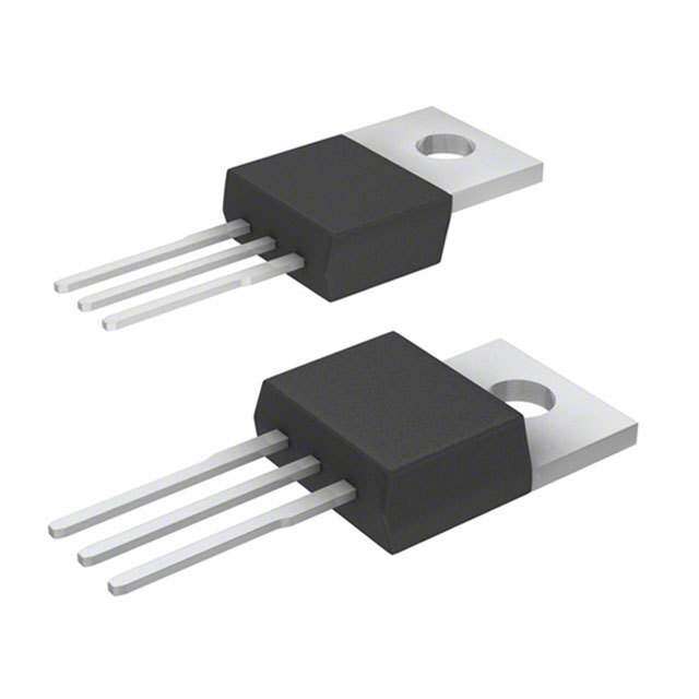
| 描述 | TRANSISTOR NPN 8A 100V TO-220 |
| 产品分类 | 晶体管(BJT) - 单路 |
| 品牌 | Micro Commercial Co |
| 数据手册 | |
| 产品图片 |
|
| 产品型号 | TIP102-BP |
| rohs | 无铅 / 符合限制有害物质指令(RoHS)规范要求 |
| 产品系列 | - |
| 不同 Ib、Ic时的 Vce饱和值(最大值) | 2.5V @ 80mA,8A |
| 不同 Ic、Vce 时的DC电流增益(hFE)(最小值) | 1000 @ 3A,4V |
| 产品培训模块 | http://www.digikey.cn/PTM/IndividualPTM.page?site=cn&lang=zhs&ptm=24932 |
| 产品目录绘图 |
|
| 产品目录页面 | |
| 供应商器件封装 | TO-220 |
| 其它名称 | TIP102BP |
| 其它图纸 |
|
| 功率-最大值 | 80W |
| 包装 | 管件 |
| 安装类型 | 通孔 |
| 封装/外壳 | TO-220-3 |
| 晶体管类型 | NPN - 达林顿 |
| 标准包装 | 1,000 |
| 电压-集射极击穿(最大值) | 100V |
| 电流-集电极(Ic)(最大值) | 8A |
| 电流-集电极截止(最大值) | 50µA |
| 频率-跃迁 | - |


PDF Datasheet 数据手册内容提取
M C C TIP100 (cid:1)(cid:2)(cid:3)(cid:4)(cid:5)(cid:6)(cid:7)(cid:5)(cid:8)(cid:8)(cid:9)(cid:4)(cid:3)(cid:2)(cid:10)(cid:11)(cid:6)(cid:7)omponents TM 20736 Marilla Street Chatsworth Micro Commercial Components TIP101 (cid:7)(cid:12)(cid:6)(cid:13)(cid:14)(cid:15)(cid:14)(cid:14) (cid:16)(cid:17)(cid:5)(cid:18)(cid:9)(cid:19)(cid:6)(cid:20)(cid:21)(cid:14)(cid:21)(cid:22)(cid:6)(cid:23)(cid:24)(cid:14)(cid:25)(cid:26)(cid:13)(cid:15)(cid:15) TIP102 (cid:27)(cid:10)(cid:28)(cid:19)(cid:6)(cid:6)(cid:6)(cid:20)(cid:21)(cid:14)(cid:21)(cid:22)(cid:6)(cid:23)(cid:24)(cid:14)(cid:25)(cid:26)(cid:13)(cid:15)(cid:13) Features • Mounting Torgue: 5 in-lbs Maximum • Lead Free Finish/RoHS Compliant(Note 1) ("P" Suffix designates RoHS Compliant. See ordering information) • High DC Current Gain : h =2500 (Typ) @ I =4.0Adc NPN Plastic FE C • Halogen free available upon request by adding suffix "-HF" Medium-Power • Low Collector-Emitter Saturation Voltage • Monolithic Construction with Built-in Base-Emitter Shunt Resistors • TO-220 Compact package Silicon Transistors • Epoxy meets UL 94 V-0 flammability rating • Moisure Sensitivity Level 1 Maximum Ratings Symbol Parameter Rating Unit TO-220 V Collector-Emitter Voltage CEO 60 TIP100 80 V TIP101 100 B C TIP102 V Collector-Base Voltage TIP100 60 F S CBO TIP101 80 V TIP102 100 Q VEBO Emitter-Base Voltage 5.0 V T I Collector Current-continuous 8.0 A C I Collector Current-peak 15 A A CP IB Base Current 1.0 A U Collector Dissipation @T =25OC 80 W PD Derate above 25 OC C 0.64 W/OC 1 2 3 TJ, Junction Temperature -55 to +150 OC H T Storage Temperature -55 to +150 OC STG Electrical Characteristics @ 25OC Unless Otherwise Specified K Symbol Parameter Min Max Units OFF CHARACTERISTICS V Collector-Emitter Sustaining Voltage V CEO(SUS) L J (I =30mAdc,I =0) TIP100 60 --- C B D TIP101 80 --- Vdc R G TIP101 100 --- N I Collector Cut-off Current CEO (V =30Vdc, I =0) TIP100 --- 50 (VCE=40Vdc, IB=0) TIP101 --- 50 µAdc PIN 1. BASE CE B PIN 2. COLLECTOR (VCE=50Vdc,IB=0) TIP102 --- 50 PIN 3. EMITTER I Collector Cut-off Current CBO (V =60Vdc, I =0) TIP100 --- 50 CB E µAdc (V =80Vdc, I =0) TIP101 --- 50 CB E (V =100Vdc,I =0) TIP102 --- 50 CB E I Emitter Cut-off Current EBO DIMENSIONS (V =5.0Vdc, I =0) --- 8.0 mAdc BE C INCHES MM ON CHARACTERISTICS(1) DIM MIN MAX MIN MAX NOTE A .560 .625 14.22 15.88 hFE(1) DC Current Gain B .380 .420 9.65 10.67 (IC=3.0Adc, VCE=4.0Vdc) 1000 20000 ---- C .140 .190 3.56 4.82 (IC=8.0Adc, VCE=4.0Vdc) 200 --- D .020 .045 0.51 1.14 VCE(sat) Collector-Emitter Saturation Voltage F .139 .161 3.53 4.09 ∅ (IC=3.0Adc, IB=6.0mAdc) --- 2.0 G .190 .110 2.29 2.79 (I =8.0Adc, I =80mAdc) --- 2.5 Vdc H --- .250 --- 6.35 C B V Base-Emitter On Voltage J .012 .025 0.30 0.64 BE(ON) (I =8.0Adc,V =4.0Adc) --- 2.8 Vdc K .500 .580 12.70 14.73 C CE L .045 .060 1.14 1.52 hfe Small-Signal Current Gain N .190 .210 4.83 5.33 (I =3.0Adc,V =4.0Vdc,f=1.0MHz) 4.0 --- --- C CE Q .100 .135 2.54 3.43 C Output Capacitance ob R .080 .115 2.04 2.92 (VCB=10V, IE=0, f=0.1MHz) --- 200 pF S .045 .055 1.14 1.39 (1)Pulse Test: Pulse Width<300us,DutyCycle<2% T .230 .270 5.84 6.86 U ----- .050 ----- 1.27 Notes:1.High Temperature Solder Exemption Applied, see EU Directive Annex 7. V .045 ----- 1.15 ----- www.mccsemi.com 1 of 4 Revision: C 2013/01/01
TIP100,101,102 M C C ÎÎÎÎÎÎÎÎÎÎÎÎÎÎ ÎÎÎÎÎÎÎÎÎÎÎÎÎÎ TM Micro Commercial Components TA TC 5.0 4.0 80 3.0 ts S) 2.0 T T A 3.0 60 W tf N ( 1.0 SSIPATIO 2.0 40 TC µTIME (s) 00..57 DI t, 0.3 WER 0.2 VCC = 30 V tr , POD1.0 20 TA 0.1 IICB1/I B= =IB 2250 P 0.07 TJ = 25°C td @ VBE(off) = 0 V 0 0 0.05 0.1 0.2 0.3 0.5 0.7 1.0 2.0 3.0 5.0 7.0 10 0 20 40 60 80 100 120 140 160 T, TEMPERATURE (°C) IC, COLLECTOR CURRENT (AMP) Figure2. Switching Times Figure 1. Power Derating 1.0 E 0.7 C D = 0.5 N 0.5 A T S ESI 0.3 0.2 L RD) 0.2 MAZE 0.1 T THERORMALI 00.0.17 0.05 ZRθθJJCC( t=) =1 .r5(6t)° RCθ/WJC MAX P(pk) NN 0.05 D CURVES APPLY FOR POWER SIE( 0.02 PULSE TRAIN SHOWN r(t), TRAN 00..0023 0.01 SINGLE PULSE RTJE(ApkD) T– ITMCE =A TP (tp1k) ZθJC(t) DUTtY1 CtY2CLE, D = t1/t2 0.01 0.01 0.02 0.05 0.1 0.2 0.5 1.0 2.0 5.0 10 20 50 100 200 500 1.0 k t, TIME (ms) Figure3. Thermal Response 20 10 5ms mA) 5.0 100µs T ( URREN 21..00 BTOJ N=D 1I5N0G°C WIRE LIMITE1Dms dc C R 0.5 THERMALLY LIMITED @ TC = 25°C O CT SECOND BREAKDOWN LIMITED LE 0.2 CURVES APPLY BELOW RATED VCEO L O C 0.1 , C TIP100 I 0.05 TIP101 TIP102 0.02 1.0 2.0 5.0 10 20 50 100 VCE, COLLECTOR–EMITTER VOLTAGE (VOLTS) Figure 4. Active–Region Safe Operating Area www.mccsemi.com 2 of 4 Revision: C 2013/01/01
TIP100,101,102 M C C TM Micro Commercial Components 10,000 300 N 5000 TC = 25°C TJ = 25°C GAI 3000 VCE = 4.0 Vdc 200 T 2000 IC = 3.0 Adc RREN 1000 E (pF) Cob U C C 500 N GNAL 320000 ACITA 100 Cib L–SI 100 CAP 70 AL C, SM 50 50 , e 30 hf 20 10 30 1.0 2.0 5.0 10 20 50 100 200 500 1000 0.1 0.2 0.5 1.0 2.0 5.0 10 20 50 100 f, FREQUENCY (kHz) VR, REVERSE VOLTAGE (VOLTS) Figure 5. Small–Signal Current Gain Figure 6. Capacitance 20,000 S) 3.0 T VCE = 4.0 V VOL TJ = 25°C 10,000 GE ( 2.6 GAIN 5000 TJ = 150°C OLTA ENT 3000 25°C ER V 2.2 IC = 2.0 A 4.0 A 6.0 A R T R 2000 T U MI C C –55°C –E 1.8 , DE1000 TOR F C h E 500 L 1.4 L O C 300 , E 200 VC 1.0 0.1 0.2 0.3 0.5 0.7 1.0 2.0 3.0 10 0.3 0.5 0.7 1.0 2.0 5.0 10 20 30 IC, COLLECTOR CURRENT (AMP) IB, BASE CURRENT (mA) Figure7. DC Current Gain Figure8. Collector Saturation Region 3.0 TJ = 25°C 2.5 S) T L O V 2.0 E ( G A OLT 1.5 VBE(sat) @ IC/IB = 250 V V, VBE @ VCE = 4.0 V 1.0 VCE(sat) @ IC/IB = 250 0.5 0.1 0.2 0.3 0.5 0.7 1.0 2.0 3.0 5.0 7.0 10 IC, COLLECTOR CURRENT (AMP) Figure 9. “On” Voltages www.mccsemi.com 3 of 4 Revision: C 2013/01/01
M C C TM Micro Commercial Components Ordering Information : Device Packing Part Number-BP Bulk;1Kpcs/Box Note : Adding "-HF" suffix for halogen free, eg. Part Number-BP-HF ***IMPORTANT NOTICE*** Micro Commercial Components Corp.r eserves the right to make changes without further notice to any product herein to make corrections, modifications , enhancements , improvements , or other changes . Micro Commercial Components Corp . does not assume any liability arising out of the application or use of any product described herein; neither does it convey any license under its patent rights ,nor the rights of others . The user of products in such applications shall assume all risks of such use and will agree to holdM icro Commercial Components Corp .a nd all the companies whose products are represented on our website, harmless against all damages . ***LIFE SUPPORT*** MCC's products are not authorized for use as critical components in life support devices or systems without the express written approval of Micro Commercial Components Corporation . ***CUSTOMER AWARENESS*** Counterfeiting of semiconductor parts is a growing problem in the industry. Micro Commercial Components (MCC) is taking strong measures to protect ourselves and our customers from the proliferation of counterfeit parts. MCC strongly encourages customers to purchase MCC parts either directly from MCC or from Authorized MCC Distributors who are listed by country on our web page cited below. Products customers buy either from MCC directly or from Authorized MCC Distributors are genuine parts, have full traceability, meet MCC's quality standards for handling and storage.M CC will not provide any warranty coverage or other assistance for parts bought from Unauthorized Sources .MCC is committed to combat this global problem and encourage our customers to do their part in stopping this practice by buying direct or from authorized distributors. www.mccsemi.com 4 of 4 Revision: C 2013/01/01