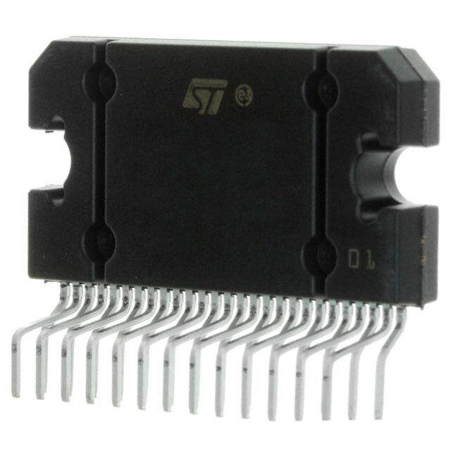
ICGOO在线商城 > 集成电路(IC) > 线性 - 音頻放大器 > TDA7496
- 型号: TDA7496
- 制造商: STMicroelectronics
- 库位|库存: xxxx|xxxx
- 要求:
| 数量阶梯 | 香港交货 | 国内含税 |
| +xxxx | $xxxx | ¥xxxx |
查看当月历史价格
查看今年历史价格
TDA7496产品简介:
ICGOO电子元器件商城为您提供TDA7496由STMicroelectronics设计生产,在icgoo商城现货销售,并且可以通过原厂、代理商等渠道进行代购。 TDA7496价格参考。STMicroelectronicsTDA7496封装/规格:线性 - 音頻放大器, Amplifier IC 2-Channel (Stereo) Class AB 15-Multiwatt。您可以下载TDA7496参考资料、Datasheet数据手册功能说明书,资料中有TDA7496 详细功能的应用电路图电压和使用方法及教程。
| 参数 | 数值 |
| 产品目录 | 集成电路 (IC)半导体 |
| 描述 | IC AMP PWR AB 5+5W MULTIWATT15音频放大器 5W DC Amp w/Col Cont |
| 产品分类 | |
| 品牌 | STMicroelectronics |
| 产品手册 | |
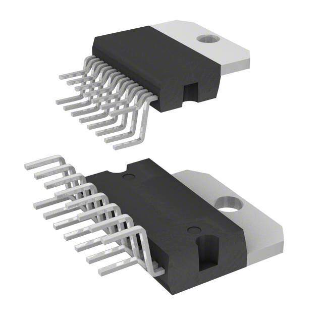
| 产品图片 |
|
| rohs | 符合RoHS无铅 / 符合限制有害物质指令(RoHS)规范要求 |
| 产品系列 | 音频 IC,音频放大器,STMicroelectronics TDA7496- |
| 数据手册 | |
| 产品型号 | TDA7496 |
| Pd-功率耗散 | 15000 mW |
| THD+噪声 | 0.4 % |
| 不同负载时的最大输出功率x通道数 | 5.5W x 2 @ 8 欧姆 |
| 产品 | Audio Amplifiers |
| 产品目录页面 | |
| 产品种类 | 音频放大器 |
| 供应商器件封装 | 15-Multiwatt |
| 其它名称 | 497-8872-5 |
| 其它有关文件 | http://www.st.com/web/catalog/sense_power/FM125/CL1503/SC979/PF65245?referrer=70071840 |
| 包装 | 管件 |
| 商标 | STMicroelectronics |
| 增益 | 30 dB |
| 安装类型 | 通孔 |
| 安装风格 | Through Hole |
| 封装 | Tube |
| 封装/外壳 | Multiwatt-15(垂直,弯曲和错列引线) |
| 封装/箱体 | Multiwatt-15 |
| 工作温度 | 0°C ~ 70°C (TA) |
| 工作电源电压 | 12 V, 15 V, 18 V, 24 V, 28 V |
| 工厂包装数量 | 25 |
| 最大功率耗散 | 15000 mW |
| 最大工作温度 | + 70 C |
| 最小工作温度 | 0 C |
| 标准包装 | 25 |
| 特性 | 消除爆音,静音,短路和热保护,待机,音量控制 |
| 电压-电源 | 10 V ~ 32 V |
| 电源电压-最大 | 32 V |
| 电源电压-最小 | 10 V |
| 电源类型 | Single |
| 类 | Class-AB |
| 类型 | 2-Channel Stereo |
| 系列 | TDA7496 |
| 输入信号类型 | Single |
| 输出信号类型 | Single |
| 输出功率 | 5.5 W |
| 输出类型 | 2 通道(立体声) |
| 音频负载电阻 | 8 Ohms |


- 商务部:美国ITC正式对集成电路等产品启动337调查
- 曝三星4nm工艺存在良率问题 高通将骁龙8 Gen1或转产台积电
- 太阳诱电将投资9.5亿元在常州建新厂生产MLCC 预计2023年完工
- 英特尔发布欧洲新工厂建设计划 深化IDM 2.0 战略
- 台积电先进制程称霸业界 有大客户加持明年业绩稳了
- 达到5530亿美元!SIA预计今年全球半导体销售额将创下新高
- 英特尔拟将自动驾驶子公司Mobileye上市 估值或超500亿美元
- 三星加码芯片和SET,合并消费电子和移动部门,撤换高东真等 CEO
- 三星电子宣布重大人事变动 还合并消费电子和移动部门
- 海关总署:前11个月进口集成电路产品价值2.52万亿元 增长14.8%




PDF Datasheet 数据手册内容提取
TDA7496 5W+5W AMPLIFIER WITH DC VOLUME CONTROL n 5+5W OUTPUT POWER RL = 8W @THD = 10% VCC = 22V MULTIPOWER BI50II TECHNOLOGY n ST-BY AND MUTE FUNCTIONS n LOW TURN-ON TURN-OFF POP NOISE n LINEAR VOLUME CONTROL DC COUPLED WITH POWER OP. AMP. n NO BOUCHEROT CELL n NO ST_BY RC INPUT NETWORK Multiwatt 15 n SINGLE SUPPLY RANGING UP TO 35V ORDERING NUMBER: TDA7496 n SHORT CIRCUIT PROTECTION n THERMAL OVERLOAD PROTECTION n INTERNALLY FIXED GAIN n SOFT CLIPPING plifier assembled i the @ Multiwatt 15 package, spe- n VARIABLE OUTPUT AFTER VOLUME cially designed for high quality sound, TV applications. CONTROL CIRCUIT Features of the TDA7496 include linear volume con- n MULTIWATT 15 PACKAGE trol Stand-by and Mute functions. The TDA7496 is pin to pin compatible with DESCRIPTION TDA7496S, TDA7496SA, TDA7495, TDA7495SA, The TDA7496 is a stereo 5+5W class AB power am- TDA7494S, TDA7494SA. BLOCK DIAGRAM VAROUT_R VS 214 13 PW_GND PW_GND 11 15 VOLUME 1 1000m F INR + 470nF 30K 9 - OUTR OP AMP S1 ST-BY 10 +5V S_GND STBY 8 MUTE/STBY 10K S_GND P12ROTECTIONS MUTE 60K 1m F +5V VOLUME S2 MUTE 5 INL + OUTL 470nF 30K - 1000m F OP AMP SVR 7 470m F 3 4 VOLUME VAROUT_L +5V 300K 100nF D96AU440D September 2003 1/11
TDA7496 ABSOLUTE MAXIMUM RATINGS Symbol Parameter Value Unit VS DC Supply Voltage 35 V VIN Maximum Input Voltage 8 Vpp Ptot Total Power Dissipation (Tamb = 80°C) 15 W Tamb Ambient Operating Temperature (1) 0 to 70 °C Tstg,TJ Storage and Junction Temperature -40 to 150 °C V3 Volume Control DC Voltage 7 V PIN CONNECTION (top view) 15 PW_GND 14 OUTR 13 VS 12 OUTL 11 PW_GND 10 MUTE 9 STBY 8 S_GND 7 SVR 6 N.C. 5 INL 4 VAROUT_L 3 VOLUME 2 VAROUT_R 1 INR D96AU441B THERMAL DATA Symbol Parameter Value Unit Rth j-case Thermal Resistance junction-case Typ. = 4; Max. = 4.6 °C/W Rth j-amb Thermal Resistance junction-ambient Max. 35 °C/W ELECTRICAL CHARACTERISTCS (Refer to the test circuit V = 22V; R = 8W , R = 50W , T = 25°C) s L g amb Symbol Parameter Test Condition Min. Typ. Max. Unit Vs Supply Voltage Range 10 32 V Iq Total Quiescent Current 25 50 mA DCVos Output DC Offset Referred to SVR No Input Signal 200 mV Potential VO Quiescent Output Voltage 11 V PO Output Power THD = 10%; RL = 8W ; 5 5.5 W THD = 1%; RL = 8W ; 4 THD = 10%; RL = 4W ; VS = 12V 2.1 W THD = 1%; RL = 4W ; VS = 12V 1.0 THD Total Harmonic Distortion Gv = 30dB; PO = 1W; f = 1KHz 0.4 % 2/11
TDA7496 ELECTRICAL CHARACTERISTCS (continued) (Refer to the test circuit Vs = 22V; RL = 8W , Rg = 50W , Tamb = 25°C) Symbol Parameter Test Condition Min. Typ. Max. Unit Ipeak Output Peak Current (internally limited) 1.0 1.3 A VIN Input Signal 2.8 Vrms GV Closed Loop Gain VOl Ctrl >4.5V 28.5 30 31.5 dB GVLine Monitor Out Gain VOl Ctrl >4.5V; Zload >30KW -1.5 0 1.5 dB AMin VOL Attenuation at Minimum Volume VOl Ctrl <0.5V 80 dB BW 0.6 MHz eN Total Output Noise f = 20Hz to 22KHz 500 800 m V PLAY, max volume f = 20Hz to 22KHz 100 250 m V PLAY, max attenuation f = 20Hz to 22KHz MUTE 60 150 m V SR Slew Rate 5 8 V/m s Ri Input Resistance 22.5 30 KW RVar Out Variable Output Resistance 30 100 W RL Var Out Variable Output Load 2 KW SVR Supply Voltage Rejection f = 1KHz; max volume 35 39 dB CSVR = 470m F; VRIP = 1Vrms f = 1KHz; max attenuation 55 65 dB CSVR = 470m F; VRIP = 1Vrms TM Thermal Muting 150 °C TS Thermal Shut-down 160 °C MUTE & INPUT SELECTION FUNCTIONS VST-ON Stand-by ON Threshold 3.5 V VST-OFF Stand-by OFF Threshold 1.5 V VMUTEON Mute ON threshold 3.5 V VMUTEOFF Mute OFF threshold 1.5 V AMUTE Mute Attenuation 50 65 dB IqST-BY Quiescent Current @ Stand-by 0.6 1 mA IstbyBIAS Stand-by bias current Stand by ON: VST-BY = 5V; 80 m A Vmute = 5V Play or Mute -20 -5 m A ImuteBIAS Mute Bias Current Mute 1 5 m A Play 0.2 2 m A 3/11
TDA7496 APPLICATION SUGGESTIONS The recommended values of the external components are those shown on the application circuit of figure 1. Different values can be used, the following table can help the designer. SUGGESTION LARGER THAN SMALLER THAN COMPONENT PURPOSE VALUE SUGGESTION SUGGESTION R1 300K Volume Control Circuit Larger volume regulation Smaller volume regulation time time R2 10K Mute time constant Larger mute on/off time Smaller mute on/off time P1 50K Volume Control Circuit C1 1000m F Supply voltage bypass Danger of oscillation C2 470nF Input DC decoupling Lower low frequency cutoff Higher low frequency cutoff C3 470nF Input DC decoupling Lower low frequency cutoff Higher low frequency cutoff C4 470m F Ripple rejection Better SVR Worse SVR C5 100nF Volume control time Larger volume regulation Smaller volume regulation constant time time C6 1000m F Output DC decoupling Lower low frequency cutoff Higher low frequency cutoff C7 1m F Mute time constant Larger mute on/off time Smaller mute on/off time C8 1000m F Output DC decoupling Lower low frequency cutoff Higher low frequency cutoff C9 100nF Supply voltage bypass Danger of oscillation Figure 1. Application Circui +VS C1 C9 1000m F 0.1m F VAROUT_R VS 2 13 PW_GND PW_GND 11 15 VOLUME 1 C8 1000m F PW_GND INR + 14 OUTR C2 470nF 30K - OP AMP S1 STBY +5V S_GND 9 8 MUTE/STBY 10 R2 10K S_GND PROTECTIONS VOLUME C7 +5V 1m F S2 MUTE 5 INL + 12 OUTL C3 470nF 30K - C6 1000m F PW_GND OP AMP SVR 7 C4 470m F 3 4 VOLUME VAROUT_L +5V VOL P1 C5 R1 300K 50K D96AU493D 100nF LOG TP1 4/11
TDA7496 MUTE STAND-BY TRUTH TABLE MUTE St-BY OPERATING CONDITION H H STAND-BY L H STAND-BY H L MUTE L L PLAY Turn ON/OFF Sequences (for optimizing the POP performances) Figure 1. USING ONLY THE MUTE FUNCTION VS (V) ST-BY pin#9 (V) 5 VSVR pin#7(V) 2.5V MUTE pin#10 (V) 5 INPUT (mV) VOUT (V) OFF STBY MUTE PLAY MUTE STBY OFF IQ (mA) D97AU684 USING ONLY THE MUTE FUNCTION To semplify the application, the stand-by pin can be connected directly to Ground. During the ON/OFF transi- tions is recommended to respect the following conditions: – At the turn-on the transition mute to mute - play must be made when the SVR pin is higher than 2.5V – At the turn-off the TDA7496 must be brought to mute from the play condition when the SVR pin is higher than 2.5V. 5/11
TDA7496 Figure 2. P.C.B. and Component layoutPCB and Component Layout Figure 3. 6/11
TDA7496 Figure 4. Quiescent Current vs. Supply Voltage Figure 7. Output DC Offset vs. Supply Voltage Iq Vodc-Vsvr D03AU1494 D03AU1496 (mA) (V) 30 280 Vi=0 260 Vi=0 28 240 26 220 24 200 180 22 160 20 140 18 120 16 100 10 12 14 16 18 20 22 24 26 28 30 32 10 12 14 16 18 20 22 24 26 28 30 32 Supply Voltage (V) Supply Voltage (V) Figure 8. Output Power vs Supply Voltage Figure 5. Output Dc Offset vs. Supply Voltage Output Power D03AU1498 Vodc D03AU1495 (W) (V) 3.2 1156 Vi=0 2.8 Rl=4W F=1KHz 14 2.4 13 THD=10% 12 2.0 11 1.6 10 9 1.2 8 THD=1% 7 0.8 6 0.4 5 4 0 10 12 14 16 18 20 22 24 26 28 30 32 10 10.5 11 11.5 12 12.5 13 13.5 14 Supply Voltage (V) Supply Voltage (V) Figure 6. Output Power vs. Supply Voltage Figure 9. Distortion vs Output Power Output Power D03AU1497 Distortion D03AU1499 (W) (%) Rl=8W 8 Vs=22V F=1KHz 7 1 Rl=8W THD=10% 6 5 F=15KHz 4 0.1 3 THD=1% 2 F=1KHz 1 0 0.01 10 12 14 16 18 20 22 24 26 0 0.5 1.0 1.5 2.0 2.5 3.0 3.5 4.0 4.5 5.0 5.5 Supply Voltage (V) Output Power (W) 7/11
TDA7496 Figure 10. Distortion vs Output Power Figure 13. Mute Attenuation vs Vpin 10 Distortion D03AU1500 (%) Mute Attenuation D03AU1503 (dB) 0 1 F=15KHz -20 Rl=8W -40 0dB @ Pout=1W Vs=12V Rl=4W -60 0.1 -80 F=1KHz -100 -120 0.01 0 0.4 0.8 1.2 1.6 2.0 2.4 2.8 3.2 3.6 4.0 4.4 4.8 5.2 0 0.2 0.4 0.6 0.8 1.0 1.2 1.4 1.6 1.8 2.0 Vpin # 10 (V) Output Power (W) Figure 11. Closed Loop Gain vs. Frequency PINS DESCRIPTION Figure 14. PIN SVR Closed loop D03AU1501 Gain (dB) 30 VS VS VS 28 Rl=8W Pout=0.5W + OUT L 26 Cin=470nF - Cout=1000m F 24 Csvr=470m F 20K 6K 1K 30K SVR 22 20K 6K 1K 20 30K 0.02 0.2 2 20 - OUT R Frequency (KHz) + 100m A Figure 12. St-By Attenuation vs Vpin 9 D97AU585A Figure 15. PINS: INL,INR St-by Attenuation D03AU1502 (dB) 0 VS -20 -40 Rl=8W 6K 500m A 0dB @ Pout=1W -60 INn -80 30K -100 -120 D97AU589 SVR -140 0 0.5 1.0 1.5 2.0 2.5 3.0 3.5 4.0 4.5 5.0 Vpin # 9 (V) 8/11
TDA7496 Figure 17. PIN ST-BY Figure 20. PINS: VAROUT-L VAROUT-R VS V S 10m A STBY 200 VAROUT-L 65K D97AU594 D97AU590 Figure 18. PIN: MUTE Figure 21. PIN: VOLUME V S V MUTE 200 10K S 50m A 10m A D97AU592 VOL Figure 19. PINS: OUT R, OUT L D97AU591 VS Figure 22. PINS: PW-GND, S-GND OUT V S GND D97AU593 D97AU588 9/11
TDA7496 mm inch DIM. OUTLINE AND MIN. TYP. MAX. MIN. TYP. MAX. MECHANICAL DATA A 5 0.197 B 2.65 0.104 C 1.6 0.063 D 1 0.039 E 0.49 0.55 0.019 0.022 F 0.66 0.75 0.026 0.030 G 1.02 1.27 1.52 0.040 0.050 0.060 G1 17.53 17.78 18.03 0.690 0.700 0.710 H1 19.6 0.772 H2 20.2 0.795 L 21.9 22.2 22.5 0.862 0.874 0.886 L1 21.7 22.1 22.5 0.854 0.870 0.886 L2 17.65 18.1 0.695 0.713 L3 17.25 17.5 17.75 0.679 0.689 0.699 L4 10.3 10.7 10.9 0.406 0.421 0.429 L7 2.65 2.9 0.104 0.114 M 4.25 4.55 4.85 0.167 0.179 0.191 M1 4.63 5.08 5.53 0.182 0.200 0.218 S 1.9 2.6 0.075 0.102 Multiwatt15 V S1 1.9 2.6 0.075 0.102 Dia1 3.65 3.85 0.144 0.152 10/11
TDA7496 Information furnished is believed to be accurate and reliable. However, STMicroelectronics assumes no responsibility for the consequences of use of such information nor for any infringement of patents or other rights of third parties which may result from its use. No license is granted by implication or otherwise under any patent or patent rights of STMicroelectronics. Specifications mentioned in this publication are subject to change without notice. This publication supersedes and replaces all information previously supplied. STMicroelectronics products are not authorized for use as critical components in life support devices or systems without express written approval of STMicroelectronics. The ST logo is a registered trademark of STMicroelectronics. All other names are the property of their respective owners © 2003 STMicroelectronics - All rights reserved STMicroelectronics GROUP OF COMPANIES Australia - Belgium - Brazil - Canada - China - Czech Republic - Finland - France - Germany - Hong Kong - India - Israel - Italy - Japan - Malaysia - Malta - Morocco - Singapore - Spain - Sweden - Switzerland - United Kingdom - United States www.st.com 11/11
Mouser Electronics Authorized Distributor Click to View Pricing, Inventory, Delivery & Lifecycle Information: S TMicroelectronics: TDA7496
 Datasheet下载

