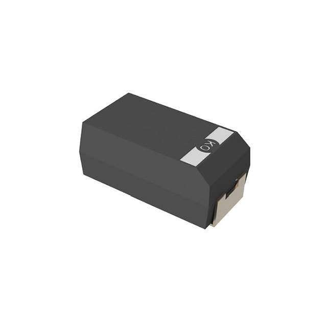
ICGOO在线商城 > 电容器 > 钽 - 聚合物电容器 > TCNL157M006R0200
- 型号: TCNL157M006R0200
- 制造商: AVX
- 库位|库存: xxxx|xxxx
- 要求:
| 数量阶梯 | 香港交货 | 国内含税 |
| +xxxx | $xxxx | ¥xxxx |
查看当月历史价格
查看今年历史价格
TCNL157M006R0200产品简介:
ICGOO电子元器件商城为您提供TCNL157M006R0200由AVX设计生产,在icgoo商城现货销售,并且可以通过原厂、代理商等渠道进行代购。 TCNL157M006R0200价格参考。AVXTCNL157M006R0200封装/规格:钽 - 聚合物电容器, 150µF 模制 聚合物钽电容器 6.3V 1411(3528 公制),1210 200 毫欧。您可以下载TCNL157M006R0200参考资料、Datasheet数据手册功能说明书,资料中有TCNL157M006R0200 详细功能的应用电路图电压和使用方法及教程。
| 参数 | 数值 |
| 产品目录 | |
| 描述 | CAP TANT 150UF 6.3V 20% 1210钽质电容器-SMD聚合物 6.3volts 150uF 20% |
| ESR | 200 mOhms |
| ESR(等效串联电阻) | 200 毫欧 |
| 产品分类 | |
| 品牌 | AVX |
| 产品手册 | |
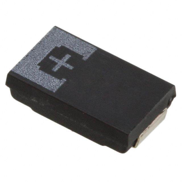
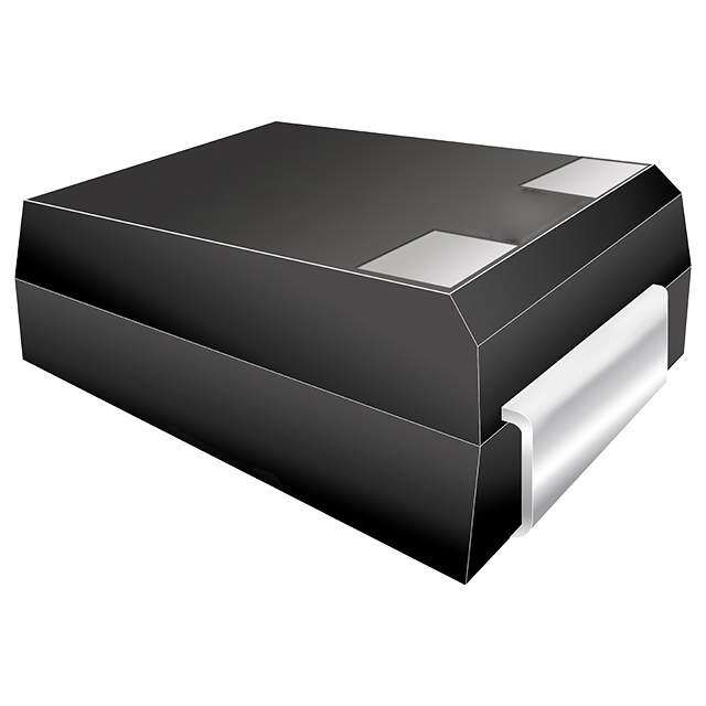
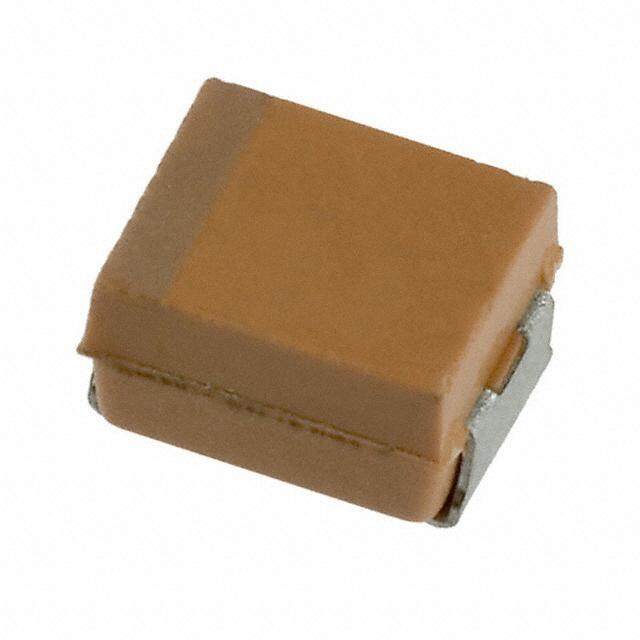
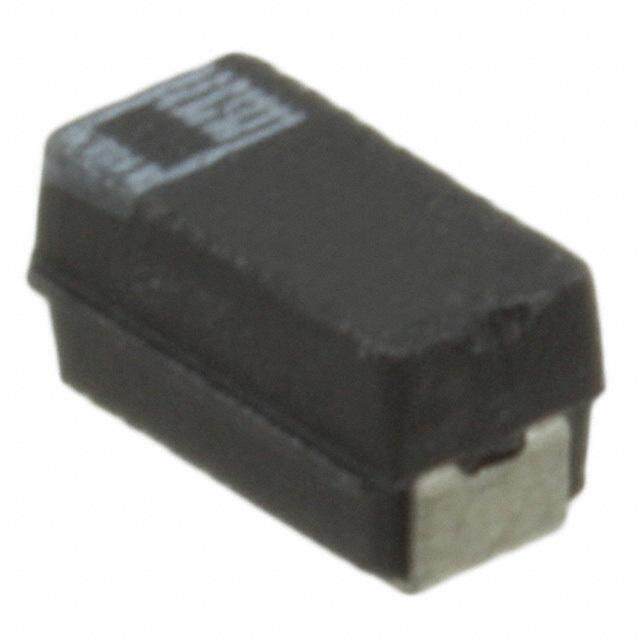
| 产品图片 |
|
| rohs | 符合RoHS无铅 / 符合限制有害物质指令(RoHS)规范要求 |
| 产品系列 | 高分子电容器,钽质电容器-SMD聚合物,AVX TCNL157M006R0200TCN |
| 数据手册 | |
| 产品型号 | TCNL157M006R0200 |
| 不同温度时的使用寿命 | - |
| 产品 | Tantalum Organic Polymer Low ESR |
| 产品培训模块 | http://www.digikey.cn/PTM/IndividualPTM.page?site=cn&lang=zhs&ptm=21795 |
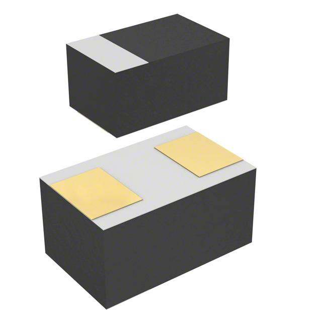
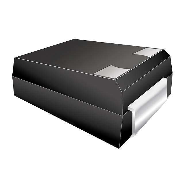
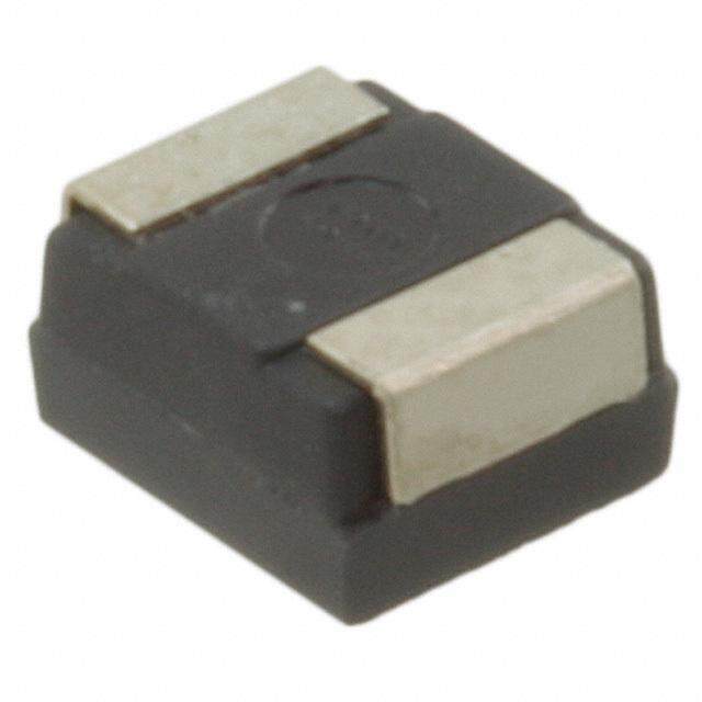
| 产品目录绘图 |
|
| 产品目录页面 | |
| 产品种类 | 钽质电容器-SMD聚合物 |
| 其它名称 | 478-5527-1 |
| 制造商尺寸代码 | L |
| 制造商库存号 | L Case |
| 包装 | 剪切带 (CT) |
| 商标 | AVX |
| 外壳代码-in | 1210 |
| 外壳代码-mm | 3528 |
| 外壳宽度 | 2.8 mm |
| 外壳长度 | 3.5 mm |
| 大小/尺寸 | 0.138" 长 x 0.110" 宽(3.50mm x 2.80mm) |
| 安装类型 | 表面贴装 |
| 容差 | 20 % |
| 封装 | Reel |
| 封装/外壳 | 1210(3528 公制) |
| 封装/箱体 | 1210 (3528 metric) |
| 工作温度 | -55°C ~ 105°C |
| 工作温度范围 | - 55 C to + 105 C |
| 工厂包装数量 | 2500 |
| 引线间距 | - |
| 损耗因数DF | 10 % |
| 标准包装 | 1 |
| 特性 | 聚合物 |
| 电压-额定 | 6.3V |
| 电压额定值 | 6.3 V |
| 电压额定值DC | 6.3 V |
| 电容 | 150 uF |
| 端接类型 | SMD/SMT |
| 类型 | Tantalum Solid Electrolytic Chip Capacitors Undertab |
| 系列 | TCN |
| 高度 | 1 mm |
| 高度-安装(最大值) | 0.039"(1.00mm) |
PDF Datasheet 数据手册内容提取
TCN Series Highest CV/cc Conductive Polymer Chip Capacitors Undertab FEATURES • Highest CV/cc in broad range of low profiles • Conductive polymer electrode • Benign failure mode under recommended use conditions • Lower ESR LEAD-FREE COMPATIBLE COMPONENT • Undertab terminations layout: - High Volumetric Efficiency - High PCB assembly density - High capacitance in smaller dimensions • 3x reflow 260°C compatible • 10 case sizes available APPLICATIONS • Consumer applications (e.g. mobiles, MP3 etc.) • Bulk decoupling of SoC (System on chip) Polarity Band (Anode+) Polarity Band (Anode+) W L W W L W H H WP AP S AN WN WP AP S AN WN CASE DIMENSIONS:millimeters (inches) EIA EIA L±0.20 W+0.20 (0.008) W±0.10 W±0.10 A±0.10 A±0.10 Code H max. P N P N S Min. Code Metric (0.008) -0.10 (0.004) (0.004) (0.004) (0.004) (0.004) M 0805 2012-09 2.05 (0.081) 1.30 (0.051) 0.90 (0.035) 1.00 (0.039) 1.00 (0.039) 0.85 (0.033) 0.85 (0.033) 0.40 (0.016) N 0805 2012-10 2.05 (0.081) 1.30 (0.051) 1.00 (0.039) 1.00 (0.039) 1.00 (0.039) 0.85 (0.033) 0.85 (0.033) 0.40 (0.016) O 1206 3216-06 3.20 (0.126) 1.60 (0.063) 0.60 (0.024) 1.30 (0.051) 1.30 (0.051) 1.15 (0.045) 1.15 (0.045) 0.90 (0.035) K 1206 3216-10 3.20 (0.126) 1.60 (0.063) 1.00 (0.039) 1.30 (0.051) 1.30 (0.051) 1.15 (0.045) 1.15 (0.045) 0.90 (0.035) S 1206 3216-12 3.20 (0.126) 1.60 (0.063) 1.20 (0.047) 1.30 (0.051) 1.30 (0.051) 1.15 (0.045) 1.15 (0.045) 0.90 (0.035) L 1210 3528-10 3.50 (0.138) 2.80 (0.110) 1.00 (0.039) 2.50 (0.098) 2.10 (0.083) 1.15 (0.045) 1.35 (0.053) 1.00 (0.039) T 1210 3528-12 3.50 (0.138) 2.80 (0.110) 1.20 (0.047) 2.50 (0.098) 2.10 (0.083) 1.15 (0.045) 1.35 (0.053) 1.00 (0.039) H 1210 3528-15 3.50 (0.138) 2.80 (0.110) 1.50 (0.059) 2.50 (0.098) 2.10 (0.083) 1.15 (0.045) 1.35 (0.053) 1.00 (0.039) X 2917 7343-15 7.30 (0.287) 4.30 (0.169) 1.50 (0.059) 3.25 (0.128) 3.25 (0.128) 2.00 (0.079) 3.20 (0.126) 2.10 (0.083) 4 2924 7361-20 7.30 (0.287) 6.10 (0.240) 2.00 (0.079) 4.75 (0.187) 4.75 (0.187) 2.00 (0.079) 3.20 (0.126) 2.10 (0.083) MARKING H, K, L, O, S, T, X CASE M, N CASE 4 CASE PB(Aoanlnaodrditey+) APVoXly mLOeXrGX1OX5X6 XJC15a6p a=c 1it5aIµnDFRJc eCa= toV e6dad.le3 uVVeo ilnta pgFe PB(Aoanlnaodrditey+) 1 0 J6 C10a6p a=c R1it0aatµneFcdeJ V V=oa llt6ua.eg3 Vein C poFde PB(Aoanlnaodrditey+) APVoXly mLOeXrGX1OX5X8 XJC15a8p a=c 1it5aI0nD0RJc µ eCa=F toV e6dad.le3 uVVeo ilnta pgFe AVX LOGO Polymer PB(Aoanlnaodrditey+) APVoXly mLOeXrGX3OX3X6 XEC33a6p a=c 3it3aIµnDFREc e Ca= toV e2dad5le uVVeo ilnta pgFe PB(Aoanlnaodrditey+) 475E C10a6p a=c R1it0aatµneFcdeJ V V=oa llt6ua.eg3 Vein C poFde PB(Aoanlnaodrditey+) APVoXly mLOeXrGX1OX0X7 XVC10a7p a=c 1it0aI0nDµRVc Fe Ca= toV e3dad5le uVVeo ilnta pgFe AVX LOGO Polymer HOW TO ORDER TCN L 157 M 006 R 0200 E Type Case Size Capacitance Code Tolerance Rated DC Voltage Packaging ESR in mΩ Additional See table pF code: 1st two digits M = ±20% 006 = 6.3Vdc R = Pure Tin 7" Reel Character above represent significant figures, 016 = 16Vdc S = Pure Tin 13" Reel E = Black resin 3rd digit represents multiplier 020 = 20Vdc 025 = 25Vdc (number of zeros to follow) 035 = 35Vdc Part Numbers already changed to an “E” suffix will continue to be supplied with only black resin. Those Part Numbers currently produced with gold resin will eventually change to black before July, 2020. 214 090419
TCN Series Highest CV/cc Conductive Polymer Chip Capacitors Undertab TECHNICAL SPECIFICATIONS Technical Data: All technical data relate to an ambient temperature of +25°C Capacitance Range: 1.0 μF to 1500 μF Capacitance Tolerance: ±20% Leakage Current DCL: 0.1CV Rated Voltage (V ) (cid:2)+85ºC: 4 6.3 10 16 20 25 35 50 R Category Voltage (V ) (cid:2)+105ºC: 3.2 5 8 13 16 20 28 40 C Surge Voltage (V ) (cid:2)+85ºC: 5.2 8 13 21 26 33 46 65 S Surge Voltage (V ) (cid:2)+105ºC: 4 6 10 16 20 25 35 50 S Temperature Range: -55°C to +105°C Reliability: 1% per 1000 hours at 85°C, V with 0.1Ω/V series impedance 60% confidence level R NOTE:Conductive Polymer Capacitors are designed to operate within the limits of the environmental conditions specified for each series. If operated continuously at their maximum temperature and / or humidity limit, or beyond these limits, capacitors may exhibit a parametric shift in capacitance and increases in ESR. These changes may occur earlier if the specified environmental conditions are exceeded. Similarly, their normal operational time period will be significantly extended if their general duty cycle includes operation below max- imum temperature within humidity controlled environments. Careful attention should be paid to maximum temperature with associated high humidity environments as well as voltage derating, ripple current and current surges. Please reference the AVX Conductive Polymer Capacitor Guidelines for more information or contact factory for application assistance. CAPACITANCE AND RATED VOLTAGE RANGE (LETTER DENOTES CASE SIZE) Capacitance Rated Voltage DC to 85°C / 0.66DC to 105°C μF Code 4V (G) 6.3V (J) 10V (A) 16V (C) 20V (D) 25V (E) 35V (V) 50V (T) 1.0 105 N(1500E) L(300E) 4.7 475 N(500E) T(200E) 6.8 685 O(500E) K(350E) 10 106 O(500E) O(500E) T(200E) S(350E) 15 156 O(500E) O(500E) 22 226 O(500E) O(500E) T(200E) L(200E) 33 336 T(250E) T(200E) L(250E) 47 476 M(500E) T(200) X(100E) X(150E) T(150E) 68 686 K(200E,250E) 3(70)* 3(200)* 100 107 L(200E) 4(100E) 4(100E) S(250E) L(200E) 150 157 S(250E) X(100E) 4(70E) T(200E) H(170E) 220 227 4(70E) 4(100E) 4(100E) T(200E) 330 337 4(70E) 4(100E) 470 477 X(50E) 4(100E) X(200E)/3(100)* 1000 108 4(55E) 1500 158 4(55E) Note for designers - for the highlighted ratings, higher voltage options are now available in the same case size and are recommended for new designs. Released ratings, (ESR ratings in mOhms in parentheses) *Codes under developement - subject to change Note: Voltage ratings are minimum values. AVX reserves the right to supply higher voltage ratings in the same case size, to the same reliability standards. 090419 215
TCN Series Highest CV/cc Conductive Polymer Chip Capacitors Undertab RATINGS & PART NUMBER REFERENCE Maximum ESR AVX Case Cap Rated Operating DCL DF Max. 1 0 0 k H z R M S C u r r e n t ( m A ) Product Part No. Size (μF) V o ltag e Temperature Max. Max . @ 100kHz Category MSL ( V ) (ºC) ( μ A ) ( % ) (mΩ) 45ºC 85ºC 105ºC 4 Volt @ 85°C TCNO226M004#0500E O 22 4 105 8.8 10 500 400 300 200 3 3 6.3 Volt @ 85°C TCNO156M006#0500E O 15 6.3 105 9 10 500 400 300 200 3 3 TCNO226M006#0500E O 22 6.3 105 13.2 10 500 400 300 200 3 3 TCNM476M006#0500E M 47 6.3 105 28.2 10 500 400 300 200 3 3 TCNK107M006#0200E K 100 6.3 105 60 10 200 700 500 300 3 5 TCNK107M006#0250E K 100 6.3 105 60 10 250 600 400 300 3 5 TCNL107M006#0200E L 100 6.3 105 60 10 200 700 500 300 3 5 TCNS107M006#0250E S 100 6.3 105 60 10 250 600 400 300 3 3 TCNL157M006#0200E L 150 6.3 105 90 10 200 700 500 300 3 5 TCNS157M006#0250E S 150 6.3 85 90 10 250 600 400 – 5 3 TCNT157M006#0200E T 150 6.3 105 90 10 200 700 500 300 3 4 TCNH227M006#0170E H 220 6.3 105 132 10 170 800 600 400 3 4 TCNT227M006#0200E T 220 6.3 85 132 10 200 700 500 – 5 4 TCNX477M006#0050E X 470 6.3 85 282 10 50 1900 1300 – 5 5 TCNX108M006#0200E X 1000 6.3 85 600 30 200 900 600 – 5 5 TCN3108M006#0100 3 1000 6.3 105 600 20 100 1200 840 480 3 5 TCN4108M006#0055E 4 1000 6.3 85 600 20 55 1860 1302 – 5 4 TCN4158M006#0055E 4 1500 6.3 85 900 20 55 1860 1302 – 5 4 10 Volt @ 85°C TCNO106M010#0500E O 10 10 105 10 10 500 400 300 200 3 3 TCNO156M010#0500E O 15 10 105 15 10 500 400 300 200 3 3 16 Volt @ 85°C TCNO685M016#0500E O 6.8 16 105 10.9 10 500 400 300 200 3 3 TCNO106M016#0500E O 10 16 105 16 10 500 400 300 200 3 3 TCNL336M016#0200E L 33 16 85 52.8 6 200 700 500 – 5 5 TCNT336M016#0200E T 33 16 105 52.8 6 200 700 500 300 3 4 TCNL476M016#0250E L 47 16 85 75.2 6 250 600 400 – 5 5 TCNT476M016#0150E T 47 16 105 75.2 6 150 800 600 400 3 4 TCNT476M016#0200 T 47 16 105 75.2 6 200 700 500 300 3 4 TCNX157M016#0100E X 150 16 105 240 6 100 1300 900 600 3 4 TCN4227M016#0070E 4 220 16 105 352 20 70 1650 1155 660 2 4 TCN4337M016#0070E 4 330 16 105 528 20 70 1650 1155 660 3 4 TCN4477M016#0100E 4 470 16 85 752 20 100 1380 966 – 5 4 20 Volt @ 85°C TCN4227M020#0100E 4 220 20 85 440 10 100 1380 966 – 5 4 TCN4337M020#0100E 4 330 20 85 660 20 100 1380 966 – 5 4 25 Volt @ 85°C TCNN475M025#0500E N 4.7 25 105 11.8 10 500 400 300 200 3 3 TCNK106M025#0350E K 10 25 105 25 10 350 500 400 200 3 5 TCNS106M025#0350E S 10 25 105 25 10 350 500 400 200 3 5 TCNT226M025#0200E T 22 25 105 55 6 200 700 500 300 3 4 TCNT336M025#0250E T 33 25 105 82.5 10 250 600 400 300 3 4 TCNX476M025#0100E X 47 25 105 117.5 6 100 1300 900 600 2 5 TCN3107M025#0070 3 100 25 105 250 6 70 1440 1008 576 2 5 TCN4107M025#0100E 4 100 25 105 250 6 100 1380 966 552 2 4 TCN4157M025#0070E 4 150 25 105 375 6 70 1650 1155 660 2 4 TCN4227M025#0100E 4 220 25 105 550 10 100 1380 966 552 3 4 35 Volt @ 85°C TCNL475M035#0300E L 4.7 35 105 16.5 6 300 600 400 300 2 5 TCNT475M035#0200E T 4.7 35 105 16.5 10 200 700 500 300 3 4 TCNT106M035#0200E T 10 35 105 35 10 200 700 500 300 3 4 TCNX476M035#0150E X 47 35 105 164.5 10 150 1100 800 500 3 4 TCN3107M035#0200 3 100 35 85 350 10 200 850 595 - 5 5 TCN4107M035#0100E 4 100 35 105 350 10 100 1380 966 552 2 3 50 Volt @ 85°C TCNN105M050#1500E N 1 50 105 5 10 1500 200 100 100 3 3 MoistureSensitivity Level (MSL) is defined according to J-STD-020. All technical data relates to an ambient temperature of +25ºC. Capacitance and DF are measured at 120Hz, 0.5RMS with DC bias of 2.2 volts. DCL is measured at rated voltage after 5 minutes. ESR allowed to move up to 1.25 times catalog limit post mounting. For typical weight and composition see page 274. NOTE: AVX reserves the right to supply higher voltage ratings in the same case size to the same reliability standards. 216 090419
TCN Series Highest CV/cc Conductive Polymer Chip Capacitors Undertab RECOMMENDED DERATING FACTOR Voltage and temperature derating as percentage of Vr Product Category 2 Product Category 3 Product Category 5 100% 100% 100% 95% Rated Voltage 95% Rated Voltage 95% Rated Voltage 90% 90% 90% Recommended Application Recommended Application Recommended Application 85% 85% 85% Voltage for Vr ≤ 10V Voltage for Vr ≤ 10V Voltage for Vr ≤ 10V 80% 80% 80% 80% Recommended Application Recommended Application Recommended Application 75% 75% 75% 70% Voltage for Vr ≥ 16V 70% Voltage for Vr ≥ 16V 72% 70% Voltage for Vr ≥16V 65% 65% 64% 65% 60% 60% 60% 55% 55% 55% 50% 50% 50% -55ºC 85ºC 105ºC -55ºC 85ºC 105ºC -55ºC 85ºC PRODUCT CATEGORY 2, 3 (TEMPERATURE RANGE -55°C TO +105°C) TEST Condition Characteristics Apply rated voltage (Ur) at 85ºC for 2000 hours Visual examination no visible damage through a circuit impedance of ≤0.1Ω/V (all DCL 1.25 x initial limit CATEGORIES). And / or apply rated voltage (Ur) Endurance (CATEGORY 2) or 0.8x rated voltage (CATEGORY 3) ΔC/C within ±20% of initial value at 105°C for 2000 hours through a circuit impedance DF 1.5 x initial limit of ≤0.1Ω/V. Always stabilize at room temperature for 1-2 hours before measuring. ESR 2 x initial limit Visual examination no visible damage DCL (V ≤ 75V) 1.25 x initial limit R Store at 105ºC, no voltage applied, for 2000 hours. DCL (V > 75V) 2 x initial limit Storage Life Stabilize at room temperature for 1-2 hours before R measuring. ΔC/C within ±20% of initial value DF 1.5 x initial limit ESR 2 x initial limit Visual examination no visible damage Store at 65ºC and 95% relative humidity for 500 DCL 3 x initial limit Humidity hteomurpse, rwatiuthre n aon adp hpulimedid vitoyl tfaogre 1. -S2t ahboiulirzse baet frooroem ΔC/C within +30/-20% of initial value measuring. DF 1.5 x initial limit ESR 2 x initial limit Step Temperature°C Duration(min) +20ºC -55ºC +20ºC +85ºC +105ºC +20ºC 1 +20 15 Temperature 2 -55 15 DCL IL* n/a IL* 10 x IL* 12.5 x IL* IL* 3 +20 15 Stability 4 +85 15 ΔC/C n/a +0/-20% ±5% +20/-0% +30/-0% ±5% 5 +105 15 6 +20 15 DF IL* 1.5 x IL* IL* 1.5 x IL* 2 x IL* IL* Visual examination no visible damage Apply 1.3x rated voltage (Ur) at 105ºC for CATEGORY 2, Surge or apply 1.3x 0.8x rated voltage (Ur) at 105ºC for CATE- DCL initial limit Voltage GchOaRrgYe ,3 5 f omr i1n0 3000 sceycc ldeiss cohf adrugrea)t itohnro 6u gmhi na (c3h0a srgeec / ΔC/C within +10/-20% of initial value for Vr ≤ 10V discharge resistance of 1000Ω within +20/-30% of initial value for Vr ≥ 16V DF 1.25 x initial limit Visual examination no visible damage DCL initial limit Mechanical MIL-STD-202, Method 213, Condition C ΔC/C within ±5% of initial value Shock DF initial limit ESR initial limit Visual examination no visible damage DCL initial limit Vibration MIL-STD-202, Method 204, Condition D ΔC/C within ±5% of initial value DF initial limit ESR initial limit *Initial Limit Initial measurement max. 1hr after the removal from dry pack or after pretreatment at 85°C for 24 hours. 090419 217
TCN Series Highest CV/cc Conductive Polymer Chip Capacitors Undertab PRODUCT CATEGORY 5 (TEMPERATURE RANGE -55°C TO +85°C) TEST Condition Characteristics Visual examination no visible damage Apply rated voltage (Ur) at 85ºC for 2000 hours DCL 1.25 x initial limit Endurance through a circuit impedance of ≤0.1Ω/V. Stabilize at ΔC/C within ±20% of initial value room temperature for 1-2 hours before measuring. DF 1.5 x initial limit ESR 2 x initial limit Visual examination no visible damage Store at 85ºC, no voltage applied, for 2000 hours. DCL 1.25 x initial limit Storage Life Stabilize at room temperature for 1-2 hours before ΔC/C within ±20% of initial value measuring. DF 1.5 x initial limit ESR 2 x initial limit Visual examination no visible damage Store at 65ºC and 95% relative humidity for 500 DCL 5 x initial limit hours, with no applied voltage. Stabilize at room Humidity ΔC/C within +40/-20% of initial value temperature and humidity for 1-2 hours before measuring. DF 1.5 x initial limit ESR 2 x initial limit Step Temperature°C Duration(min) +20ºC -55ºC +20ºC +85ºC +20ºC Temperature 12 +-5250 1155 DCL IL* n/a IL* 10 x IL* IL* Stability 3 +20 15 ΔC/C n/a +0/-20% ±5% +20/-0% ±5% 4 +85 15 5 +20 15 DF IL* 1.5 x IL* IL* 1.5 x IL* IL* Visual examination no visible damage Surge Apply 1.3x rated voltage (Ur) at 85ºC for 1000 DCL initial limit cycles of duration 6 min (30 sec charge, 5 min Voltage 30 sec discharge) through a charge / discharge ΔC/C within +10/-20% of initial value for Vr ≤ 10V resistance of 1000Ω within +20/-30% of initial value for Vr ≥ 16V DF 1.25 x initial limit Visual examination no visible damage DCL initial limit Mechanical MIL-STD-202, Method 213, Condition C ΔC/C within ±5% of initial value Shock DF initial limit ESR initial limit Visual examination no visible damage DCL initial limit Vibration MIL-STD-202, Method 204, Condition D ΔC/C within ±5% of initial value DF initial limit ESR initial limit *Initial Limit Initial measurement max. 1hr after the removal from dry pack or after pretreatment at 85°C for 24 hours. 218 090419
TCN Series Highest CV/cc Conductive Polymer Chip Capacitors Undertab AVX SOLID ELECTROLYTIC CAPACITOR ROADMAP SERIES LINE UP: CONDUCTIVE POLYMER F39 high humidity undertab 090419 219
 Datasheet下载


