ICGOO在线商城 > 集成电路(IC) > PMIC - 热管理 > TC670ECHTR
 Datasheet下载
- 型号: TC670ECHTR
- 制造商: Microchip
- 库位|库存: xxxx|xxxx
- 要求:
| 数量阶梯 | 香港交货 | 国内含税 |
| +xxxx | $xxxx | ¥xxxx |
查看当月历史价格
查看今年历史价格
TC670ECHTR产品简介:
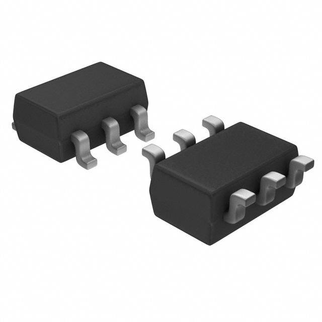
ICGOO电子元器件商城为您提供TC670ECHTR由Microchip设计生产,在icgoo商城现货销售,并且可以通过原厂、代理商等渠道进行代购。 TC670ECHTR价格参考¥6.20-¥6.20。MicrochipTC670ECHTR封装/规格:PMIC - 热管理, Fan Control, Temp Monitor -40°C ~ 85°C Internal Sensor Open Drain Output SOT-23-6。您可以下载TC670ECHTR参考资料、Datasheet数据手册功能说明书,资料中有TC670ECHTR 详细功能的应用电路图电压和使用方法及教程。
| 参数 | 数值 |
| 产品目录 | 集成电路 (IC)半导体 |
| 描述 | IC FAN FAILURE DETECTOR SOT23A-6马达/运动/点火控制器和驱动器 Predictive Fan Failure Det |
| 产品分类 | |
| 品牌 | Microchip Technology |
| 产品手册 | |
| 产品图片 |
|
| rohs | 符合RoHS无铅 / 符合限制有害物质指令(RoHS)规范要求 |
| 产品系列 | 电源管理 IC,马达/运动/点火控制器和驱动器,Microchip Technology TC670ECHTR- |
| 数据手册 | http://www.microchip.com/mymicrochip/filehandler.aspx?ddocname=en011659 |
| 产品型号 | TC670ECHTR |
| 产品 | Fan / Motor Controllers / Drivers |
| 产品目录页面 | |
| 产品种类 | 马达/运动/点火控制器和驱动器 |
| 传感器类型 | 内部 |
| 供应商器件封装 | SOT-23-6 |
| 其它名称 | TC670ECHTRDKR |
| 功能 | 风扇控制,温度监控器 |
| 包装 | Digi-Reel® |
| 商标 | Microchip Technology |
| 安装类型 | 表面贴装 |
| 安装风格 | SMD/SMT |
| 封装 | Reel |
| 封装/外壳 | SOT-23-6 |
| 封装/箱体 | SOT-23A-6 |
| 工作温度 | -40°C ~ 85°C |
| 工作电源电压 | 3 V to 5.5 V |
| 工厂包装数量 | 3000 |
| 感应温度 | -40°C ~ 85°C |
| 拓扑 | |
| 标准包装 | 1 |
| 电压-电源 | 3 V ~ 5.5 V |
| 电源电流 | 150 uA |
| 类型 | Predictive Fan Fault Detector |
| 精度 | - |
| 输出报警 | 是 |
| 输出电压 | 0.3 V |
| 输出端数量 | 1 |
| 输出类型 | 开路漏极 |
| 输出风扇 | 是 |


- 商务部:美国ITC正式对集成电路等产品启动337调查
- 曝三星4nm工艺存在良率问题 高通将骁龙8 Gen1或转产台积电
- 太阳诱电将投资9.5亿元在常州建新厂生产MLCC 预计2023年完工
- 英特尔发布欧洲新工厂建设计划 深化IDM 2.0 战略
- 台积电先进制程称霸业界 有大客户加持明年业绩稳了
- 达到5530亿美元!SIA预计今年全球半导体销售额将创下新高
- 英特尔拟将自动驾驶子公司Mobileye上市 估值或超500亿美元
- 三星加码芯片和SET,合并消费电子和移动部门,撤换高东真等 CEO
- 三星电子宣布重大人事变动 还合并消费电子和移动部门
- 海关总署:前11个月进口集成电路产品价值2.52万亿元 增长14.8%


PDF Datasheet 数据手册内容提取
M TC670 Tiny Predictive Fan Failure Detector Features General Description • Fan Wear-Out Detection for 2-Wire The TC670 is an integrated fan speed sensor that Linear-Controlled Fans predicts and/or detects fan failure, preventing thermal • Replacement System for 3-Wire Fans damage to systems with cooling fans. When the fan speed falls below a user-specified level, the TC670 • Fan Alert Signal when Fan Speed is below asserts an ALERT signal. With this design, a critical Programmed Threshold minimum fan speed is determined by the user. The fan • CLEAR Capability for Eliminating False Alarm alert level is then set with a resistor divider on the • Low Operating Current, 90µA (typ.) THRESHOLD pin (Pin 1) of the TC670. When the • VDD Range 3.0V to 5.5V minimum fan speed is reached, the ALERT pin (Pin 5) • Available in a 6-Pin SOT-23 Package changes from a digital high to low. This failure detection works with all linear-controlled 2-wire fans. The TC670 Applications eliminates the need for 3-wire fan solutions. • Protection for Linear-Controlled Fans A CLEAR option can be used to reset the ALERT sig- nal, allowing the flexibility of connecting the ALERT • Power Supplies output of the TC670 with other ALERT/FAULT inter- • Industrial Equipment rupts in the system. This feature can be implemented • PCs and Notebooks so that false fan fault conditions do not initiate system • Data Storage shutdown. • Data Communications Equipment The TC670 is specified to operate over the full • Instrumentation industrial temperature range of -40°C to +85°C. The TC670 is offered in a 6-pin SOT-23 pin package and Package Type consumes 90µA (typ.) during operation. The space- saving package and low power consumption make this SOT-23A-6 device an ideal choice for systems requiring fan speed monitoring. THRESHOLD 1 6 SENSE Typical Application Circuit 70 +5V GND 2 6 5 ALERT C T CLEAR 3 4 V DD ALERT 4 LED V DD 0.1µF R 4 CLEAR +12V 3 ALERT 5 From R 3 Microcontroller DDCC 1 FFAANN THRESHOLD C 6 SENSE SENSE R 2 R GND SENSE 2 2003 Microchip Technology Inc. DS21688C-page 1
TC670 1.0 ELECTRICAL TABLE 1-1: PIN FUNCTION TABLE CHARACTERISTICS Symbol Description THRESHOLD Analog Input Absolute Maximum Ratings† GND Ground Terminal V ...................................................................................6.0V DD CLEAR Digital Input All Inputs and Outputs. ............(GND − 0.3V) to (V + 0.3V) DD VDD Bias Supply Input Output Short-Circuit Current .................................continuous ALERT Digital (Open-Drain) Output Current at Input Pin ...................................................+/-2mA Current at Output Pin ..............................................+/-25mA SENSE Analog Input Junction Temperature, T .............................................150°C J ESD protection on all pins..................................................≥ 4kV Operating Temperature Range........................-40°C to +85°C Storage Temperature Range.........................-55°C to +150°C † Notice: Stresses above those listed under "Maximum Ratings" may cause permanent damage to the device. This is a stress rating only and functional operation of the device at those or any other conditions above those indicated in the operation listings of this specification is not implied. Exposure to maximum rating conditions for extended periods may affect device reliability. DC CHARACTERISTICS Electrical Specifications: Unless otherwise specified, all limits are specified at +25°C, V = 3.0V to 5.5V, DD CLEAR = Low. Boldface type specifications apply for temperature range of -40°C to +85°C. Parameters Sym Min Typ Max Units Conditions Power Supply Supply Voltage V 3.0 — 5.5 V DD Supply Current I — 90 150 µA DD CLEAR Input Logic Input High Level V 0.8V — — V IH DD Logic Input Low Level V — — 0.2V V IL DD SENSE Input Input Level Threshold Voltage V — 124 — mV TH(SENSE) Input Resistance R — 50 — kΩ SENSE THRESHOLD Input Input Voltage Minimum — 0.0 — V Input Voltage Maximum — 2.4 — V Input Resistance — 100 — MΩ Programmed Fan Speed Alert Accuracy ALERT -10 — +10 % V = 3.0V ACC DD (Note1) ALERT Output Output Low Voltage V — — 0.3 V I = 2.5mA LOW SINK Output Delay Time t — 176 — ms DELAY Temperature Ranges Specified Temperature Range T -40 — +85 °C A Operating Temperature Range T -40 — +125 °C A Thermal Package Resistances Thermal Resistance, 6L-SOT-23 θ — 230 — °C/W JA Note 1: The TC670 will operate properly over the entire power supply range of 3.0V to 5.5V. As V varies from DD 3.0V, accuracy will degrade based on the percentage of V , as shown in Section2.0, “Typical DD Performance Curves”. DS21688C-page 2 2003 Microchip Technology Inc.
TC670 2.0 TYPICAL PERFORMANCE CURVES Note: The graphs and tables provided following this note are a statistical summary based on a limited number of samples and are provided for informational purposes only. The performance characteristics listed herein are not tested or guaranteed. In some graphs or tables, the data presented may be outside the specified operating range (e.g., outside specified power supply range) and therefore outside the warranted range. Note: Unless otherwise indicated, all limits are specified at +25°C, V = 3.0V to 5.5V, CLEAR = Low. DD 115 160 110 +90°C 140 A) 105 mV) 120 VDD = 3.0V urrent (µ 10905 +25°C LOW ( 18000 pply C 90 OUT 60 Su 85 -45°C T V 40 VDD = 5.5V 80 ER 20 L 75 A 0 70 0.5 1 1.5 2 2.5 3 3.5 4 4.5 2.7 3.0 3.3 3.6 3.9 4.2 4.5 4.8 5.1 5.4 5.7 6.0 ALERT ISINK (mA) Supply Voltage (V) FIGURE 2-1: Supply Current vs. Supply FIGURE 2-4: ALERT V vs. ALERT LOW Voltage. I . SINK 15000 14000 13000 13000 12000 12000 11000 TA = -40˚C 1101000000 VDD = 3.0V 10000 TA = +25˚C Fan Speed (RPM) 23456789000000000000000000000000 VDD = 2.7V VDD = 3.3V )AN SPEED (RPM 456789000000000000000000 TA = V+D9D0˚ =C 3.0V 1000 F 3000 0 -10.0-8.0 -6.0 -4.0 -2.0 0.0 2.0 4.0 6.0 8.0 10.0 0.00 0.25 0.50 0.75 1.00 1.25 1.50 1.75 2.00 2.25 2.50 THRESHOLD Voltage (V) ALERTACC (%) FIGURE 2-2: Fan Speed vs. Threshold FIGURE 2-5: Fan Speed vs. ALERT . Voltage. ACC 15000 1134000000 VDD = 3.6V 177 12000 s) 176 11000 m 10000 e ( 175 M) 9000 m Fan Speed (RP 345678000000000000000000 VDD = V5D.0DV = 5.5V utput Delay Ti 111177771234 12000000 RT O 170 0 ALE 169 0.00 0.25 0.50 0.75 1.00 1.25 1.50 1.75 2.00 2.25 2.50 168 THRESHOLD Voltage (V) 2.5 3.0 3.5 4.0 4.5 5.0 FIGURE 2-3: Fan Speed vs. Threshold Power Supply Voltage (VDD) Voltage. FIGURE 2-6: ALERT Output Delay vs. Power Supply Voltage. 2003 Microchip Technology Inc. DS21688C-page 3
TC670 Note: Unless otherwise indicated, all limits are specified at +25°C, V = 3.0V to 5.5V, CLEAR = Low. DD FIGURE 2-7: CLEAR pin high to ALERT pin high Timing Diagram. DS21688C-page 4 2003 Microchip Technology Inc.
TC670 3.0 PIN DESCRIPTIONS 3.3 Digital Input (CLEAR) The descriptions of the pins are listed in Table3-1. The CLEAR input is used to reset or blank the ALERT output. When the CLEAR input is driven high, the TABLE 3-1: PIN FUNCTION TABLE ALERT output will be high-impedance (the ALERT output requires a pull-up resistor). Pin Symbol Description No. 3.4 Bias Supply Input (V ) DD 1 THRESHOLD Analog Input Bias Supply Input, 3.0V to 5.5V. The bias supply input 2 GND Ground Terminal should be bypassed to ground with a 0.1µF ceramic 3 CLEAR Digital Input capacitor. 4 VDD Bias Supply Input 3.5 Digital (Open-Drain) Output 5 ALERT Digital (Open-Drain) Output (ALERT) 6 SENSE Analog Input The ALERT output is an open-drain output that 3.1 Analog Input (THRESHOLD) requires an external pull-up resistor. The ALERT output is pulled low when the sensed fan speed (detected by The voltage set at the THRESHOLD input represents the pulses occurring at the SENSE input) falls below the fan speed at which the TC670 will signal a fan the speed that is represented by the voltage at the speed warning by pulling the ALERT output low. The THRESHOLD pin. The ALERT output is latched in this threshold voltage to fan speed correlation can be seen state until power is cycled or the CLEAR input is in Figures2-2 and2-3. toggled. 3.2 Ground (GND) 3.6 Analog Input (SENSE) The GND pin (Pin 2) of the TC670 should be connected Voltage pulses, which are generated by the fan current directly to the analog ground plane of the circuit board. flowing through a sense resistor, are detected at the Care should be taken to keep this pin away from SENSE pin and used to calculate the fan speed. switching signals, such as the fan excitation signals in order to avoid false signals on the SENSE pin. 2003 Microchip Technology Inc. DS21688C-page 5
TC670 4.0 DETAILED DESCRIPTION +5V The TC670 is an integrated fan speed sensor that predicts/detects fan failure, consequently preventing thermal damage to systems with cooling fans. When the fan speed falls below a user-programmed threshold ALERT level, the TC670 asserts an ALERT signal. This 4 LED V threshold is set with an external resistor divider DD network. 0.1µF R 4 CLEAR +12V 3 ALERT 5 VDD R3 CLEAR DDCC 1 FFAANN THRESHOLD C THRESHOLD Logic ALERT SENSE6 SENSE R 2 R GND SENSE 50kΩ 2 Frequency-to- SENSE Voltage GND Note: This typical application circuit uses a LED to 124mV Bandgap Oscillator indicate that a fan failure has occurred. FIGURE 4-2: Typical Application Circuit. FIGURE 4-1: TC670 Block Diagram. 4.1 SENSE Input As shown in Figure4-1, the TC670 senses the fan As shown in Figure4-2, the SENSE input (Pin 6) is pulses and internally converts those pulses from a connected to the sense resistor (R ) through a SENSE frequency into an analog voltage. This voltage is then capacitor (C ). The low value current sensing SENSE compared with the DC voltage at the THRESHOLD pin. resistor (R ) is connected between the ground SENSE If the converted frequency-to-voltage value from the return leg of the fan and the fan bias ground. During fan's pulses falls below the threshold voltage, the normal fan operation, commutation occurs as each ALERT output is pulled low. pole of the fan is energized. This causes the fan current to be an AC waveform with fast falling edges. In a 3.0V system, the external fan alert level on the THRESHOLD pin can be designed from 0.0V (stalled These short, rapid changes in fan current cause a fan) to 2.4V (for 13,000RPM) to cover most of the com- corresponding dV/dt voltage across the sense resistor, mon fan speeds. This failure detection system works as well as a corresponding dI/dt current through the with linear-controlled 2-wire fans and eliminates the sense capacitor. The current through C is termi- SENSE need for 3-wire fans. The TC670 can also work with nated with the internal 50kΩ input resistance at the 3-wire fans either by using the SENSE circuit or by SENSE pin of the TC670. When positive-going fan directly sensing the RPM output from the 3rd wire. pulses at the SENSE input are greater than 124mV (typ.), the TC670 latches-in those voltage spikes. This A CLEAR pin is provided to allow the user to reset the 124mV (typ.) SENSE input built-in threshold reduces ALERT pin status back to a high state. This clear option false triggering errors caused by extraneous noise also allows the flexibility of connecting the ALERT out- pulses associated with a running fan. The presence put of the TC670 with other alert/fault interrupts in the and frequency of these pulses is a direct indication of system without having a risk of a system shutdown due fan operation and fan speed. to false fan fault condition. DS21688C-page 6 2003 Microchip Technology Inc.
TC670 The design of the proper input SENSE circuitry is a 4.2.1 THRESHOLD CALIBRATION USING matter of scaling RSENSE to provide the necessary FAN’S FULL SCALE SPEED amount of gain and proper selection of the sensing capacitor. The following table (Table4-1) lists some The fan should first be run at full speed. At full speed, recommended values for R according to the the threshold voltage level should be adjusted until the SENSE nominal operating current of the fan. Please note that ALERT output is asserted. With this full-scale value of the threshold voltage, the value can be scaled down to the current draw specified by the fan manufacturer may the fan fault speed as a percentage of the full speed. be a worst-case rating and not the fan’s nominal oper- For example, if the fan full speed threshold voltage is ating current. If the fan current falls between two of the values listed, it is recommended that the higher value 1.5V, then the fan fault threshold voltage at 30% of full resistor is used. speed would be 30% x 1.5V = 0.45V. 4.2.2 THRESHOLD CALIBRATION USING TABLE 4-1: RECOMMENDED VALUES FAN’S MINIMUM ALLOWABLE FOR R PER FIGURE4-2 SENSE SPEED ESTIMATE Nominal Fan Current (mA) RSENSE (Ω) For a more exact fan fault trip point, the user can run the fan at its minimum allowed speed. At this speed, 100 4.7 the threshold voltage can be adjusted until the ALERT 200 2.4 output is asserted. 300 1.8 4.3 CLEAR Input 400 1.3 The CLEAR input allows the user to reset the ALERT 500 1.0 pin to a high status. This is an active-high input. 600 0.8 Consequently, as long as CLEAR is high, ALERT will A 0.1µF ceramic capacitor is recommended for always be high as well. To allow ALERT to operate cor- C . Smaller capacitor values will require larger rectly, CLEAR must be held low. This feature can be SENSE sense resistors, whereas larger capacitors are more implemented so that false fan fault conditions do not expensive and occupy more board space. initiate system shutdown. 4.2 THRESHOLD Input 4.4 ALERT Output The voltage at the THRESHOLD input sets the The ALERT output is an open-drain output capable of equivalent minimum allowable fan speed for the appli- sinking 2.5mA (typ). The ALERT output is asserted cation. As shown in Section2.0, “Typical Performance whenever the detected fan speed equals or falls below Curves”, the relationship between the threshold volt- the equivalent voltage set at the threshold pin. The age and minimum fan speed is also power supply and ALERT output is only deactivated once the CLEAR pin temperature dependant. is brought to a high state. Although the absolute maximum sink current of this pin is 25mA, it is All the values for the threshold voltage that are shown recommended that the current sinking into the ALERT in these graphs represent typical numbers and might output does not exceed 20mA. not be optimized for all fans in all applications. To ensure accurate fan speed monitoring of a specific fan 4.5 Power Supply Input (V ) in a specific application, the user must perform a one- DD time correlation check with the prototype. To assure proper operation of the TC670 in a noisy There are two techniques that can be used to calibrate environment where the fans are running, the VDD pin the system. One approach is to find the fan’s full-scale (Pin 4) must be decoupled with a 0.1µF capacitor, as capability and mathematically estimate the minimum shown in Figure4-1. This capacitor should be located acceptable speed of the fan. A second technique is to as close to the TC670 VDD pin as possible, as well as identify the fan’s minimum speed and calibrate the being promptly terminated to the ground plane. A threshold voltage accordingly. ceramic capacitor is recommended. 4.6 Ground Terminal (GND) The GND pin (Pin 2) of the TC670 should be connected directly to the analog ground plane of the circuit board. Care should be taken to keep this pin away from switching signals, such as the fan excitation signals in order to avoid false signals on the SENSE pin. 2003 Microchip Technology Inc. DS21688C-page 7
TC670 5.0 PACKAGE INFORMATION 5.1 Package Marking Information 6-Pin SOT-23A (EIAJ SC-74) Device 6 5 4 (cid:99)(cid:100)(cid:101)(cid:102) 1 2 3 1 & 2 = part number code Part Number Code TC670ECH DA 3 = year and quarter code 4 = lot ID number 5.2 Taping Form Component Taping Orientation for 6-Pin SOT-23A (EIAJ SC-74) Devices User Direction of Feed Device Marking W P PIN 1 Carrier Tape, Number of Components Per Reel and Reel Size: Package Carrier Width (W) Pitch (P) Part Per Full Reel Reel Size 6-Pin SOT-23A 8 mm 4 mm 3000 7 in. DS21688C-page 8 2003 Microchip Technology Inc.
TC670 5.3 Package Dimensions (6-Pin SOT-23) E E1 B p1 D n 1 α c A A2 φ A1 L β Units INCHES* MILLIMETERS Dimension Limits MIN NOM MAX MIN NOM MAX Number of Pins n 6 6 Pitch p .038 0.95 Outside lead pitch (basic) p1 .075 1.90 Overall Height A .035 .046 .057 0.90 1.18 1.45 Molded Package Thickness A2 .035 .043 .051 0.90 1.10 1.30 Standoff A1 .000 .003 .006 0.00 0.08 0.15 Overall Width E .102 .110 .118 2.60 2.80 3.00 Molded Package Width E1 .059 .064 .069 1.50 1.63 1.75 Overall Length D .110 .116 .122 2.80 2.95 3.10 Foot Length L .014 .018 .022 0.35 0.45 0.55 Foot Angle φ 0 5 10 0 5 10 Lead Thickness c .004 .006 .008 0.09 0.15 0.20 Lead Width B .014 .017 .020 0.35 0.43 0.50 Mold Draft Angle Top α 0 5 10 0 5 10 Mold Draft Angle Bottom β 0 5 10 0 5 10 *Controlling Parameter Notes: Dimensions D and E1 do not include mold flash or protrusions. Mold flash or protrusions shall not exceed .005" (0.127mm) per side. JEITA (formerly EIAJ) equivalent: SC-74A Drawing No. C04-120 2003 Microchip Technology Inc. DS21688C-page 9
TC670 NOTES: DS21688C-page 10 2003 Microchip Technology Inc.
TC670 PRODUCT IDENTIFICATION SYSTEM To order or obtain information, e.g., on pricing or delivery, refer to the factory or the listed sales office. PART NO. X XXXX Examples: Device Temperature Package a) TC670ECHTR: Predictive Fan Failure Range Detector, SOT-23 package. Device: TC670: Predictive Fan Failure Detector Temperature Range: E = -40°C to +85°C Package: CHTR: = SOT-23, Small Outline Transistor, 6-lead (Tape and Reel only) Sales and Support Data Sheets Products supported by a preliminary Data Sheet may have an errata sheet describing minor operational differences and recom- mended workarounds. To determine if an errata sheet exists for a particular device, please contact one of the following: 1. Your local Microchip sales office 2. The Microchip Corporate Literature Center U.S. FAX: (480) 792-7277 3. The Microchip Worldwide Site (www.microchip.com) Please specify which device, revision of silicon and Data Sheet (include Literature #) you are using. Customer Notification System Register on our web site (www.microchip.com/cn) to receive the most current information on our products. 2003 Microchip Technology Inc. DS21688C-page11
TC670 NOTES: DS21688C-page 12 2003 Microchip Technology Inc.
Note the following details of the code protection feature on Microchip devices: • Microchip products meet the specification contained in their particular Microchip Data Sheet. • Microchip believes that its family of products is one of the most secure families of its kind on the market today, when used in the intended manner and under normal conditions. • There are dishonest and possibly illegal methods used to breach the code protection feature. All of these methods, to our knowledge, require using the Microchip products in a manner outside the operating specifications contained in Microchip's Data Sheets. Most likely, the person doing so is engaged in theft of intellectual property. • Microchip is willing to work with the customer who is concerned about the integrity of their code. • Neither Microchip nor any other semiconductor manufacturer can guarantee the security of their code. Code protection does not mean that we are guaranteeing the product as “unbreakable.” Code protection is constantly evolving. We at Microchip are committed to continuously improving the code protection features of our products. Attempts to break microchip’s code protection feature may be a violation of the Digital Millennium Copyright Act. If such acts allow unauthorized access to your software or other copyrighted work, you may have a right to sue for relief under that Act. Information contained in this publication regarding device Trademarks applications and the like is intended through suggestion only and may be superseded by updates. It is your responsibility to The Microchip name and logo, the Microchip logo, KEELOQ, ensure that your application meets with your specifications. No MPLAB, PIC, PICmicro, PICSTART, PRO MATE and representation or warranty is given and no liability is assumed PowerSmart are registered trademarks of Microchip Technology by Microchip Technology Incorporated with respect to the Incorporated in the U.S.A. and other countries. accuracy or use of such information, or infringement of patents FilterLab, microID, MXDEV, MXLAB, PICMASTER, SEEVAL or other intellectual property rights arising from such use or and The Embedded Control Solutions Company are registered otherwise. Use of Microchip’s products as critical components in trademarks of Microchip Technology Incorporated in the U.S.A. life support systems is not authorized except with express written approval by Microchip. No licenses are conveyed, Accuron, Application Maestro, dsPIC, dsPICDEM, implicitly or otherwise, under any intellectual property rights. dsPICDEM.net, ECONOMONITOR, FanSense, FlexROM, fuzzyLAB, In-Circuit Serial Programming, ICSP, ICEPIC, microPort, Migratable Memory, MPASM, MPLIB, MPLINK, MPSIM, PICC, PICkit, PICDEM, PICDEM.net, PowerCal, PowerInfo, PowerMate, PowerTool, rfLAB, rfPIC, Select Mode, SmartSensor, SmartShunt, SmartTel and Total Endurance are trademarks of Microchip Technology Incorporated in the U.S.A. and other countries. Serialized Quick Turn Programming (SQTP) is a service mark of Microchip Technology Incorporated in the U.S.A. All other trademarks mentioned herein are property of their respective companies. © 2003, Microchip Technology Incorporated, Printed in the U.S.A., All Rights Reserved. Printed on recycled paper. Microchip received QS-9000 quality system certification for its worldwide headquarters, design and wafer fabrication facilities in Chandler and Tempe, Arizona in July 1999 and Mountain View, California in March 2002. The Company’s quality system processes and procedures are QS-9000 compliant for its PICmicro® 8-bit MCUs, KEELOQ® code hopping devices, Serial EEPROMs, microperipherals, non-volatile memory and analog products. In addition, Microchip’s quality system for the design and manufacture of development systems is ISO 9001 certified. 2003 Microchip Technology Inc. DS21688C - page 13
M WORLDWIDE SALES AND SERVICE AMERICAS ASIA/PACIFIC Japan Corporate Office Australia Microchip Technology Japan K.K. Benex S-1 6F 2355 West Chandler Blvd. Microchip Technology Australia Pty Ltd 3-18-20, Shinyokohama Chandler, AZ 85224-6199 Marketing Support Division Kohoku-Ku, Yokohama-shi Tel: 480-792-7200 Fax: 480-792-7277 Suite 22, 41 Rawson Street Kanagawa, 222-0033, Japan Technical Support: 480-792-7627 Epping 2121, NSW Tel: 81-45-471- 6166 Fax: 81-45-471-6122 Web Address: http://www.microchip.com Australia Korea Rocky Mountain Tel: 61-2-9868-6733 Fax: 61-2-9868-6755 China - Beijing Microchip Technology Korea 2355 West Chandler Blvd. 168-1, Youngbo Bldg. 3 Floor Chandler, AZ 85224-6199 Microchip Technology Consulting (Shanghai) Samsung-Dong, Kangnam-Ku Tel: 480-792-7966 Fax: 480-792-4338 Co., Ltd., Beijing Liaison Office Seoul, Korea 135-882 Unit 915 Atlanta Tel: 82-2-554-7200 Fax: 82-2-558-5934 Bei Hai Wan Tai Bldg. 3780 Mansell Road, Suite 130 No. 6 Chaoyangmen Beidajie Singapore Alpharetta, GA 30022 Beijing, 100027, No. China Microchip Technology Singapore Pte Ltd. Tel: 770-640-0034 Fax: 770-640-0307 Tel: 86-10-85282100 Fax: 86-10-85282104 200 Middle Road Boston China - Chengdu #07-02 Prime Centre Singapore, 188980 2 Lan Drive, Suite 120 Microchip Technology Consulting (Shanghai) Tel: 65-6334-8870 Fax: 65-6334-8850 Westford, MA 01886 Co., Ltd., Chengdu Liaison Office Tel: 978-692-3848 Fax: 978-692-3821 Rm. 2401-2402, 24th Floor, Taiwan Microchip Technology (Barbados) Inc., Chicago Ming Xing Financial Tower No. 88 TIDU Street Taiwan Branch 333 Pierce Road, Suite 180 Chengdu 610016, China 11F-3, No. 207 Itasca, IL 60143 Tung Hua North Road Tel: 630-285-0071 Fax: 630-285-0075 Tel: 86-28-86766200 Fax: 86-28-86766599 Taipei, 105, Taiwan China - Fuzhou Dallas Tel: 886-2-2717-7175 Fax: 886-2-2545-0139 Microchip Technology Consulting (Shanghai) 4570 Westgrove Drive, Suite 160 Co., Ltd., Fuzhou Liaison Office EUROPE Addison, TX 75001 Tel: 972-818-7423 Fax: 972-818-2924 Unit 28F, World Trade Plaza Austria No. 71 Wusi Road Detroit Fuzhou 350001, China Microchip Technology Austria GmbH Durisolstrasse 2 Tri-Atria Office Building Tel: 86-591-7503506 Fax: 86-591-7503521 A-4600 Wels 32255 Northwestern Highway, Suite 190 China - Hong Kong SAR Farmington Hills, MI 48334 Austria Microchip Technology Hongkong Ltd. Tel: 43-7242-2244-399 Tel: 248-538-2250 Fax: 248-538-2260 Unit 901-6, Tower 2, Metroplaza Fax: 43-7242-2244-393 Kokomo 223 Hing Fong Road Denmark 2767 S. Albright Road Kwai Fong, N.T., Hong Kong Microchip Technology Nordic ApS Kokomo, Indiana 46902 Tel: 852-2401-1200 Fax: 852-2401-3431 Regus Business Centre Tel: 765-864-8360 Fax: 765-864-8387 China - Shanghai Lautrup hoj 1-3 Los Angeles Microchip Technology Consulting (Shanghai) Ballerup DK-2750 Denmark 18201 Von Karman, Suite 1090 Co., Ltd. Tel: 45 4420 9895 Fax: 45 4420 9910 Irvine, CA 92612 Room 701, Bldg. B France Far East International Plaza Tel: 949-263-1888 Fax: 949-263-1338 Microchip Technology SARL No. 317 Xian Xia Road Parc d’Activite du Moulin de Massy San Jose Shanghai, 200051 43 Rue du Saule Trapu Microchip Technology Inc. Tel: 86-21-6275-5700 Fax: 86-21-6275-5060 Batiment A - ler Etage 2107 North First Street, Suite 590 China - Shenzhen 91300 Massy, France San Jose, CA 95131 Microchip Technology Consulting (Shanghai) Tel: 33-1-69-53-63-20 Fax: 33-1-69-30-90-79 Tel: 408-436-7950 Fax: 408-436-7955 Co., Ltd., Shenzhen Liaison Office Germany Toronto Rm. 1812, 18/F, Building A, United Plaza Microchip Technology GmbH 6285 Northam Drive, Suite 108 No. 5022 Binhe Road, Futian District Steinheilstrasse 10 Mississauga, Ontario L4V 1X5, Canada Shenzhen 518033, China D-85737 Ismaning, Germany Tel: 905-673-0699 Fax: 905-673-6509 Tel: 86-755-82901380 Fax: 86-755-82966626 Tel: 49-089-627-144-100 China - Qingdao Fax: 49-089-627-144-44 Rm. B505A, Fullhope Plaza, Italy No. 12 Hong Kong Central Rd. Microchip Technology SRL Qingdao 266071, China Via Quasimodo, 12 Tel: 86-532-5027355 Fax: 86-532-5027205 20025 Legnano (MI) India Milan, Italy Microchip Technology Inc. Tel: 39-0331-742611 Fax: 39-0331-466781 India Liaison Office United Kingdom Marketing Support Division Microchip Ltd. Divyasree Chambers 505 Eskdale Road 1 Floor, Wing A (A3/A4) Winnersh Triangle No. 11, O’Shaugnessey Road Wokingham Bangalore, 560 025, India Berkshire, England RG41 5TU Tel: 91-80-2290061 Fax: 91-80-2290062 Tel: 44 118 921 5869 Fax: 44-118 921-5820 02/12/03 DS21688B-page 14 2003 Microchip Technology Inc.
Mouser Electronics Authorized Distributor Click to View Pricing, Inventory, Delivery & Lifecycle Information: M icrochip: TC670ECHTR