ICGOO在线商城 > 开发板,套件,编程器 > 评估板 - 音频放大器 > TAS5713PHPEVM

 Datasheet下载
- 型号: TAS5713PHPEVM
- 制造商: Texas Instruments
- 库位|库存: xxxx|xxxx
- 要求:
| 数量阶梯 | 香港交货 | 国内含税 |
| +xxxx | $xxxx | ¥xxxx |
查看当月历史价格
查看今年历史价格
TAS5713PHPEVM产品简介:
ICGOO电子元器件商城为您提供TAS5713PHPEVM由Texas Instruments设计生产,在icgoo商城现货销售,并且可以通过原厂、代理商等渠道进行代购。 TAS5713PHPEVM价格参考¥1001.20-¥1001.20。Texas InstrumentsTAS5713PHPEVM封装/规格:评估板 - 音频放大器, TAS5713PHP - 2-Channel (Stereo) Output Class D Audio Amplifier Evaluation Board。您可以下载TAS5713PHPEVM参考资料、Datasheet数据手册功能说明书,资料中有TAS5713PHPEVM 详细功能的应用电路图电压和使用方法及教程。
| 参数 | 数值 |
| 产品目录 | 编程器,开发系统嵌入式解决方案 |
| 描述 | EVAL MODULE FOR TAS5713PHP音频 IC 开发工具 TAS5713PHP Eval Mod |
| 产品分类 | |
| 品牌 | Texas Instruments |
| 产品手册 | |
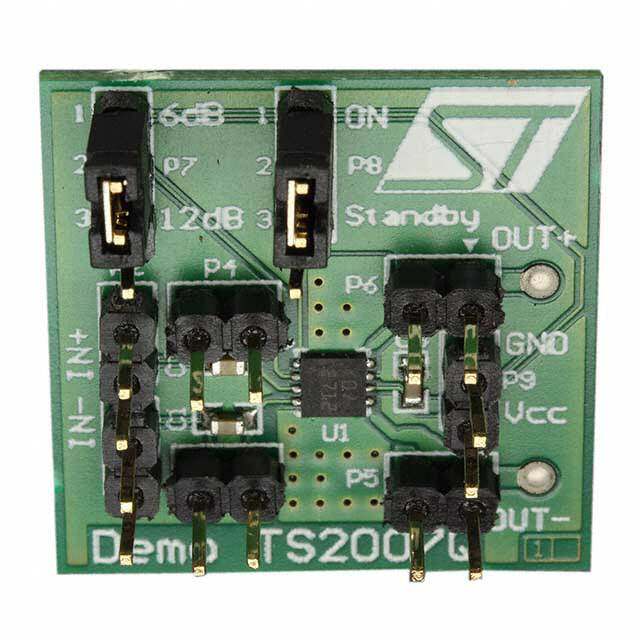
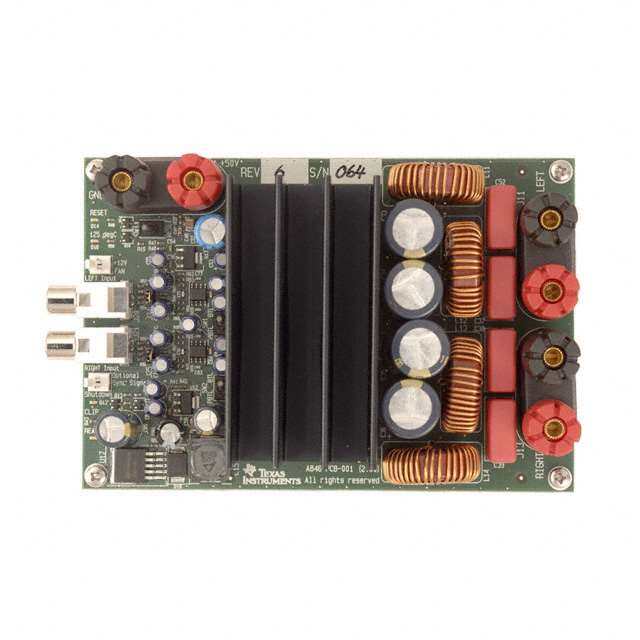
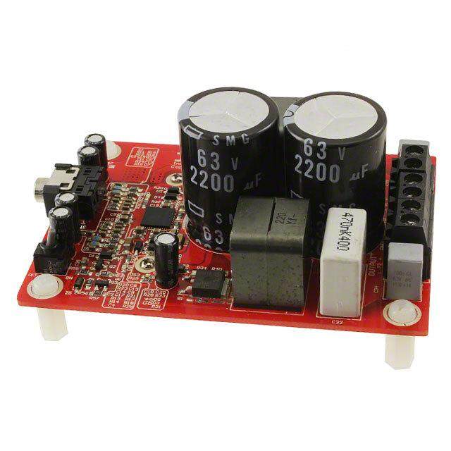
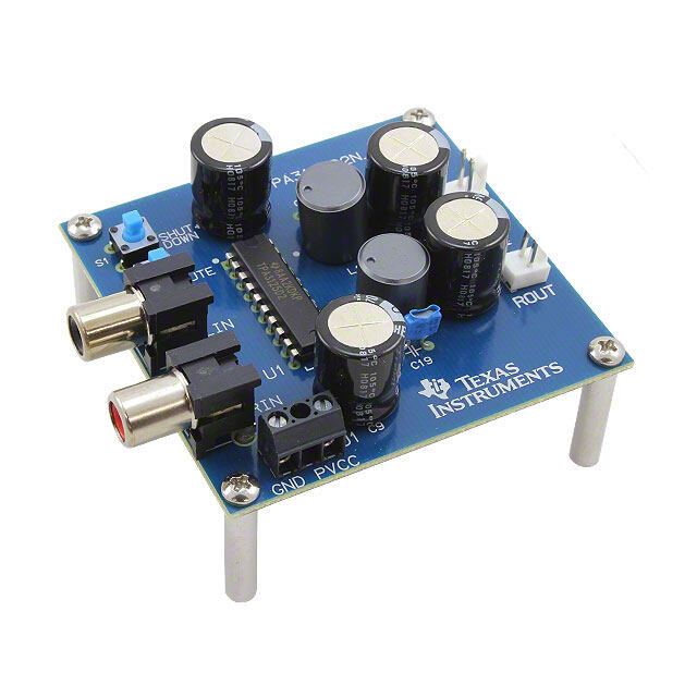
| 产品图片 |
|
| rohs | 否无铅 / 符合限制有害物质指令(RoHS)规范要求 |
| 产品系列 | 模拟与数字IC开发工具,音频 IC 开发工具,Texas Instruments TAS5713PHPEVM- |
| 数据手册 | 点击此处下载产品Datasheethttp://www.ti.com/lit/pdf/slou281 |
| 产品型号 | TAS5713PHPEVM |
| 不同负载时的最大输出功率x通道数 | 25W x 2 @ 8 欧姆 |
| 产品 | Evaluation Modules |
| 产品种类 | 音频 IC 开发工具 |
| 使用的IC/零件 | TAS5713PHP |
| 其它名称 | 296-31009 |
| 制造商产品页 | http://www.ti.com/general/docs/suppproductinfo.tsp?distId=10&orderablePartNumber=TAS5713PHPEVM |
| 商标 | Texas Instruments |
| 工作温度 | - |
| 工作电源电压 | 5 V |
| 工作电源电流 | 1 A |
| 工具用于评估 | TAS5713 |
| 工厂包装数量 | 1 |
| 所含物品 | 板 |
| 接口类型 | I2S, USB |
| 放大器类型 | D 类 |
| 板类型 | 完全填充 |
| 标准包装 | 1 |
| 电压-电源 | 8 V ~ 26 V |
| 类型 | Audio Amplifiers |
| 输出类型 | 2 通道(立体声) |


- 商务部:美国ITC正式对集成电路等产品启动337调查
- 曝三星4nm工艺存在良率问题 高通将骁龙8 Gen1或转产台积电
- 太阳诱电将投资9.5亿元在常州建新厂生产MLCC 预计2023年完工
- 英特尔发布欧洲新工厂建设计划 深化IDM 2.0 战略
- 台积电先进制程称霸业界 有大客户加持明年业绩稳了
- 达到5530亿美元!SIA预计今年全球半导体销售额将创下新高
- 英特尔拟将自动驾驶子公司Mobileye上市 估值或超500亿美元
- 三星加码芯片和SET,合并消费电子和移动部门,撤换高东真等 CEO
- 三星电子宣布重大人事变动 还合并消费电子和移动部门
- 海关总署:前11个月进口集成电路产品价值2.52万亿元 增长14.8%


PDF Datasheet 数据手册内容提取
User's Guide SLOU281–January2010 25W Digital Input Amplifier With EQ and 2-Band DRC This manual describes the operation of the TAS5713EVM to evaluate the performance of the TAS5713 integrateddigitalaudiopoweramplifier.Themaincontentsofthisdocumentare: • HowtoproperlyconnectaTAS5713EvaluationModule(EVM)andthedetailsoftheEVM • HowtoinstallandusetheGUItoprogramtheTAS5713EVM • HowtousetheaudioprocessingfeaturessuchasEQandDynamicRangeControl(DRC) • Quick-StartGuideforthecommonmodesinwhichTAS5713EVMcanbeused Contents 1 Overview ..................................................................................................................... 3 1.1 TAS5713EVMandMC57xxPSIAFeatures ..................................................................... 4 2 Installation.................................................................................................................... 4 2.1 EVMInstallation .................................................................................................... 4 2.2 SoftwareInstallation ............................................................................................... 7 3 UsingtheEVMSoftware ................................................................................................... 9 3.1 ConnecttheGUItotheEVM ..................................................................................... 9 3.2 I2CMemoryTool ................................................................................................... 9 3.3 VolumeFunction .................................................................................................. 10 3.4 BiquadGUI ........................................................................................................ 10 3.5 DRCGUI........................................................................................................... 11 4 JumpersandControlUtilitiesonMC57xxPSIAboard ................................................................ 13 4.1 RCA/OPTICALJumpers ......................................................................................... 13 4.2 Switches ........................................................................................................... 13 4.3 LEDIndicators .................................................................................................... 13 5 BoardLayouts,BillofMaterials,andSchematic ...................................................................... 14 5.1 TAS5713EVMandMC57xxPSIABoardLayouts ............................................................ 14 5.2 BillofMaterials.................................................................................................... 16 5.3 Schematics ........................................................................................................ 17 ListofFigures 1 TAS5713EVMPrinted-CircuitBoard ..................................................................................... 3 2 CompleteSystemandEVMSignalPathOverview.................................................................... 3 3 GeneralConnectionPicture............................................................................................... 4 4 ConnectingTAS5713EVMtoMC57xxPSIA............................................................................. 5 5 BTLConnection............................................................................................................. 6 6 ProcessFlowforTAS5707UG........................................................................................... 8 7 MainGUIDisplay........................................................................................................... 8 8 MemoryToolWindow...................................................................................................... 9 9 VolumeControl............................................................................................................ 10 10 SelectingBiquadGUI..................................................................................................... 10 11 FilterCreationToolWindow ............................................................................................. 11 12 DRCOptions............................................................................................................... 11 13 TAS5713EVMTopCompositeAssembly.............................................................................. 14 EquibitisatrademarkofTexasInstruments. I2CisatrademarkofPhilipsCorporation. SLOU281–January2010 25WDigitalInputAmplifierWithEQand2-BandDRC 1 SubmitDocumentationFeedback Copyright©2010,TexasInstrumentsIncorporated
www.ti.com 14 TAS5713EVMTopCopperAssembly.................................................................................. 14 15 MC57xxPSIATopAssembly............................................................................................. 15 ListofTables 1 RecommendedPowerSupplies........................................................................................... 6 2 BillofMaterialsforTAS5713EVM ...................................................................................... 16 2 25WDigitalInputAmplifierWithEQand2-BandDRC SLOU281–January2010 SubmitDocumentationFeedback Copyright©2010,TexasInstrumentsIncorporated
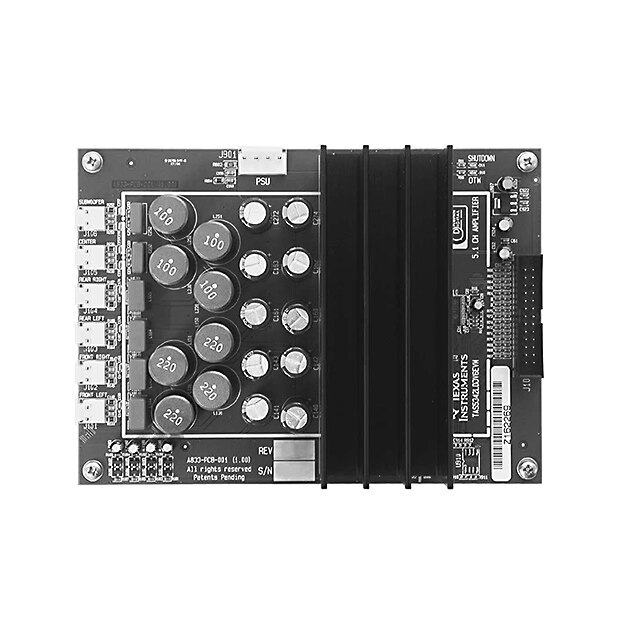
www.ti.com Overview 1 Overview TheTAS5713EVMevaluationmoduledemonstratestheTAS5713devicefromTexasInstruments.The TAS5713combinesahigh-performancePWMprocessorwithaclass-Daudiopoweramplifier.ThisEVM canbeconfiguredwithtwobridge-tiedloads(BTL)(2.0).FordetailedinformationabouttheTAS5713EVM device,reviewthe(devicedatasheetSLOS637).ThePulseWidthModulator(PWM)isbasedonTI's Equibit™technology.TheTAS5713hasadditionalaudioprocessingfeatureslike3D,BassBoostand 2-bandDRC. TheEVMsoftware,withitsgraphicuserinterface(GUI),facilitatesevaluationbyprovidingaccesstothe TAS5713EVMregistersthroughaUSBport.SeetheUsingtheEVMSoftwaresectionforfurtherdetails. Figure1.TAS5713EVMPrinted-CircuitBoard TheEVMtogetherwithotherTIcomponentsonthisboard,isacomplete2.1-channeldigitalaudio amplifiersystem.TheMC57XXPSIAControllerboardincludesaUSBinterface,adigitalinput(SPDIF), analoginputsviatheADC,powerinputs,andotherfeatureslikeamutefunctionandpowerdown. Left MC57xxPSIA TAS5713 EVM PC Interface Right SPDIF/ TAS5713 Optical, Coax 2CHAnalog Input From Other Source/ Digital Out B0340-01 Figure2.CompleteSystemandEVMSignalPathOverview SLOU281–January2010 25WDigitalInputAmplifierWithEQand2-BandDRC 3 SubmitDocumentationFeedback Copyright©2010,TexasInstrumentsIncorporated
Installation www.ti.com 1.1 TAS5713EVM and MC57xxPSIA Features • Channelevaluationmoduledesign • Self-containedprotectionsystemsandcontrolpins • USBinterface • StandardI2Sdatainputusingopticalorcoaxialinputs • Analoginputthroughanalog-to-digitalconverter • Subwooferconnection—thePWMterminalprovidesthePWMsignalandpowertoanexternal subwooferboard • Double-sided,plated-throughPCB,1ozcopper,2mm • AccesstocontrolsignalgainanddataformatthroughEVM-softwareGUI 2 Installation ThissectiondescribestheEVMandsoftwareinstallation. 2.1 EVM Installation MC57xxPSIA Analog In toADC Controller Board 5V Supply for System Power Coaxial SPDIF Input Speaker OutA& B Optical SPDIF Input Speaker Out C & D USB Port 8V–26V Supply for Output Power Figure3.GeneralConnectionPicture ThefollowingarethebasictoolsfortheinitialEVMpowerup. • 5V,1Apowersupply(VIN) • 8–26V,4Apowersupply(PVDD) • Banana-plugtestleadsforpowersuppliesandspeakers • OpticalorcoaxialcableforSPDIFinterfacebasedonsignalsource • USBcable • EVMsoftware • Two8Ω speakersorloads 4 25WDigitalInputAmplifierWithEQand2-BandDRC SLOU281–January2010 SubmitDocumentationFeedback Copyright©2010,TexasInstrumentsIncorporated
www.ti.com Installation ThefollowingsectionsdescribetheTAS5713EVMboardinregardstopowersupply(PSU)andsystem interfaces. 2.1.1 ConnectingtheTAS5713EVMtoMC57xxPSIA OntherightsideoftheMC57xxPSIAisaterminalblockandanotherontheleftoftheTAS5713EVM (labeledJ1).CarefullyplacetheMC57xxPSIAblockabovetheTAS5713EVMblockandgentlypushdown. Figure4.ConnectingTAS5713EVMtoMC57xxPSIA SLOU281–January2010 25WDigitalInputAmplifierWithEQand2-BandDRC 5 SubmitDocumentationFeedback Copyright©2010,TexasInstrumentsIncorporated
Installation www.ti.com 2.1.2 PSUInterface TheTAS5713EVMispoweredbytwopowersuppliesconnectedtotheMC57xxcontrollerboard:a5V powersupply(VIN),anda8V-to-26V(PVDD)powersupply.The3.3Vlevelisgeneratedfromthe5V supplybyanon-boardvoltageregulator. NOTE: Thepower-supplycablelengthmustbeminimized.IncreasingthelengthofthePSUcable increasesthedistortionoftheamplifierathighoutputlevelsandlowfrequencies. Themaximumoutput-stagesupplyvoltagedependsonthespeakerloadresistance.Seethe recommendedmaximumsupplyvoltageintheTAS5713EVMdatasheet. Table1.RecommendedPowerSupplies Description VoltageLimitations(8-ΩLoad) CurrentRecommendations Systempowersupply 5V 1A Outputpowerstagesupply 8–26V 4A(1) (1) Theratedcurrentcorrespondstotwochannels,fullscale. 2.1.3 LoudspeakerConnectors CAUTION All speaker outputs are biased at Vcc/2 and must not be connected to ground (e.g.,throughanoscilloscopeground). Loudspeakerconnectionsvarybydevicesetup.WhenconnectingaspeakerinBTLmode,connectthe speaker’stwoterminals(AandBorCandD)acrosstwooutputsontheTAS5713EVM. SpeakersorloadscanbeconnectedtotheoutputsA-Dwithclipleads,orcablescanbemade withfemaleconnectors(JSTVHR-2N)thatcanmatetomaleconnectorsontheEVMboard. OUTA + OUT B – Figure5.BTLConnection 2.1.4 USBInterface TheTAS5713registersareaccessedthroughI2C™buslinesSDAandSCL.TheUSBcircuitandUSB connectorontheMC57xxPSIAboardfacilitatestheconnectionbetweenahostcomputerandthedevice. TheEVMUSBcircuitispoweredbythe5VUSBlineofthehostPCandisindependentofthepower suppliesavailableontheboard.TheUSBdevicethatisusedisaTAS1020BfromTexasInstruments. 2.1.5 DigitalAudioInterfaceSPDIF TheDigitalAudioInterfaceSPDIF(RCA/OPTO)acceptsdigitalaudiodatausingtheI2Sprotocol.Seethe TAS5713datasheetformoreinformation. TheRCAconnectorandtheOPTOconnectorarethetwoSPDIFinterfacesontheMC57xxPSIAboard. 6 25WDigitalInputAmplifierWithEQand2-BandDRC SLOU281–January2010 SubmitDocumentationFeedback Copyright©2010,TexasInstrumentsIncorporated
www.ti.com Installation TheswitchS3togglesbetweentheOPTOandRCAconnectortoaccommodatethesignalsource.When theRCAcableoropticalcableisconnectedandthesignalsourceispoweredup,verifythattheSPDIF lockindicator(blueLED5)illuminates,confirmingthataviablesignalisavailabletothedevice.Installa jumperonJP4acrossthemiddlepinandthepinmarkedSPDIFtoconnectthedigitalsourcetoSDIN1. InstallajumperonJP5toconnectthedigitalsourcetoSDIN2. FordetailedinformationonhowthedataandclocksareprovidedtotheTAS5713,seetheschematic appearingattheendofthisdocumentandtheDIR9001devicedatasheet(SLES198). 2.1.6 ADCInterface Intheabsenceofadigitalsignalsource,thePCM1808ADCcanbeusedtoconvertananalogaudio signaltoadigitalsignaltotheTAS5713.TheDIR9001stillprovidesclocksignalstotheADCinthis process.A12MHzcrystalisinstalledontheMC57xxPSIAboard.TheADCisanadditionalfeatureofthis boardtoprovideflexibilityinsourcinganaudiosignaltotheTAS5713.ReviewthePCM1808datasheet (SLES177)foradetaileddescriptionoftheADConthisEVM.InstallthejumperonJP4acrossthemiddle pinandthepinmarkedADCtoselectADCasthesourceforSDIN1. 2.1.7 BoardPower-UpGeneralGuidelines ConnecttheMC-57xxandtheTAS5713EVMboardsbylocatingpin1oneachboard,indicatedbyasmall whitetriangle.TheMC-57xxplugsdownontotheTAS5713EVMboard(i.e.,theTAS5713EVMboardfits underneaththeMC57xxPSIAboard).Pin1oneachboardmustbeconnectedtoeachother. InstalltheEVMsoftwareonthePCbeforepoweringuptheboard.Afterconnectingtheloudspeakersor otherloads,powersupplies,andthedataline,powerupthe5Vpowersupplyfirst;thenpowerupthe PVDDpowersupply.ItisrecommendedinitiallytosetthePVDDlevelto10V,thenrampitupto20Vto verifycableconnections. 2.2 Software Installation DownloadtheTAS570xGDEfromtheTIWebsite.TheTIWebsitealwayshasthelatestreleaseandany updatestoversionsoftheGUI. ExecutetheGUIinstallprogram,Setup.exe.Oncetheprogramisinstalled,theprogramgroupand shortcuticoniscreatedinStart→Program →TexasInstrumentsInc→TAS570XGDE.TheGUI launchesasshowninFigure7. Selecttheappropriatetab;inthiscase,selectTAS5713tab.Ithastwosubwindows.Oneshowsthe ProcessFlowwindow.FromtheProcessFlowwindow,eachofthesignal-processingfunctiontoolscan beselectedbyclickingonit.TheBiquadGUIandtheDRCGUIcanbeopenedbyright-clicking.This windowalsoshowsInputselect,Modeselect,Channel,andMasterVolume.Allfunctionsareshowninthe sameorderasinthedevice. Theothersubwindow,Propertieswindow,hasthepropertiesthatausercanupdatebyselectingfromthe availableoptions.Thepropertiesavailabledependonthedeviceselected.Fromthemainwindow,the usermustsetthreepropertiesbeforeconnectingtotheEVM. SLOU281–January2010 25WDigitalInputAmplifierWithEQand2-BandDRC 7 SubmitDocumentationFeedback Copyright©2010,TexasInstrumentsIncorporated
Installation www.ti.com I2C Subaddress in Red 0x72 R 0x70 2BQ + 7BQ 58, 59 Vol1 29–2F 0x73 0x71 DRC 0x46[0] L 0x76 0x74 v2im1 Vol2 2BQ + 7BQ 5C, 5D 30–36 I2C:57 I2C:56 0x77 0x75 VDISTB VDISTA 2BQ 5E, 5F Vol DRC 0x46[1] Vol 2BQ 5A, 5B B0321-09 Figure6.ProcessFlowforTAS5707UG Figure7.MainGUIDisplay 8 25WDigitalInputAmplifierWithEQand2-BandDRC SLOU281–January2010 SubmitDocumentationFeedback Copyright©2010,TexasInstrumentsIncorporated
www.ti.com UsingtheEVMSoftware 3 Using the EVM Software 3.1 Connect the GUI to the EVM OpentheGUI.Selectthepropertieswindow:1-bandor2-bandDRCandStereoorWoofer.Stereois selectedforBTLandWooferisselectedforPBTLMode. Thissendstheinitializationcommandstothedevice.Mastervolumeisinmute.Selectthemastervolume function.Typetherequiredvolumeinthepropertieswindow.Atthistime,audio,ifconnectedproperly, playsthroughthedevice.TheAllchannelshutdownbuttonmustbeun-checked.WhentheConnect commandisissued,ifanerrorappearsindicatingaUSBproblem,checktheconnections,andpressthe USBRESETbuttononthecontrollerboard.Thendisconnectandre-connectfromtheTargetmenu. 3.2 I2C Memory Tool ThistoolcanbeopenedfromGDE(Tools→I2CMemoryTool)orindependentofGDEfromStart→ Program→TexasInstrumentsInc→MemoryTool. SelectI2CasshowinFigure8. Figure8.MemoryToolWindow I2Cregisterscanbewrittenorreadusingthistool.TheI2Ccommandfilecanbesentbyselectingthe commandfileandExecutecommand. SLOU281–January2010 25WDigitalInputAmplifierWithEQand2-BandDRC 9 SubmitDocumentationFeedback Copyright©2010,TexasInstrumentsIncorporated
UsingtheEVMSoftware www.ti.com 3.3 Volume Function TheIndividualandMastervolumecanbeselected,andtherequiredvolumevaluecanbeenteredinthe propertyWindowafterselectingthefunctionwiththemouse(seeFigure9). Figure9.VolumeControl 3.4 Biquad GUI Usingtherightbuttonofmouse,selectBiquadGUI(Figure10). Figure10.SelectingBiquadGUI 10 25WDigitalInputAmplifierWithEQand2-BandDRC SLOU281–January2010 SubmitDocumentationFeedback Copyright©2010,TexasInstrumentsIncorporated
www.ti.com UsingtheEVMSoftware Figure11.FilterCreationToolWindow AcheckmarkselectstheBiquad.Ifnotselected,theBiquadisinALLPASSMode. ThefrequencyresponseforthecurrentsettingscanbeviewedandadjustedinFrequencyResponse WindowTab(Figure11).TheindividualBiquadgainsmustbewithin±12db. Applyfromthefilterdatawindowsendsallthethreebanksofcoefficients(providingautobankis enabled). 3.5 DRC GUI TheTAS5713supports1-bandand2-bandDRC.Selectthedrcmodefrompropertieswindow.Thenset theDRCthresholdbyopeningthedrcguiandadjustingtheslidersasshowninFigure12. Figure12.DRCOptions SLOU281–January2010 25WDigitalInputAmplifierWithEQand2-BandDRC 11 SubmitDocumentationFeedback Copyright©2010,TexasInstrumentsIncorporated
UsingtheEVMSoftware www.ti.com Thecrossoverfrequencyforthe2-bandDRCbydefaultis300Hz.Thiscanbemodifiedbyenteringanew valueinthepropertywindow. PBTLMode:TorunthedeviceinPBTLMode,thePBTLpinmustbedrivenhigh.ThenintheGUI,select wooferinsteadofstereo(stereoisthedefaultvalue).ThesourceforPBTLisselectedas(L+R)/2,butthat bechangedbyupdatinginputmixervalues. 3.5.1 MODULATIONSCHEMES UsingTheFAULTPINAsAnErrorIndicator: TheA_SEL_FAULTZpinistheI2Cdeviceaddressselectbydefault.Tore-definethispinasanoutput, write'1'tobitD1ofreg0X05.Oncere-programmedasoutput,thispinindicatesafaultcondition.Output willgolowforOvercurrent(OC)orundervoltage(UVP)errororovertemperatureerror(OTE)or overvoltageerror CommonConfigurations: 1. 2× BTLBDMode 2. 2× BTLADMode Note: AD: ADModulation-Outputsare180°outofphase BD: BDModulation BTL: Bridge-TiedLoad 3.5.1.1 2XBTLBD(BDmode) 1. Setupthehardware. 2. SelecttheInputMUXfromGDE.Inthepropertieswindow,selectBDMode. 3. GDE:Target> Connect. 4. FinallyunchecktheshutdownboxtobringthedeviceoutofShutdownmode,andadjusttheMaster Volumeasdesired. 3.5.1.2 2XBTLAD(Default:ADmode) 1. Setupthehardware. 2. SelecttheInputMUXfromGDE.Inthepropertieswindow,selectADMode. 3. GDE:Target> Connect. 4. FinallyunchecktheshutdownboxtobringthedeviceoutofShutdownmode,andadjusttheMaster Volumeasdesired. 12 25WDigitalInputAmplifierWithEQand2-BandDRC SLOU281–January2010 SubmitDocumentationFeedback Copyright©2010,TexasInstrumentsIncorporated
www.ti.com JumpersandControlUtilitiesonMC57xxPSIAboard 4 Jumpers and Control Utilities on MC57xxPSIA board 4.1 RCA/OPTICAL Jumpers SelectthejumpertoreflectthesourcewhetheritisRCAorOPTICAL. 4.2 Switches JP1onthedaughtercardisforPBTLselect.JumperINmeansnon-PBTLmode.ForPBTL,removethis jumper. Resetisanactive-lowfunction.Pressingthemasterresetswitch(S2)resetstheTAS5713device;USB RESET(S1)resetstheUSBbus.PressingPDNZ(S4)powersdowntheTAS5713,andpressingMUTE (S5)mutes(volumemute)theTAS5713. 4.3 LED Indicators LED1:USBPowerconnectorinstalledatJ1 LED2:3.3VPowerisvalid LED3:RCAconnectionmade LED4:Opticalconnectionmade LED5:SPDIFsignallocked LED6:FAULT(ThisLEDshouldbeignoreduntilFAULTisprogrammedtobeanoutputviaI2Cwrite toreg0X05.) LED7:PDNswitch(S4)ispressed(closed) SLOU281–January2010 25WDigitalInputAmplifierWithEQand2-BandDRC 13 SubmitDocumentationFeedback Copyright©2010,TexasInstrumentsIncorporated
BoardLayouts,BillofMaterials,andSchematic www.ti.com 5 Board Layouts, Bill of Materials, and Schematic 5.1 TAS5713EVM and MC57xxPSIA Board Layouts Figure13.TAS5713EVMTopCompositeAssembly Figure14.TAS5713EVMTopCopperAssembly 14 25WDigitalInputAmplifierWithEQand2-BandDRC SLOU281–January2010 SubmitDocumentationFeedback Copyright©2010,TexasInstrumentsIncorporated
www.ti.com BoardLayouts,BillofMaterials,andSchematic Figure15.MC57xxPSIATopAssembly SLOU281–January2010 25WDigitalInputAmplifierWithEQand2-BandDRC 15 SubmitDocumentationFeedback Copyright©2010,TexasInstrumentsIncorporated
BoardLayouts,BillofMaterials,andSchematic www.ti.com 5.2 Bill of Materials Table2.BillofMaterialsforTAS5713EVM MANUPartNo. QTY REFDES Vendor Description Vendor MANU PartNo. TI-SEMICONDUCTORS TAS5713PHP 1 U1 TAS5713PHP 15WDIGAMPWITHDAPHTQFP48-PHPROHS Texas TexasInstruments Instruments CAPACITORS GRM188R71H222KA01D 1 C14 490-1500-1 CAPSMD0603CERM2200PFD50V10%X7RROHS Digi-Key Murata ECJ-1VB1H472K 2 C10,C13 PCC1780CT CAPSMD0603CERM4700PFD50V10%X7RROHS Digi-Key Panasonic GRM188R71H103MA01D 4 C28,C30,C32, 490-1511-1 CAPSMD0603CERM0.01UFD50V20%X7RROHS Digi-Key Murata C34 ECJ-1VB1E473K 4 C9,C16,C19,C21 PCC2284CT CAPSMD0603CERM0.033UFD50V10%X7RROHS Digi-Key Panasonic ECJ-1VB1H333K 2 C11,C13 PCC1771CT CAPSMD0603CERM047UFD25V10%X7RROHS Digi-Key Panasonic ECJ-1VB1C104K 4 C2,C4,C6,C7 PCC1762CT CAPSMD0603CERM0.1UFD16V10%X7RROHS Digi-Key Panasonic ECJ-1VB1H104K 8 C17,C20,C22, PCC2398CT CAPSMD0603CERM0.1UFD50V10%X7RROHS Digi-Key Panasonic C23,C27,C29, C31,C33 C1206C684K5RACTU 2 C25,C26 399-3500-1 CAPSMD1206CERM0.68UFD50V10%X7RROHS Digi-Key Kemet TMK107BJ105KA 2 C8,C15 587-1248-1 CAPSMD0603CERM0.1UFD25V10%X5RROHS Digi-Key TaiyoYuden C1680X5R0J475M 1 C3 445-1417-1 CAPSMD603CERM4.7UFD6.3V20%X5RROHS Digi-Key TDK EEE1CA100SR 2 C1,C5 PCE3878CT CAPSMDELECT10UFD16V20%VS-BROHS Digi-Key Panasonic ECA-1VM101 1 C35 P5165 CAPALUMELECMRADIAL100UFD35V20%ROHS Digi-Key Panasonic EC-1VM221BJ 2 C18,C24 P10419TB CAPALUMELECMRADIAL200UFD35V20%ROHS Digi-Key Panasonic RESISTORS ERJ-3GEY0R00V 1 R3 P0.0GCT RESISTORSMD06030.0OHM5%THICKFILM1/10W Digi-Key Panasonic ROHS ERJ-3GEYJ3R3V 4 R11,R12,R13, P3.3GCT RESISTORSMD06033.3OHM5%1/10WROHS Digi-Key Panasonic R14 ERJ-3GEYJ471V 2 R8,R9 P470GCT RESISTORSMD0603470OHM5%1/10WROHS Digi-Key Panasonic ERJ-3EKF1002V 3 R4,R6,R7 P10.0KHCT RESISTORSMD060310.01%THICKFILM1/10WROHS Digi-Key Panasonic RC0603FR-0718K2L 1 R5 311-18.2KHCT RESISTORsmd0603THICKFILM18.2K1%1/10WSMD Digi-Key Yageo 0603 ERJ-3GEYJ104V 1 R2 P100KGCT RESISTORAMD0603100KKOHM5%THICKFILM1/10W Digi-Key Panasonic ROHS INDUCTORS A7503AY-150M 4 L1–L4 A7503AY-150M INDUCTORSERIES11RHBP/A7503AY,15UH/3.5AROHS Toko Toko HEADERSANDJACKS PBC09DAAN 1 J1 S2011E-09 HEADERTHRUMALE,2X9100LSGOLDROHS Digi-Key Sullins PBC02SAAN 1 JP1 S1011E-02 HEADERTHRUMALE,2PIN100LSGOLDROHS Digi-Key Sullins B2PS-VH(LF)(SN) 2 J2,J3 455-1255 JACKJST-VHRA2-PIN3.96mmLSROHS Digi-Key JST SHUNTS SPC02SYAN 1 JP1 S9001 SHUNT,BLACKAUFLASH0.100LS Digi-Key Sullins STANDOFFSANDHARDWARE 2027 4 NA 2027K StandofF,4-40,0.5IN3/16IN,DIAALUMRNDF-F Digi-Key Keystone PMS4400025PH 4 NA H342 4-40Screw,Steel0.250IN Digi-Key BuildingFasteners ComponentCount: 65 COMPONENTSNOTASSEMBLED R1,R10 16 25WDigitalInputAmplifierWithEQand2-BandDRC SLOU281–January2010 SubmitDocumentationFeedback Copyright©2010,TexasInstrumentsIncorporated
www.ti.com BoardLayouts,BillofMaterials,andSchematic 5.3 Schematics TheschematicforTAS5713EVMfollows.TheschematicsforMC57xxPSIAappearonthefollowingpages. 2 3 J J AB CD 12 12 R113.30603 C28 0.01ufd/50V0603 PGND R123.30603 C30 0.01ufd/50V0603 PGND R133.30603 C32 0.01ufd/50V0603 PGND R143.30603 C340.01ufd/50V0603 PGND C27 0.1ufd/50V0603 PGND C29 0.1ufd/50V0603 PGND C31 0.1ufd/50V0603 PGND C33 0.1ufd/50V0603 PGND C25 0.68ufd/50V1206 C26 0.68ufd/50V1206 L1 15uH/3.5AA7503AY L2 15uH/3.5AA7503AY L3 15uH/3.5AA7503AY L4 15uH/3.5AA7503AY PVDD+C18 220ufd/35VM PGND PVDD+C24 220ufd/35VM PGND C17 0.1ufd/50V0603 PGND PVDDC20 0.1ufd/50V0603 PGND PVDDC22 0.1ufd/50V0603 PGND C23 0.1ufd/50V0603 PGND C19 0.033ufd/50V0603 C21 0.033ufd/50V0603 4847 PGND46 4544 43 42 4140 39 3837 PGND R10 DNP0603PGNDC14 2200pfd/50V0603PGNDC15 1.0ufd/25V0603PGND C16 0.033ufd/50V0603 PHP 3433323635C9 0.033ufd/50VC80603 1.0ufd/25V0603 PGND U1PowerPad PGND AVDD R710.0KJP1060312 PGND AVSSC10C12 4700pfd/50V4700pfd/50V06030603C11C13R8R9 470470.047ufd/25.047ufd/25VV0603060306030603 712111086543219 U1TAS5713HTQFP48-PHP 28262531302927C7PGND0.1ufd/16V0603PGND +C6C5 0.1ufd/16V10ufd/16V0603VS-B PGNDPGND AVDD 13+C2C1 0.1ufd/16V10ufd/16V0603VS-BR3 0.00603PGNDAVSS14 15R4 10.0K0603PGNDR51618.2K060317PGND PGND18C3C4 4.7ufd/6.0.1ufd/13V6VR606030603AVDD10.0K0603PGNDPGND192021222324 STANDOFFS PGNDPGNDPGNDPGND AVDD R1DNP0603 R2100K0603 PGND MC57xxCONTROLLERBOARDJ1AVDD12345678910111213PVDD1415161718 PGND +C35 100ufd/35VM PGND SLOU281–January2010 25WDigitalInputAmplifierWithEQand2-BandDRC 17 SubmitDocumentationFeedback Copyright©2010,TexasInstrumentsIncorporated
BoardLayouts,BillofMaterials,andSchematic www.ti.com Y L D N R ON O M BOA TI EV A O U T L A V E G N RI E E N GI N E B F P U3 S1020B A T G N PLI U O C E D T E S E R B S U E C A M F O R R P E E T OT SB IN USB BO DEFAULT) SB I/O N U U A0 I ( 18 25WDigitalInputAmplifierWithEQand2-BandDRC SLOU281–January2010 SubmitDocumentationFeedback Copyright©2010,TexasInstrumentsIncorporated
www.ti.com BoardLayouts,BillofMaterials,andSchematic Y TION ONL SPDIFLOCK TOADC TOEVM BOARD A U L A V E G N RI E E N ENGI FMT0H UPLING MT1H ECO F D F DATAFORMAT24Bit/MSB/I2S SPDI D R A O W VM B PDIF DC U5 R9001P TO E TO S TOA DI JP1 IN: SCKO = 512 FsJP1 OUT: SCKO = 256 Fs(DEFAULT) A @1 V RCAINPUT(LOW) PTO INPUT(HIGH) 3.3 O C D A O T R E T V E EI ES R C R T DIF RE DIF INPUT SPDIFINPUTSELECTOPTO INPUTRCAINPUT MASTE POWER INPU SP SP 1-2:2-3: 5V SLOU281–January2010 25WDigitalInputAmplifierWithEQand2-BandDRC 19 SubmitDocumentationFeedback Copyright©2010,TexasInstrumentsIncorporated
BoardLayouts,BillofMaterials,andSchematic www.ti.com Y L N O ON ARDS EVALUATI TO EVM BO G N RI E E N GI N E PSIA(2-3) MC012(1-2) FAULT PDN MUTE (SDIN1) (SDIN2) NG PLI U O C E D V 5 W P ADC PCM1808 UPLING O C E D V 3.3 CTOR I/O NOTES ON JUMPERSIN: LIN/RIN = 1Vrms MAX.OUT: LIN/RIN = 2Vrms MAX. E N T U N P DC / CO ANALOG INPUTS FROMSPDIF FROM USB FROMMASETER RESET FROM VR1 HIGH POWER IN A 20 25WDigitalInputAmplifierWithEQand2-BandDRC SLOU281–January2010 SubmitDocumentationFeedback Copyright©2010,TexasInstrumentsIncorporated
EVALUATIONBOARD/KITIMPORTANTNOTICE TexasInstruments(TI)providestheenclosedproduct(s)underthefollowingconditions: Thisevaluationboard/kitisintendedforuseforENGINEERINGDEVELOPMENT,DEMONSTRATION,OREVALUATIONPURPOSES ONLYandisnotconsideredbyTItobeafinishedend-productfitforgeneralconsumeruse.Personshandlingtheproduct(s)musthave electronicstrainingandobservegoodengineeringpracticestandards.Assuch,thegoodsbeingprovidedarenotintendedtobecomplete intermsofrequireddesign-,marketing-,and/ormanufacturing-relatedprotectiveconsiderations,includingproductsafetyandenvironmental measurestypicallyfoundinendproductsthatincorporatesuchsemiconductorcomponentsorcircuitboards.Thisevaluationboard/kitdoes notfallwithinthescopeoftheEuropeanUniondirectivesregardingelectromagneticcompatibility,restrictedsubstances(RoHS),recycling (WEEE),FCC,CEorUL,andthereforemaynotmeetthetechnicalrequirementsofthesedirectivesorotherrelateddirectives. Shouldthisevaluationboard/kitnotmeetthespecificationsindicatedintheUser’sGuide,theboard/kitmaybereturnedwithin30daysfrom thedateofdeliveryforafullrefund.THEFOREGOINGWARRANTYISTHEEXCLUSIVEWARRANTYMADEBYSELLERTOBUYER ANDISINLIEUOFALLOTHERWARRANTIES,EXPRESSED,IMPLIED,ORSTATUTORY,INCLUDINGANYWARRANTYOF MERCHANTABILITYORFITNESSFORANYPARTICULARPURPOSE. Theuserassumesallresponsibilityandliabilityforproperandsafehandlingofthegoods.Further,theuserindemnifiesTIfromallclaims arisingfromthehandlingoruseofthegoods.Duetotheopenconstructionoftheproduct,itistheuser’sresponsibilitytotakeanyandall appropriateprecautionswithregardtoelectrostaticdischarge. EXCEPTTOTHEEXTENTOFTHEINDEMNITYSETFORTHABOVE,NEITHERPARTYSHALLBELIABLETOTHEOTHERFORANY INDIRECT,SPECIAL,INCIDENTAL,ORCONSEQUENTIALDAMAGES. TIcurrentlydealswithavarietyofcustomersforproducts,andthereforeourarrangementwiththeuserisnotexclusive. TIassumesnoliabilityforapplicationsassistance,customerproductdesign,softwareperformance,orinfringementofpatentsor servicesdescribedherein. PleasereadtheUser’sGuideand,specifically,theWarningsandRestrictionsnoticeintheUser’sGuidepriortohandlingtheproduct.This noticecontainsimportantsafetyinformationabouttemperaturesandvoltages.ForadditionalinformationonTI’senvironmentaland/or safetyprograms,pleasecontacttheTIapplicationengineerorvisitwww.ti.com/esh. NolicenseisgrantedunderanypatentrightorotherintellectualpropertyrightofTIcoveringorrelatingtoanymachine,process,or combinationinwhichsuchTIproductsorservicesmightbeorareused. FCCWarning Thisevaluationboard/kitisintendedforuseforENGINEERINGDEVELOPMENT,DEMONSTRATION,OREVALUATIONPURPOSES ONLYandisnotconsideredbyTItobeafinishedend-productfitforgeneralconsumeruse.Itgenerates,uses,andcanradiateradio frequencyenergyandhasnotbeentestedforcompliancewiththelimitsofcomputingdevicespursuanttopart15ofFCCrules,whichare designedtoprovidereasonableprotectionagainstradiofrequencyinterference.Operationofthisequipmentinotherenvironmentsmay causeinterferencewithradiocommunications,inwhichcasetheuserathisownexpensewillberequiredtotakewhatevermeasuresmay berequiredtocorrectthisinterference. EVMWARNINGSANDRESTRICTIONS ItisimportanttooperatethisEVMwithintheinputvoltagerangeof-0.5Vto4.1Vandtheoutputvoltagerangeof1Vrms. Exceedingthespecifiedinputrangemaycauseunexpectedoperationand/orirreversibledamagetotheEVM.Iftherearequestions concerningtheinputrange,pleasecontactaTIfieldrepresentativepriortoconnectingtheinputpower. Applyingloadsoutsideofthespecifiedoutputrangemayresultinunintendedoperationand/orpossiblepermanentdamagetotheEVM. PleaseconsulttheEVMUser'sGuidepriortoconnectinganyloadtotheEVMoutput.Ifthereisuncertaintyastotheloadspecification, pleasecontactaTIfieldrepresentative. Duringnormaloperation,somecircuitcomponentsmayhavecasetemperaturesgreaterthan85°C.TheEVMisdesignedtooperate properlywithcertaincomponentsabove85°Caslongastheinputandoutputrangesaremaintained.Thesecomponentsincludebutare notlimitedtolinearregulators,switchingtransistors,passtransistors,andcurrentsenseresistors.Thesetypesofdevicescanbeidentified usingtheEVMschematiclocatedintheEVMUser'sGuide.Whenplacingmeasurementprobesnearthesedevicesduringoperation, pleasebeawarethatthesedevicesmaybeverywarmtothetouch. MailingAddress:TexasInstruments,PostOfficeBox655303,Dallas,Texas75265 Copyright©2008-2009,TexasInstrumentsIncorporated
IMPORTANTNOTICE TexasInstrumentsIncorporatedanditssubsidiaries(TI)reservetherighttomakecorrections,modifications,enhancements,improvements, andotherchangestoitsproductsandservicesatanytimeandtodiscontinueanyproductorservicewithoutnotice.Customersshould obtainthelatestrelevantinformationbeforeplacingordersandshouldverifythatsuchinformationiscurrentandcomplete.Allproductsare soldsubjecttoTI’stermsandconditionsofsalesuppliedatthetimeoforderacknowledgment. TIwarrantsperformanceofitshardwareproductstothespecificationsapplicableatthetimeofsaleinaccordancewithTI’sstandard warranty.TestingandotherqualitycontroltechniquesareusedtotheextentTIdeemsnecessarytosupportthiswarranty.Exceptwhere mandatedbygovernmentrequirements,testingofallparametersofeachproductisnotnecessarilyperformed. TIassumesnoliabilityforapplicationsassistanceorcustomerproductdesign.Customersareresponsiblefortheirproductsand applicationsusingTIcomponents.Tominimizetherisksassociatedwithcustomerproductsandapplications,customersshouldprovide adequatedesignandoperatingsafeguards. TIdoesnotwarrantorrepresentthatanylicense,eitherexpressorimplied,isgrantedunderanyTIpatentright,copyright,maskworkright, orotherTIintellectualpropertyrightrelatingtoanycombination,machine,orprocessinwhichTIproductsorservicesareused.Information publishedbyTIregardingthird-partyproductsorservicesdoesnotconstitutealicensefromTItousesuchproductsorservicesora warrantyorendorsementthereof.Useofsuchinformationmayrequirealicensefromathirdpartyunderthepatentsorotherintellectual propertyofthethirdparty,oralicensefromTIunderthepatentsorotherintellectualpropertyofTI. ReproductionofTIinformationinTIdatabooksordatasheetsispermissibleonlyifreproductioniswithoutalterationandisaccompanied byallassociatedwarranties,conditions,limitations,andnotices.Reproductionofthisinformationwithalterationisanunfairanddeceptive businesspractice.TIisnotresponsibleorliableforsuchaltereddocumentation.Informationofthirdpartiesmaybesubjecttoadditional restrictions. ResaleofTIproductsorserviceswithstatementsdifferentfromorbeyondtheparametersstatedbyTIforthatproductorservicevoidsall expressandanyimpliedwarrantiesfortheassociatedTIproductorserviceandisanunfairanddeceptivebusinesspractice.TIisnot responsibleorliableforanysuchstatements. TIproductsarenotauthorizedforuseinsafety-criticalapplications(suchaslifesupport)whereafailureoftheTIproductwouldreasonably beexpectedtocauseseverepersonalinjuryordeath,unlessofficersofthepartieshaveexecutedanagreementspecificallygoverning suchuse.Buyersrepresentthattheyhaveallnecessaryexpertiseinthesafetyandregulatoryramificationsoftheirapplications,and acknowledgeandagreethattheyaresolelyresponsibleforalllegal,regulatoryandsafety-relatedrequirementsconcerningtheirproducts andanyuseofTIproductsinsuchsafety-criticalapplications,notwithstandinganyapplications-relatedinformationorsupportthatmaybe providedbyTI.Further,BuyersmustfullyindemnifyTIanditsrepresentativesagainstanydamagesarisingoutoftheuseofTIproductsin suchsafety-criticalapplications. TIproductsareneitherdesignednorintendedforuseinmilitary/aerospaceapplicationsorenvironmentsunlesstheTIproductsare specificallydesignatedbyTIasmilitary-gradeor"enhancedplastic."OnlyproductsdesignatedbyTIasmilitary-grademeetmilitary specifications.BuyersacknowledgeandagreethatanysuchuseofTIproductswhichTIhasnotdesignatedasmilitary-gradeissolelyat theBuyer'srisk,andthattheyaresolelyresponsibleforcompliancewithalllegalandregulatoryrequirementsinconnectionwithsuchuse. TIproductsareneitherdesignednorintendedforuseinautomotiveapplicationsorenvironmentsunlessthespecificTIproductsare designatedbyTIascompliantwithISO/TS16949requirements.Buyersacknowledgeandagreethat,iftheyuseanynon-designated productsinautomotiveapplications,TIwillnotberesponsibleforanyfailuretomeetsuchrequirements. FollowingareURLswhereyoucanobtaininformationonotherTexasInstrumentsproductsandapplicationsolutions: Products Applications Amplifiers amplifier.ti.com Audio www.ti.com/audio DataConverters dataconverter.ti.com Automotive www.ti.com/automotive DLP®Products www.dlp.com Broadband www.ti.com/broadband DSP dsp.ti.com DigitalControl www.ti.com/digitalcontrol ClocksandTimers www.ti.com/clocks Medical www.ti.com/medical Interface interface.ti.com Military www.ti.com/military Logic logic.ti.com OpticalNetworking www.ti.com/opticalnetwork PowerMgmt power.ti.com Security www.ti.com/security Microcontrollers microcontroller.ti.com Telephony www.ti.com/telephony RFID www.ti-rfid.com Video&Imaging www.ti.com/video RF/IFandZigBee®Solutions www.ti.com/lprf Wireless www.ti.com/wireless MailingAddress:TexasInstruments,PostOfficeBox655303,Dallas,Texas75265 Copyright©2009,TexasInstrumentsIncorporated