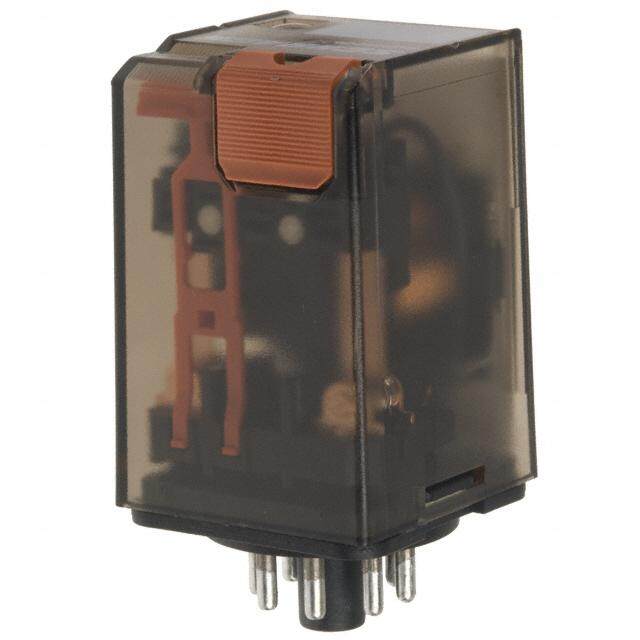
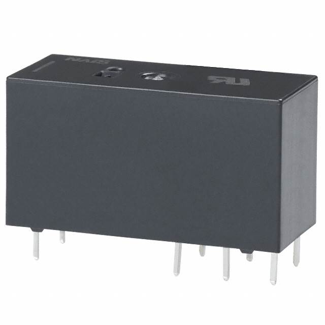
ICGOO在线商城 > 继电器 > 功率继电器,高于 2 A > T9AS1D12-5
- 型号: T9AS1D12-5
- 制造商: CORCOM/TYCO ELECTRONICS
- 库位|库存: xxxx|xxxx
- 要求:
| 数量阶梯 | 香港交货 | 国内含税 |
| +xxxx | $xxxx | ¥xxxx |
查看当月历史价格
查看今年历史价格
T9AS1D12-5产品简介:
ICGOO电子元器件商城为您提供T9AS1D12-5由CORCOM/TYCO ELECTRONICS设计生产,在icgoo商城现货销售,并且可以通过原厂、代理商等渠道进行代购。 T9AS1D12-5价格参考¥24.89-¥24.89。CORCOM/TYCO ELECTRONICST9AS1D12-5封装/规格:功率继电器,高于 2 A, 通用 继电器 SPST-NO(1 Form A) 5VDC 线圈 通孔。您可以下载T9AS1D12-5参考资料、Datasheet数据手册功能说明书,资料中有T9AS1D12-5 详细功能的应用电路图电压和使用方法及教程。
| 参数 | 数值 |
| 3D型号 | http://www.te.com/commerce/DocumentDelivery/DDEController?Action=srchrtrv&DocNm=2-1393210-0&DocType=Customer+View+Model&DocLang=English |
| 产品目录 | |
| 描述 | RELAY GEN PURPOSE SPST 30A 5V通用继电器 SPST-NO 30A 5VDC |
| 产品分类 | |
| 品牌 | TE Connectivity / P&B |
| 产品手册 | |
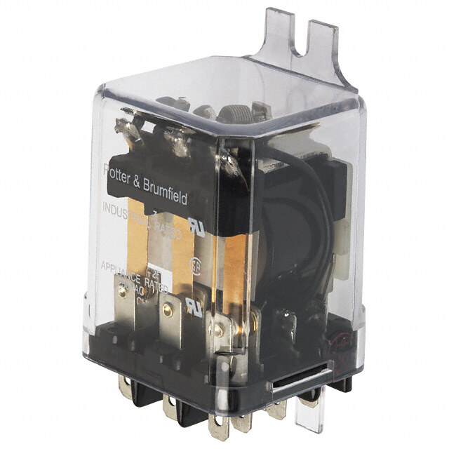
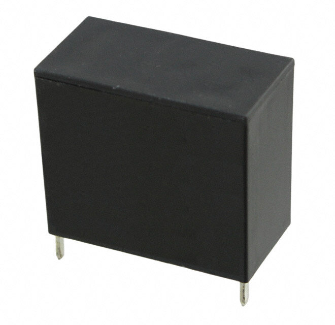
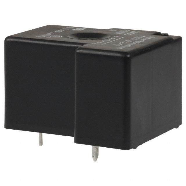
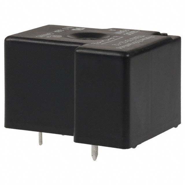
| 产品图片 |
|
| rohs | 符合RoHS无铅 / 符合限制有害物质指令(RoHS)规范要求 |
| 产品系列 | 通用继电器,TE Connectivity / P&B T9AS1D12-5T9A,Potter & Brumfield |
| 数据手册 | |
| 产品型号 | T9AS1D12-5 |
| 产品 | Power Relays |
| 产品目录绘图 |
|
| 产品目录页面 | |
| 产品种类 | 通用继电器 |
| 关闭电压(最小值) | 0.5 VDC |
| 其它名称 | 2-1393210-0 |
| 切换电压 | 277 VAC |
| 功耗 | 1 W |
| 包装 | 散装 |
| 商标 | TE Connectivity / P&B |
| 安装类型 | Flange |
| 安装风格 | Through Hole |
| 宽度 | 27.4 mm |
| 导通电压(最大值) | 3.75 VDC |
| 工作时间 | 15ms |
| 工作温度 | -55°C ~ 85°C |
| 工厂包装数量 | 250 |
| 开关电压 | 277VAC - 最小值 |
| 标准包装 | 50 |
| 特性 | 绝缘 - F 级,密封式 - 全部 |
| 特色产品 | http://www.digikey.com/cn/zh/ph/te/relays.htmlhttp://www.digikey.cn/product-highlights/cn/zh/te-connectivity-t9a-series-relays/3791 |
| 端子类型 | PC 引脚 |
| 端接类型 | Solder Pin |
| 类型 | Standard |
| 系列 | T9A |
| 线圈功率 | 1 W |
| 线圈电压 | 5 VDC |
| 线圈电流 | 200mA |
| 线圈电阻 | 25 Ohms |
| 线圈端接 | Quick Connect Terminal |
| 线圈类型 | Non-Latching |
| 继电器类型 | 通用 |
| 触头外形 | SPST-NO(1 A 型) |
| 触头材料 | 银镉氧化物(AgCdO) |
| 触点形式 | SPST (1 Form A) |
| 触点材料 | Silver Cadmium Oxide |
| 触点电流额定值 | 30 A |
| 触点端接 | Pin |
| 释放时间 | 15ms |
| 长度 | 32.5 mm |
| 零件号别名 | 2-1393210 |
| 额定接触(电流) | 30A |
| 高度 | 27.9 mm |



- 商务部:美国ITC正式对集成电路等产品启动337调查
- 曝三星4nm工艺存在良率问题 高通将骁龙8 Gen1或转产台积电
- 太阳诱电将投资9.5亿元在常州建新厂生产MLCC 预计2023年完工
- 英特尔发布欧洲新工厂建设计划 深化IDM 2.0 战略
- 台积电先进制程称霸业界 有大客户加持明年业绩稳了
- 达到5530亿美元!SIA预计今年全球半导体销售额将创下新高
- 英特尔拟将自动驾驶子公司Mobileye上市 估值或超500亿美元
- 三星加码芯片和SET,合并消费电子和移动部门,撤换高东真等 CEO
- 三星电子宣布重大人事变动 还合并消费电子和移动部门
- 海关总署:前11个月进口集成电路产品价值2.52万亿元 增长14.8%


PDF Datasheet 数据手册内容提取
General Purpose Relays Power Relays Potter & Brumfield T9A Series, DC Coil 30A PCB or Panel Mount Relay n 30A switching in 1 form A (NO) and 20A in 1 form C (CO) n Plastic sealed case available n Meets UL 508 and 873 spacing - 3.18mm through air, 6.36mm over surface n Option for load connections via 0.250”” (6.35mm) Q.C. terminals n UL class F insulation system standard Typical applications HVAC, Appliances, Industrial Controls Approvals UL E58304; CSA LR48471 Technical data of approved types on request Contact Data Contact ratings 1) (continued) Contact arrangement 1 form A (NO), 1 form B (NC), 1 form C (CO) Type Load Cycles Rated voltage 277VAC UL 508/873 Max. switching voltage 277VAC AgSnOInO, 1W coil Rated current 30A 15A 20A/10A NO 30A, 240VAC, general purpose 100x103 Limiting continuous current 30A NO 80LRA/30FLA, 240VAC 30x103 Contact material AgSnOInO, AgCdO NC 10A, 250VAC, resistive 50x103 Min. recommended contact load 1A, 5VDC or 12VAC AgCdO, 900mW coil Initial contact resistance 75 mΩ at 1A at 5VDC or 12VAC NO 30A, 240VAC, general purpose 100x103 Frequency of operation, with/without load 360/3600hr NO 18A, 240VAC, resistive, 105°C 100x103 Operate/release time max., including bounce 15/15ms NC 15A, 240VAC, resistive 6x10³ NO 30LRA/15FLA, 240VAC 100x103 Contact ratings 1) NO 50LRA/16FLA, 120VAC 100x103 Type Load Cycles NO 30LRA/11FLA, 120VAC 200x103 Factory 1) Contact ratings at 25°C (unless otherwise noteed) with relay properly vented. Remove AgCdO, 1W coil vent nib after soldering and cleaning. NO 30A, 240VAC, general purpose 100x103 NO 25A, 240VAC, resistive 100x103 Mechanical endurance 10x106 ops. CO 20A/10A, 240VAC, general purpose 100x103 CO 20A/10A, 240VAC, resistive 100x103 CO 20A/10A, 28VDC, resistive 100x103 Coil Data UL 508/873 Coil voltage range 5 to 110VDC AgCdO, 1W coil Max. coil power 110% of nominal NO 30A, 240VAC, general purpose 100x103 Max. coil temperature 155°C NC 15A, 240VAC, general purpose 100x103 Coil insulation system according UL Class F CO 20A/10A, 240VAC, general purpose 100x103 Coil versions, DC coil NC 20A, 240VAC, resistive 6x10³ Coil Rated Operate Release Coil Rated coil CO 16.75A/13.4A, 240VAC, resistive 6x10³ code voltage voltage voltage resistance power NO 80LRA/30FLA, 240VAC 30x103 VDC VDC VDC Ω±10% W NC 30LRA/12FLA, 240VAC 30x103 Code D (1W) coil CO 53.6LRA/20FLA / 20LRA/8FLA, 240VAC 30x103 5 5 3.75 0.5 25 1 NO 98LRA/22FLA, 120VAC 100x103 6 6 4.5 0.6 36 1 NO 2HP, 240VAC 1x10³ 9 9 6.75 0.9 81 1 NC 1/2HP, 240VAC 1x10³ 12 12 9 1.2 144 1 NO 1HP, 125VAC 1x10³ 15 15 11.25 1.5 225 1 NC 1/4HP, 125VAC 1x10³ 18 18 13.5 1.8 324 1 NO 10A, 277VAC, ballast 6x10³ 24 24 18 2.4 576 1 NC 3A, 277VAC, ballast 6x10³ 48 48 36 4.8 2304 1 NO 8.3A, 120VAC, tungsten 6x10³ 110 110 82.5 11 12100 1 NO 5.4A, 277VAC, tungsten 6x10³ Code L (900mW) coil NO 470VA, 120VAC, pilot duty 30x103 5 5 3.75 0.5 27 .9 NO 20A, 28VDC, resistive 100x103 6 6 4.5 0.6 40 .9 NC 10A, 28VDC, resistive 100x103 9 9 6.75 0.9 97 .9 AgCdO - Enhanced Version Only, 1W coil 12 12 9 1.2 155 .9 NO 21A, 250VAC, resistive 250x103 15 15 11.25 1.5 256 .9 NO 25A, 277VAC, resistive 100x103 18 18 13.5 1.8 380 .9 AgCdO, 1W coil (“H” type) 24 24 18 2.4 660 .9 NO 25A, 240VAC, resistive, 105°C 6x10³ 48 48 36 4.8 2560 .9 1) Contact ratings at 25°C (unless otherwise noteed) with relay properly vented. Remove 110 110 82.5 11 13450 .9 vent nib after soldering and cleaning. All figures are given for coil without preenergization, at ambient temperature +23°C. 1 09-2015, Rev. 0815 Datasheets and product specification Datasheets and product data is subject to the Datasheets, product data, ‘Definitions’ sec- www.te.com according to IEC 61810-1 and to be used terms of the disclaimer and all chapters of tion, application notes and all specifications © 2015 Tyco Electronics Corporation, only together with the ‘Definitions’ section. the ‘Definitions’ section, available at are subject to change. a TE Connectivity Ltd. company http://relays.te.com/definitions
General Purpose Relays Power Relays Potter & Brumfield T9A Series, DC Coil 30A PCB or Panel Mount Relay (Continued) Coil Data (continued) Insulation Data Ambient temperature vs. coil voltage – 1W coil Initial dielectric strength Data below are average values and should be verified in application. Tests between open contacts 1500Vrms were conducted within a 2’ (.6 m) cube (still air); at nominal coil power @ between contact and coil 2500Vrms 25°C; with normally open contact loaded; and with 4’ (1.22 m) long, #10 Initial surge withstand voltage AWG load wires. P.C. board relays were mounted to a 30A, single side P.C. between contact and coil 6kV board. Coil rise test conducted with a 30A PC board to maintain 20°C max. Initial insulation resistance rize at 30°C. The relay connections and wiring must be designed with an between insulated elements 1x10⁹Ω adequate cross section to ensure proper current flow and heat dissipation. Clearance/creepage between contact and coil 3.18mm clearance/6.3638mm 140 120 Other Data C)100 Material compliance: EU RoHS/ELV, China RoHS, REACH, Halogen content ble p. ( refer to the Product Compliance Support Center at Max. Alowa Ambient Tem 468000 Wash-Tight Relay, Vented (2, 10230A00AAA A m DbCie ncto tile mperature www.te.com/cus tome1r0s5u-°p5Cp5 omºrCto/ rtdooe h l8ss5 saºuCvpa p3ila)o brtlcee nter 20 Load Connections Via Q.C. Terminals, Category of environmental protection PC Mount IEC 61810 RT0 - open, RTI - dust protected, 0 60 80 100 120 140 160 180 RTII - flux proof, RTIII - wash tight Applied Coil Voltage (% of Rated Voltage) Vibration resistance (functional) 1.65mm max excursions, 10-55 Hz Shock resistance (functional) 10g for 11msec 140 Shock resistance (destructive) 100g C)120 Terminal type pcb-tht and pcb-tht + quick connect ble p. ( Weight 26g mounting code 1 Max. Alowa Ambient Tem1680000 Dust Protected Relay, 10230A00AAA R Paec IsEiksCatag 6nin0cg0e/6 ut8on- it2s o- 2l d 0 e r i n g h e a t t rTaHy/T50 pc3 s3.g, bmuonudnlet/in2g52 0c5 o0pd°cCess., 2b oaxn/d5 050 pcs. Flange Mount 40 3) Operating ambient temperature must consider “Must Operate Voltage Change Over 60 80 100 120 140 160 180 Temperature,” Contact Temperature Rise, Coil Temperature Rise (If coil is not allowed to Applied Coil Voltage (% of Rated Voltage) cool) and Maximum Coil Temperature. Specification ambient considers 20A load with coil cooled to ambient. 140 120 C)100 x. Alowable ent Temp. ( 6800 0A Ma mbi 40 10A A 20A 20 Wash-Tight Relay, Vented (2 PC Terminals For Coil & Contacts 30A 0 60 80 100 120 140 160 180 Applied Coil Voltage (% of Rated Voltage) 2) Remove knock-off nib after cleaning process for optimum life of wash-tight relays. Dimensions T9AS – Mounting and termination code 2 T9AP – Mounting and termination code 5 .(265.305 x x . 0.8312) C OQNUNICEKCT .(133.300 . 0.5210) (.41.8Q775U xxIC ..0K52008) 1.0(2870. 4M3A)X. 1.1(2070. 9M4A)X. CONNECT Ø.03 (.80) .250 x .032 2 PLACES (6.35 x .81) QUICK M .045 x .045 CONNECT 1.980 MAX. O 1.280 MAX. (1.14 x 1.14) (50.29) C (32.51) M O O 1.713 ± .010 N .(0.8312 xx 1.0.5672) ON C (43.51 ± .25) 1.2(3820. 5M1A)X. C N C N 1.080 MAX. 1.100 MAX. (27.43) (27.94) .071 (1.80) RAD. FOR #6 SCREW Note: Recommended mounting screw torque is 4.0-5.0 lbs.in when #6 screw is used. 2 09-2015, Rev. 0815 Datasheets and product specification Datasheets and product data is subject to the Datasheets, product data, ‘Definitions’ sec- www.te.com according to IEC 61810-1 and to be used terms of the disclaimer and all chapters of tion, application notes and all specifications © 2015 Tyco Electronics Corporation, only together with the ‘Definitions’ section. the ‘Definitions’ section, available at are subject to change. a TE Connectivity Ltd. company http://relays.te.com/definitions
General Purpose Relays Power Relays Potter & Brumfield T9A Series, DC Coil 30A PCB or Panel Mount Relay (Continued) Dimensions Plain case Bracket mount case .805 MAX. (20.4) . 1 3 0 +– ..001106 .21(52. 3M8A)X. .032 x .062 .950 MAX. .6(8107 .M27A)X. .032 x .062 ( 3 . 3 0 + – ..4215) TE(.R8M x IN1.A6L)S (24.13) .130 ± .020 TE(.R8M x IN1.A6L)S (3.3 ± .51) .50 .10 MAX. .69 (12.8) (2.54) (17.6) 1.2(3820. 5M1A)X. 1.20 MAX. (.10.4154 xx .10.4154) .045 x .045 (30.5) TERMINAL (1.14 x 1.14) 1.(0287 .M43A)X. .(0.4136) TEØR M(..08I3N0)ALS TERMINAL TEØR (M0.0.I83N0A)LS Terminal assignment Bottom view on pins Notes: 1) General tolerance 1 Form A 1 Form B 1 Form C Diagram Dimensions Tolerance <1mm ±0.1 1~3mm ±0.2 >3mm ±0.3 2) Dimensions of the pins after tin soldering for PCB type a) +0.2 for the widht and thickness b) +0.5 for the lenght PCB layout Bottom view on pins T9AP/S - Mounting and termination code 2 T9AS/V - Mounting and termination code 1 .14(30. 5M6A)X. .25(60. 3M5A)X. .08(12 .±0 6.0 ±0 5.1 D3)IA. .21(52. 3M8A)X. .08(12 .±0 6.0 ±0 5.1 D3)IA. .300 .100 (.73.0602) (.21.0504) .07(81 .±9 8.0 ±0 3.0 D8)IA. Oprnelsye nnet coens ssainrgy lete trhmroinwal sm aordee ls. (7.62) (2.54) .07(81 .±9 8.0 ±0 3.0 D8)IA. Oprnelsye nnet coens ssainrgy lete trhmroinwal sm aordee ls. Consequently, some holes will .600 Consequently, some holes will (1.650.204) (.1520.07) .04(31 .±0 9.0 ±0 3.0 D8)IA. bmeo udnenlse.cessary for single throw (15.24)(.1520.07) .04(31 .±0 9.0 ±0 3.0 D8)IA. bmeo udnenlse.cessary for single throw .150 (3.81) .150 (3.81) .550 .550 (13.97) (13.97) .700 .700 (17.78) (17.78) Product code structure Typical product code T9A S 5 D 2 2 -12 Type T9A Power PCB or panel mount relay T9A Enclosure N Open, no enclosure (requires mounting code 1) P Dust protected plastic case (requires mounting code 5) S Wash-tight plastic case with knock off nib (requires mounting code 1 or 2) V Flux-proof plastic case (requires mounting code 1 or 2) Contact arrangement 1 1 form A (1 NO) 2 1 form B (1 NC) 5 1 form C (1 CO) Coil Input D DC voltage, 1W L DC voltage, 900mW H1) DC voltage, 1W (+0/-10 percent coil resistance) Mounting and termination 1 PCB mounting; PCB terminals for coil and contacts (only available with enclosure code N, S or V) 2 PCB mounting; PCB term. for coil and contacts; 6.35mm (.250in) QC for contacts (only available with enclosure code N, S or V) 5 Flanged mounting; 4.75mm (.187) QC for coil; 6.35mm (.250in) QC for contacts (only available with enclosure code P) Contact material 2 AgCdO 4 AgSnOInO 7 AgCdO (Enhanced version) Coil voltage Coil code: please refer to coil versions table 1) “H” type coil is only available in mounting termination options 2 & 5. 3 09-2015, Rev. 0815 Datasheets and product specification Datasheets and product data is subject to the Datasheets, product data, ‘Definitions’ sec- www.te.com according to IEC 61810-1 and to be used terms of the disclaimer and all chapters of tion, application notes and all specifications © 2015 Tyco Electronics Corporation, only together with the ‘Definitions’ section. the ‘Definitions’ section, available at are subject to change. a TE Connectivity Ltd. company http://relays.te.com/definitions
General Purpose Relays Power Relays Potter & Brumfield T9A Series, DC Coil 30A PCB or Panel Mount Relay (Continued) Product Code Enclosure Contacts Coil Mounting Contact Material Coil Part Number T9AN1L22-24 Open (no cover) 1 form A, 1 NO 900mW pcb + QC AgCdO 24VDC 1419104-6 T9AN5L12-24 1 form C, 1 CO pcb terminals 1-1393210-0 T9AN5L22-24 pcb + QC 1419104-9 T9AP1D52-12 Unsealed, plastic dust cover 1 form A, 1 NO 1W Flanged mount, QC 12VDC 6-1419102-0 T9AP1D52-24 24VDC 6-1419102-3 T9AP1D52-48 48VDC 5-1419102-8 T9AP1D54-24 AgSnOInO 24VDC 7-1423091-3 T9AP5D52-12 1 form C, 1 CO AgCdO 12VDC 5-1419102-4 T9AP5D52-24 24VDC 5-1419102-2 T9AP5D52-48 48VDC 6-1419102-4 T9AP5D54-12 AgSnOInO 12VDC 7-1423091-4 T9AP5D54-24 24VDC 7-1423091-5 T9AS1D12-5 Wash tight, knock off nib 1 form A, 1 NO pcb terminals AgCdO 5VDC 2-1393210-0 T9AS1D12-9 9VDC 2-1393210-2 T9AS1D12-12 12VDC 1-1393210-3 T9AS1D12-15 15VDC 1-1393210-4 T9AS1D12-18 18VDC 1-1393210-5 T9AS1D12-24 24VDC 1-1393210-8 T9AS1D12-48 48VDC 1-1393210-9 T9AS1D12-110 110VDC 1-1393210-2 T9AS1D14-12 AgSnOInO 12VDC 5-1423091-7 T9AS1D14-24 24VDC 6-1423091-3 T9AS1D22-5 pcb + QC AgCdO 5VDC 2-1419104-3 T9AS1D22-12 12VDC 1-1419104-7 T9AS1D22-24 24VDC 2-1419104-1 T9AS1D22-48 48VDC 2-1419104-2 T9AS1D22-110 110VDC 1-1419104-6 T9AS1L12-12 900mW pcb terminals 12VDC 2-1393210-4 T9AS1L12-24 24VDC 2-1393210-5 T9AS1L22-18 pcb + QC 18VDC 2-1419104-6 T9AS2L22-24 1 form B, 1 NC 24VDC 1423794-1 T9AS5D12-5 1 form C, 1 CO 1W pcb terminals 5VDC 3-1393210-9 T9AS5D12-12 12VDC 3-1393210-3 T9AS5D12-18 18VDC 3-1393210-4 T9AS5D12-24 24VDC 3-1393210-7 T9AS5D12-48 48VDC 3-1393210-8 T9AS5D12-110 110VDC 3-1393210-2 T9AS5D14-5 AgSnOInO 5VDC 6-1423091-4 T9AS5D22-5 pcb + QC AgCdO 3-1419104-9 T9AS5D22-12 12VDC 3-1419104-3 T9AS5D22-24 24VDC 3-1419104-6 T9AS5D22-110 110VDC 3-1419104-2 T9AS5D24-5 AgSnOInO 5VDC 6-1423091-9 T9AS5D24-12 12VDC 7-1423091-0 T9AS5D24-24 24VDC 7-1423091-1 T9AS5L12-12 900mW pcb terminals AgCdO 12VDC 4-1393210-1 T9AS5L22-18 pcb + QC 18VDC 4-1419104-0 T9AS5L22-24 24VDC 4-1419104-1 T9AS5L22-48 48VDC 9-1419136-6 T9AV1D12-12 Vented, flux tight 1 form A, 1 NO 1W pcb terminals 12VDC 4-1393210-3 T9AV1D12-18 18VDC 5-1393210-2 T9AV1D22-18 pcb + QC 4-1419148-8 T9AV1D22-24 24VDC 5-1419148-0 T9AV1D22-48 48VDC 2-1423091-3 T9AV1L12-12 900mW pcb terminals 12VDC 1-1423091-8 T9AV1L22-24 pcb + QC 24VDC 4-1419104-2 T9AV2D22-24 1 form B, 1NC 1W 1419137-1 T9AV5D12-24 1 form C, 1CO pcb terminals 4-1393210-8 T9AV5D22-18 pcb + QC 18VDC 5-1419148-2 T9AV5D22-24 24VDC 1419137-2 T9AV5L12-12 900mW pcb terminals 12VDC 1423091-6 Note. This list represents the most common types and does not show all variants covered by this datasheet. Other types on request. 4 09-2015, Rev. 0815 Datasheets and product specification Datasheets and product data is subject to the Datasheets, product data, ‘Definitions’ sec- www.te.com according to IEC 61810-1 and to be used terms of the disclaimer and all chapters of tion, application notes and all specifications © 2015 Tyco Electronics Corporation, only together with the ‘Definitions’ section. the ‘Definitions’ section, available at are subject to change. a TE Connectivity Ltd. company http://relays.te.com/definitions
 Datasheet下载


