ICGOO在线商城 > T16C337K075EZSS

 Datasheet下载
- 型号: T16C337K075EZSS
- 制造商: Vishay
- 库位|库存: xxxx|xxxx
- 要求:
| 数量阶梯 | 香港交货 | 国内含税 |
| +xxxx | $xxxx | ¥xxxx |
查看当月历史价格
查看今年历史价格
T16C337K075EZSS产品简介:
ICGOO电子元器件商城为您提供T16C337K075EZSS由Vishay设计生产,在icgoo商城现货销售,并且可以通过原厂、代理商等渠道进行代购。 提供T16C337K075EZSS价格参考以及VishayT16C337K075EZSS封装/规格参数等产品信息。 你可以下载T16C337K075EZSS参考资料、Datasheet数据手册功能说明书, 资料中有T16C337K075EZSS详细功能的应用电路图电压和使用方法及教程。
| 参数 | 数值 |
| 产品目录 | |
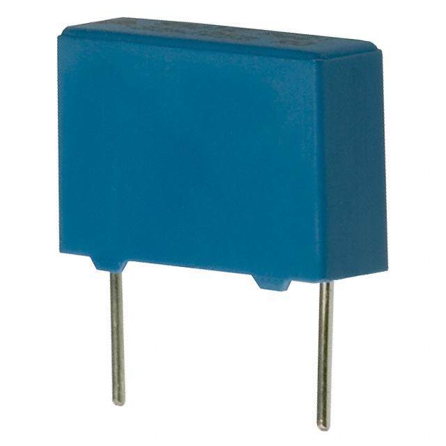
| 描述 | CAP TANT 330UF 75V 10%钽质电容器-湿式 330uF 75V 10% |
| ESR | 1 Ohms |
| ESR(等效串联电阻) | 1 欧姆 |
| 产品分类 | |
| 品牌 | Vishay / TansitorVishay Sprague |
| 产品手册 | |
| 产品图片 |
|
| rohs | 否无铅 / 符合限制有害物质指令(RoHS)规范要求 |
| 产品系列 | 钽电容器,钽质电容器-湿式,Vishay / Tansitor T16C337K075EZSST16 |
| 数据手册 | |
| 产品型号 | T16C337K075EZSST16C337K075EZSS |
| 不同温度时的使用寿命 | - |
| 产品 | Tantalum Wet High Reliability |
| 产品种类 | 钽质电容器-湿式 |
| 其它名称 | 1129-1009 |
| 制造商尺寸代码 | C |
| 制造商库存号 | C Case |
| 包装 | 散装 |
| 商标 | Vishay / Tansitor |
| 外壳直径 | 9.53 mm |
| 外壳长度 | 26.59 mm |
| 大小/尺寸 | 0.390" 直径 x 0.766" 长 (9.90mm x 19.46mm) |
| 安装类型 | 通孔 |
| 容差 | ±10%10 % |
| 封装 | Bulk |
| 封装/外壳 | 轴向 |
| 工作温度 | -55°C ~ 125°C |
| 工作温度范围 | - 55 C to + 85 C |
| 引线间距 | - |
| 标准包装 | 1 |
| 漏泄电流 | 3 uA |
| 特性 | 液态钽 |
| 电压-额定 | 75V |
| 电压额定值 | 75 V |
| 电压额定值DC | 75 V |
| 电容 | 330 uF330µF |
| 端接类型 | Axial |
| 类型 | 密封Wet Tantalum Extended Capacitance Glass-to-Tantalum Hermetic Seal |
| 系列 | T16 |
| 纹波电流 | 2100 mA |
| 高度-安装(最大值) | - |


- 商务部:美国ITC正式对集成电路等产品启动337调查
- 曝三星4nm工艺存在良率问题 高通将骁龙8 Gen1或转产台积电
- 太阳诱电将投资9.5亿元在常州建新厂生产MLCC 预计2023年完工
- 英特尔发布欧洲新工厂建设计划 深化IDM 2.0 战略
- 台积电先进制程称霸业界 有大客户加持明年业绩稳了
- 达到5530亿美元!SIA预计今年全球半导体销售额将创下新高
- 英特尔拟将自动驾驶子公司Mobileye上市 估值或超500亿美元
- 三星加码芯片和SET,合并消费电子和移动部门,撤换高东真等 CEO
- 三星电子宣布重大人事变动 还合并消费电子和移动部门
- 海关总署:前11个月进口集成电路产品价值2.52万亿元 增长14.8%


PDF Datasheet 数据手册内容提取
T16 www.vishay.com Vishay Wet Tantalum Capacitors, Extended Capacitance, Tantalum Case with Glass-to-Tantalum Hermetic Seal for -55 °C to +125 °C FEATURES • Enhanced performance, high reliability design • Terminations: axial, standard tin / lead (Sn / Pb) , 100 % tin (RoHS-compliant) available Available • Model T16 tantalum-case electrolytic capacitors provide all the advantages o f Available Vishay’s SuperTan® series devices, while offering improved reverse voltage and vibration capability • Increased thermal shock capability o f Available PERFORMANCE CHARACTERISTICS 300 cycles Refer to: Typical Performance Characteristics • Designed for the avionics and aerospace applications • Material categorization: for definitions of complianc e Operating Temperature: -55 °C to +85 °C please see www.vishay.com/doc?99912 (to +125 °C with voltage derating) Note Capacitance Tolerance: ± 10 %, ± 20 % standard * This datasheet provides information about parts that are DC Leakage Current (DCL Max.): at +25 °C and above: RoHS-compliant and / or parts that are non RoHS-compliant. For leakage current shall not exceed the values listed in th e example, parts with lead (Pb) terminations are not RoHS-compliant. Standard Ratings table. Please see the information / tables in this datasheet for details ORDERING INFORMATION T16 D 227 M 100 E Z S S MODEL CASE CAPACITANCE CAPACITANCE DC VOLTAGE RATING TERMINATION RELIABILITY / INSULATING ESR CODE TOLERANCE AT +85 °C AND PACKAGING SHOCK / SLEEVE VIBRATION LEVEL See This is expressed K = ± 10 % This is expressed in E = tin / lead, bulk, Z = standard S = sleeved S = Ratings in picofarads. M = ± 20 % volts. To complete standard H = high U = unsleeved standard and The first two the three-digit block, C = 100 % tin, bulk Case digits are the zeros precede the Codes significant voltage rating. Table. figures. The third is the number of zeros to follow. Note • Packaging: the use of formed plastic trays for packaging these axial lead components is standard. Tape and reel is not available due to th e unit weight DIMENSIONS in inches [millimeters] E L E D 1 0.0253 ± 0.002 [0.64 ± 0.05] dia. Weld (no. 22 AWG) tinned nickel leads solderable and weldable L Tantalum 2 CASE CODE L WEIGHT (g) D L 2 E TYPE T16 ST 1 (max.) (max.) 0.188 ± 0.016 0.453 + 0.031 / - 0.016 1.500 ± 0.250 A T1 0.734 [18.64] 2.6 [4.78 ± 0.41] [11.51 + 0.79 / - 0.41] [38.10 ± 6.35] 0.281 ± 0.016 0.641 + 0.031 / - 0.016 2.250 ± 0.250 B T2 0.922 [23.42] 6.2 [7.14 ± 0.41] [16.28 + 0.79 / - 0.41] [57.15 ± 6.35] 0.281 ± 0.016 1.008 + 0.031 / - 0.016 2.250 E L2 1.171 [29.75] 7.84 [7.14 ± 0.41] [25.60 + 0.79 / - 0.41] [57.15] 0.375 ± 0.016 0.766 + 0.031 / - 0.016 2.250 ± 0.250 C T3 1.047 [26.59] 11.6 [9.52 ± 0.41] [19.46 + 0.79 / - 0.41] [57.15 ± 6.35] 0.375 ± 0.016 1.062 + 0.031 / - 0.016 2.250 ± 0.250 D T4 1.343 [34.11] 17.7 [9.52 ± 0.41] [26.97 + 0.79 / - 0.41] [57.15 ± 6.35] Note • For insulated parts, add 0.015" [0.38 mm] to the diameter. The insulation shall lap over the ends of the capacitor body Revision: 21-Mar-2019 1 Document Number: 40139 For technical questions, contact: tantalum@vishay.com THIS DOCUMENT IS SUBJECT TO CHANGE WITHOUT NOTICE. THE PRODUCTS DESCRIBED HEREIN AND THIS DOCUMENT ARE SUBJECT TO SPECIFIC DISCLAIMERS, SET FORTH AT www.vishay.com/doc?91000
T16 www.vishay.com Vishay STANDARD RATINGS MAX. DCL MAX. CAPACITANCE AC CAPACITANCE MAX. ESR MAX. IMP. (μA) AT CHANGE (%) RIPPLE AT +25 °C CASE AT +25 °C AT -55 °C 120 Hz CODE PART NUMBER 120 Hz 120 Hz +85 °C +85 °C (μF) () () +25 °C AND -55 °C +85 °C +125 °C 40 kHz +125 °C (mARMS) 25 V AT 85 °C, 15 V AT 125 °C DC DC 120 A T16A127(1)025(2)(3)(4)(5) 1.30 25 1 5 -42 8 12 1250 560 B T16B567(1)025(2)(3)(4)(5) 0.83 12 2 10 -65 14 18 2000 1200 C T16C128(1)025(2)(3)(4)(5) 0.65 7 5 20 -70 15 20 2400 1800 D T16D188(1)025(2)(3)(4)(5) 0.50 7 6 25 -72 15 20 3000 30 V AT 85 °C, 20 V AT 125 °C DC DC 100 A T16A107(1)030(2)(3)(4)(5) 1.30 25 1 5 -38 8 12 1200 470 B T16B477(1)030(2)(3)(4)(5) 0.85 15 2 10 -65 14 18 1800 1000 C T16C108(1)030(2)(3)(4)(5) 0.70 7 7 25 -70 15 25 2200 1500 D T16D158(1)030(2)(3)(4)(5) 0.60 6 12 35 -72 15 25 2900 50 V AT 85 °C, 30 V AT 125 °C DC DC 68 A T16A686(1)050(2)(3)(4)(5) 1.50 35 1 5 -25 8 15 1050 220 B T16B227(1)050(2)(3)(4)(5) 0.90 17.5 2 10 -50 8 15 1800 470 C T16C477(1)050(2)(3)(4)(5) 0.75 10 3 25 -45 8 15 2100 680 D T16D687(1)050(2)(3)(4)(5) 0.70 8 5 40 -58 10 20 2700 60 V AT 85 °C, 40 V AT 125 °C DC DC 47 A T16A476(1)060(2)(3)(4)(5) 2.00 44 1 5 -25 8 12 1050 150 B T16B157(1)060(2)(3)(4)(5) 1.10 20 2 10 -40 8 15 1800 390 C T16C397(1)060(2)(3)(4)(5) 0.90 15 3 25 -45 8 15 2100 560 D T16D567(1)060(2)(3)(4)(5) 0.80 10 5 40 -58 8 15 2700 75 V AT 85 °C, 50 V AT 125 °C DC DC 33 A T16A336(1)075(2)(3)(4)(5) 2.50 66 1 5 -25 5 9 1050 110 B T16B117(1)075(2)(3)(4)(5) 1.30 24 2 10 -35 6 10 1650 220 E T16E227(1)075(2)(3)(4)(5) 0.80 12 5 30 -30 6 15 2500 250 E T16E257(1)075(2)(3)(4)(5) 0.80 12 5 30 -30 6 15 2500 330 C T16C337(1)075(2)(3)(4)(5) 1.00 12 3 30 -45 6 10 2100 470 D T16D477(1)075(2)(3)(4)(5) 0.90 12 5 50 -50 6 10 2700 100 V AT 85 °C, 65 V AT 125 °C DC DC 15 A T16A156(1)100(2)(3)(4)(5) 3.50 125 1 5 -18 3 10 1050 68 B T16B686(1)100(2)(3)(4)(5) 2.10 37 2 10 -30 4 12 1650 150 C T16C157(1)100(2)(3)(4)(5) 1.60 22 3 25 -35 6 12 2100 220 D T16D227(1)100(2)(3)(4)(5) 1.20 15 5 50 -40 6 12 2700 125 V AT 85 °C, 85 V AT 125 °C DC DC 10 A T16A106(1)125(2)(3)(4)(5) 5.50 175 1 5 -15 3 10 1050 47 B T16B476(1)125(2)(3)(4)(5) 2.30 47 2 10 -25 5 12 1650 82 C T16C826(1)125(2)(3)(4)(5) 1.80 40 3 25 -35 5 12 1950 100 C T16C107(1)125(2)(3)(4)(5) 1.80 35 3 25 -35 5 12 2100 150 D T16D157(1)125(2)(3)(4)(5) 1.60 20 5 50 -35 6 12 2700 Note • Part number definitions: (1) Capacitance tolerance: K, M (2) Termination / packaging: C = 100 % tin, bulk; E = standard, tin / lead, bulk (3) Reliability level: Z = standard (non-ER / 500 g / 50 g / 53.79 g); H = high (non-ER / 500 g / 80 g / 53.79 g) (4) Insulating sleeve: S = sleeved; U = unsleeved (5) ESR: S = standard Revision: 21-Mar-2019 2 Document Number: 40139 For technical questions, contact: tantalum@vishay.com THIS DOCUMENT IS SUBJECT TO CHANGE WITHOUT NOTICE. THE PRODUCTS DESCRIBED HEREIN AND THIS DOCUMENT ARE SUBJECT TO SPECIFIC DISCLAIMERS, SET FORTH AT www.vishay.com/doc?91000
T16 www.vishay.com Vishay TYPICAL PERFORMANCE CHARACTERISTICS OF T16 CAPACITORS ELECTRICAL CHARACTERISTICS ITEM PERFORMANCE CHARACTERISTICS Operating temperature range -55 °C to +85 °C (to +125 °C with voltage derating) Capacitor tolerance ± 20 %, ± 10 % at 120 Hz, at +25 °C Capacitor change by temperature Limit per Standard Ratings table ESR Limit per Standard Ratings table, at +25 °C, 120 Hz Impedance Limit per Standard Ratings table, at -55 °C, 120 Hz DCL (leakage current) Limit per Standard Ratings table AC ripple current Limit per Standard Ratings table, at +85 °C and 40 kHz Reverse voltage Reverse voltage shall be in accordance with MIL-PRF-39006, paragraphs 3.23 and 4.8.19. Surge voltage Surge voltage shall be in accordance with MIL-PRF-39006 and Table II of DLA 13017. The DC rated surge voltage is the maximum voltage to which the capacitors can be subjected under any conditions including transients and peak ripple at the highest line voltage. The DC surge voltage is 115 % of rated DC voltage. After the test, the capacitors shall meet the following requirements: a) DC leakage shall not exceed the specified value in catalog b) Capacitance shall be within +5 %, -20 % of initial value c) ESR shall not exceed the specified value in catalog PERFORMANCE CHARACTERISTICS ITEM PERFORMANCE CHARACTERISTICS Life testing Capacitors shall be capable of withstanding a 2000 h life test at a temperature +85 °C at rated voltage, or a 2000 h life test at 125 °C test at derated voltage. After the test, the capacitors shall meet the following requirements: a) DC leakage at 85 °C and 125 °C shall not exceed 125 % of the specified value b) DC leakage at 25 °C shall not exceed the specified value c) Capacitance shall be within +10 %, -20 % of initial value d) ESR shall not exceed 200 % of the specified value ENVIRONMENTAL CHARACTERISTICS ITEM CONDITION COMMENTS Seal MIL-PRF-39006 When the capacitors are tested as specified in MIL-PRF-39006, there shall be no evidence of leakage. Moisture resistance MIL-PRF-39006 Moisture resistance shall be in accordance with MIL-PRF-39006. Number of cycles: 10 continuous cycles Barometric pressure MIL-STD-202, method 105, condition E Altitude 150 000 feet (reduced) Revision: 21-Mar-2019 3 Document Number: 40139 For technical questions, contact: tantalum@vishay.com THIS DOCUMENT IS SUBJECT TO CHANGE WITHOUT NOTICE. THE PRODUCTS DESCRIBED HEREIN AND THIS DOCUMENT ARE SUBJECT TO SPECIFIC DISCLAIMERS, SET FORTH AT www.vishay.com/doc?91000
T16 www.vishay.com Vishay MECHANICAL CHARACTERISTICS ITEM CONDITION COMMENTS Shock (specified pulse) MIL-STD-202, method 213, The capacitors shall meet the requirements of MIL-PRF-39006. codes Z and H = test condition D (500 g) Vibration, high frequency MIL-STD-202, method 204, The capacitors shall meet the requirements of MIL-PRF-39006. code Z = test condition E (50 g peak) code H = test condition H (80 g peak) Random vibration MIL-STD-202, method 214, The capacitors shall meet the requirements of MIL-PRF-39006. test condition II-K (53.79 g RMS) Thermal shock MIL-STD-202, method 107, condition A Thermal shock shall be in accordance with MIL-PRF-39006 when tested for 300 cycles. Solderability MIL-STD-202, method 208, Solderability shall be in accordance with MIL-PRF-39006. ANSI/J-STD-002, test A Terminal strength MIL-STD-202, method 211 Terminal strength shall be in accordance with MIL-PRF-39006. Resistance to solder heat MIL-STD-202, method 210, condition C The capacitors shall meet the requirements of MIL-PRF-39006. Terminals MIL-STD-1276 Terminals shall be as specified in MIL-STD-1276. The length and diameter of the terminals shall be as specified in Dimensions table. All terminals shall be permanently secured internally and externally, as applicable. All external joints shall be welded. Marking MIL-STD-1285 Marking of capacitors conforms to method I of MIL-STD-1285 and include capacitance (in μF), capacitance tolerance letter, rated voltage, date code, lot symbol and Vishay trademark. SELECTOR GUIDES Tantalum Selector Guide www.vishay.com/doc?49054 Parameter Comparison Guide www.vishay.com/doc?42088 Revision: 21-Mar-2019 4 Document Number: 40139 For technical questions, contact: tantalum@vishay.com THIS DOCUMENT IS SUBJECT TO CHANGE WITHOUT NOTICE. THE PRODUCTS DESCRIBED HEREIN AND THIS DOCUMENT ARE SUBJECT TO SPECIFIC DISCLAIMERS, SET FORTH AT www.vishay.com/doc?91000
Legal Disclaimer Notice www.vishay.com Vishay Disclaimer ALL PRODUCT, PRODUCT SPECIFICATIONS AND DATA ARE SUBJECT TO CHANGE WITHOUT NOTICE TO IMPROV E RELIABILITY, FUNCTION OR DESIGN OR OTHERWISE. Vishay Intertechnology, Inc., its affiliates, agents, and employees, and all persons acting on its or their behalf (collectively, “Vishay”), disclaim any and all liability for any errors, inaccuracies or incompleteness contained in any datasheet or in any other disclosure relating to any product. Vishay makes no warranty, representation or guarantee regarding the suitability of the products for any particular purpose o r the continuing production of any product. To the maximum extent permitted by applicable law, Vishay disclaims (i) any and all liability arising out of the application or use of any product, (ii) any and all liability, including without limitation special, consequential or incidental damages, and (iii) any and all implied warranties, including warranties of fitness for particular purpose, non-infringement and merchantability. Statements regarding the suitability of products for certain types of applications are based on Vishay’s knowledge of typical requirements that are often placed on Vishay products in generic applications. Such statements are not binding statements about the suitability of products for a particular application. It is the customer’s responsibility to validate that a particular product with the properties described in the product specification is suitable for use in a particular application. Parameters provided in datasheets and / or specifications may vary in different applications and performance may vary over time. All operating parameters, including typical parameters, must be validated for each customer application by the customer’s technical experts. Product specifications do not expand or otherwise modify Vishay’s terms and conditions of purchase, including but not limited to the warranty expressed therein. Except as expressly indicated in writing, Vishay products are not designed for use in medical, life-saving, or life-sustainin g applications or for any other application in which the failure of the Vishay product could result in personal injury or death. Customers using or selling Vishay products not expressly indicated for use in such applications do so at their own risk . Please contact authorized Vishay personnel to obtain written terms and conditions regarding products designed for such applications. No license, express or implied, by estoppel or otherwise, to any intellectual property rights is granted by this documen t or by any conduct of Vishay. Product names and markings noted herein may be trademarks of their respective owners. © 2019 VISHAY INTERTECHNOLOGY, INC. ALL RIGHTS RESERVED Revision: 01-Jan-2019 1 Document Number: 91000
Mouser Electronics Authorized Distributor Click to View Pricing, Inventory, Delivery & Lifecycle Information: V ishay: T16D157K125EZSS T16D157M125EZSS T16D227K100EZSS T16D227M100EZSS T16D477K075EZSS T16D477M075EZSS T16D567K060EZSS T16D567M060EZSS T16D687K050EZSS T16D687M050EZSS T16B117K075EZSS T16B686K100EZSS T16C397K060EZSS T16C477K050EZSS T16B117M075EZSS T16B157K060EZSS T16B157M060EZSS T16B227K050EZSS T16B227M050EZSS T16B476K125EZSS T16B476M125EZSS T16B686M100EZSS T16C107K125EZSS T16C107M125EZSS T16C157K100EZSS T16C157M100EZSS T16C337K075EZSS T16C337M075EZSS T16C397M060EZSS T16C477M050EZSS T16D227K100CZSS T16A336K075CZSS