ICGOO在线商城 > 光电元件 > LED 照明 - 白色 > SZ5-P0-W0-00-U3V3-AA

 Datasheet下载
- 型号: SZ5-P0-W0-00-U3V3-AA
- 制造商: Seoul Semiconductor
- 库位|库存: xxxx|xxxx
- 要求:
| 数量阶梯 | 香港交货 | 国内含税 |
| +xxxx | $xxxx | ¥xxxx |
查看当月历史价格
查看今年历史价格
SZ5-P0-W0-00-U3V3-AA产品简介:
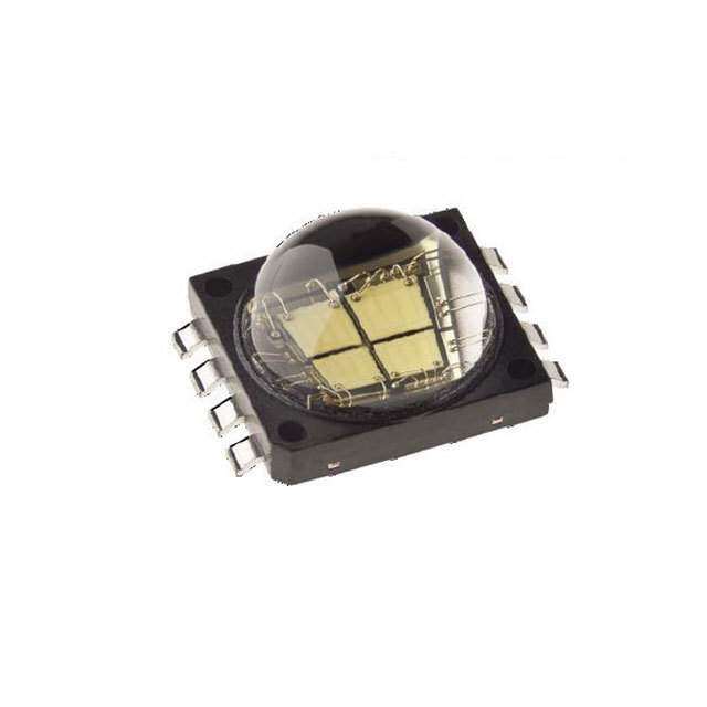
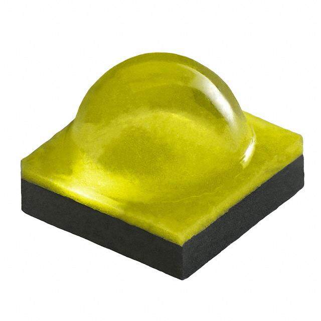
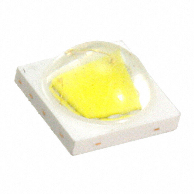
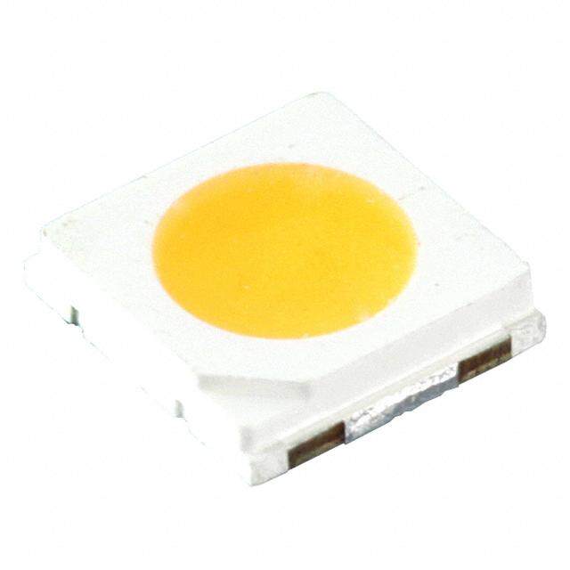
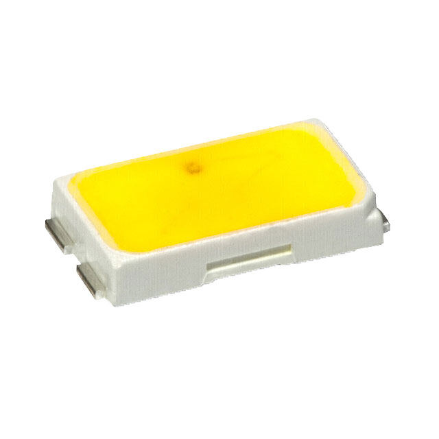
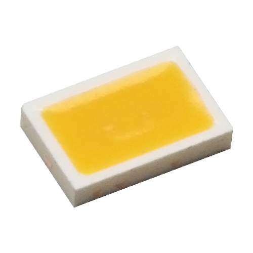
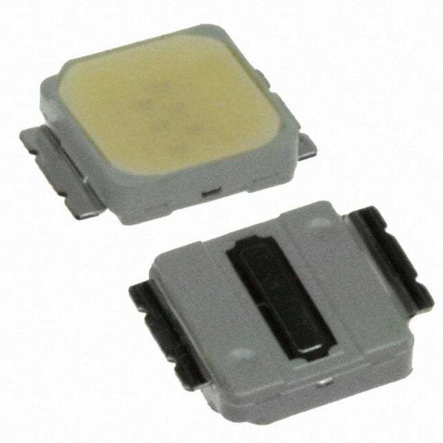
ICGOO电子元器件商城为您提供SZ5-P0-W0-00-U3V3-AA由Seoul Semiconductor设计生产,在icgoo商城现货销售,并且可以通过原厂、代理商等渠道进行代购。 SZ5-P0-W0-00-U3V3-AA价格参考。Seoul SemiconductorSZ5-P0-W0-00-U3V3-AA封装/规格:LED 照明 - 白色, LED Lighting SZ5-P White, Cool 6500K (6000K ~ 7000K) 3.2V 350mA 120° 1414 (3535 Metric)。您可以下载SZ5-P0-W0-00-U3V3-AA参考资料、Datasheet数据手册功能说明书,资料中有SZ5-P0-W0-00-U3V3-AA 详细功能的应用电路图电压和使用方法及教程。
| 参数 | 数值 |
| 25°C时通量,电流-测试 | 130 lm (109 lm ~ 150 lm) |
| 85°C时通量,电流-测试 | - |
| 产品目录 | |
| CCT(K) | 6500K (6000K ~ 7000K) |
| CRI(高显色指数) | 70 (标准) |
| 描述 | LED SMD COOL WHITE 6500K SMD |
| 产品分类 | |
| 品牌 | Seoul Semiconductor Inc |
| 数据手册 | |
| 产品图片 |
|
| 产品型号 | SZ5-P0-W0-00-U3V3-AA |
| rohs | 无铅 / 符合限制有害物质指令(RoHS)规范要求 |
| 产品系列 | SZ5-P |
| 不同测试电流时的流明/瓦 | 116 lm/W |
| 其它名称 | 897-1113-2 |
| 包装 | 带卷 (TR) |
| 安装类型 | 表面贴装 |
| 封装/外壳 | 2-SMD,无引线 |
| 封装热阻 | 5.5°C/W |
| 标准包装 | 1,000 |
| 电压-正向(Vf)(典型值) | 3.2V |
| 电流-最大值 | 1A |
| 电流-测试 | 350mA |
| 视角 | 120° |


PDF Datasheet 数据手册内容提取
AAPCPCWM_4828539:WP_0000001WP_0000001PCPCWM_4828539:WP_0000001WP_0000001 T eZZ -- cPP hoo nww i cee arr RoHS lLL DEE DD a tXX a 11 S00 h44 e99 Specification e00 t SSC-SZ5-P series AAuugguusstt 22001122 1 wwwwww..sseeoouullsseemmiiccoonn..ccoomm Document No. : SSC-QP-7-07-12
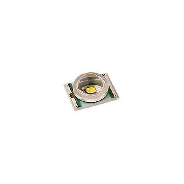
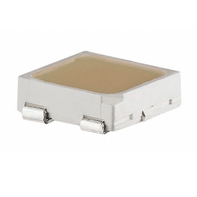
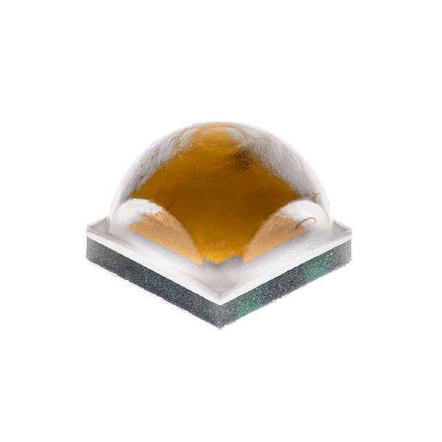
AAPCPCWM_4828539:WP_0000001WP_0000001PCPCWM_4828539:WP_0000001WP_0000001 TTT eeeZZZZZ ----- cccPPPPP hhhooooo nnnwwwww iii ccceeeee aaarrrrr l Dl Dl DLELELELELE SZ5-P series SZ5-P DDDDD aaa tttXXXXX aaa 11111 S S S00000 hhh44444 Description Features eee99999 • Super high Flux output eee00000 ttt The Z-Power series is designed for and high Luminance • Designed for high high current operation and high flux current operation output applications. • SMT solderable It incorporates state of the art SMD • Lead Free product • RoHS compliant design and low thermal resistant material. The Z Power LED is ideal light sources for general illumination applications, custom designed solutions, large backlights and Applications high performance torches. • General Torch • Architectural lighting • Projector light source • Traffic signals • Task lighting • Decorative / Pathway lighting • Remote / Solar powered lighting AAuugguusstt 22001122 2 wwwwww..sseeoouullsseemmiiccoonn..ccoomm Document No. : SSC-QP-7-07-12
AAPCPCWM_4828539:WP_0000001WP_0000001PCPCWM_4828539:WP_0000001WP_0000001 T eZZ -- cPP hoo nww i cee arr lLL Contents DEE DD a tXX a 11 S00 h44 e99 e00 t 1. Full code of SZ5-P series 2. Outline dimensions 3. Characteristics of SZ5-P0-W0-00 (pure) 4. Characteristic diagrams 5. CIE Chromaticity Diagram (pure) 6. Bin Code Description 77.. LLaabbeelliinngg 8. Packing 9. Recommended solder pad 10. Soldering 11. Precaution for use 12. Handling of Silicone Resin LEDs AAuugguusstt 22001122 3 wwwwww..sseeoouullsseemmiiccoonn..ccoomm Document No. : SSC-QP-7-07-12
AAPCPCWM_4828539:WP_0000001WP_0000001PCPCWM_4828539:WP_0000001WP_0000001 T eZZ -- cPP hoo nww i cee 1. Full code of SZ5-P series arr lLL DEE Full code form : X X X – X X – X X –X X DD 1 2 3 4 5 6 7 8 9 a tXX a 11 S00 1. Part Number h44 e99 e00 X Company t 1 X Z-Power LED series number 2 X PKG series 3 2. Internal Number X PCB Type 4 P P series X Revision number 5 X X Color Specification 6 7 W0 Pure white WN Neutral white WW Warm white X X Color Specification 8 9 C8 CRI min 80 85 CRI min 85 00 The others AAuugguusstt 22001122 4 wwwwww..sseeoouullsseemmiiccoonn..ccoomm Document No. : SSC-QP-7-07-12
AAPCPCWM_4828539:WP_0000001WP_0000001PCPCWM_4828539:WP_0000001WP_0000001 T eZZ -- cPP hoo nww i cee 2. Outline dimensions arr lLL DEE DD a tXX a 11 S00 h44 e99 e00 t Notes : [1] All dimensions are in millimeters. [2] Scale : none [3] Undefined tolerance is ±0.1mm AAuugguusstt 22001122 5 wwwwww..sseeoouullsseemmiiccoonn..ccoomm Document No. : SSC-QP-7-07-12
AAPCPCWM_4828539:WP_0000001WP_0000001PCPCWM_4828539:WP_0000001WP_0000001 T eZZ -- cPP hoo nww i cee 3. Characteristics of SZ5-P0-W0-00 (Pure) arr lLL DEE Pure White DD a tXX 1-1 Electro-Optical characteristics at 350mA (Ta=25℃, RH30%) a 11 S00 Value h44 Parameter Symbol Unit e99 Min Typ Max e00 t Ф [2] - 135 - V Luminous Flux [1] lm Ф (Tj=100℃) - 120 - V Correlated Color CCT - 6000 - K Temperature [3] CRI [6] R - 70 - - a Forward Voltage [4] V - 3.20 - V F Thermal resistance Rθ 5.5 K/W (J to S) J-S View Angle 2Θ ½ 120 deg. 11--22 AAbbssoolluuttee MMaaxxiimmuumm RRaattiinnggss Parameter Symbol Value Unit 1000 Forward Current I mA F 1800 (100ms, 1/10duty) Reverse Voltage V 5 V r Power Dissipation P 4.1 W d Junction Temperature T 145(@ I ≤ 1000mA) ºC j F Operating Temperature T -40 ~ +85 ºC opr Storage Temperature T -40 ~ +100 ºC stg ESD Sensitivity(HBM) [5] - 2 kV *Notes : [1] SSC maintains a tolerance of ±7% on flux and power measurements. [2] Ф is the total luminous flux output as measured with an integrating sphere. V [3] Correlated Color Temperature is derived from the CIE 1931 Chromaticity diagram. Color coordinate : ±0.005, CCT ±5% tolerance. [4] Tolerance is ±0.06V on forward voltage measurements [5] A zener diode is included to protect the product from ESD. [6] Tolerance is ±2.0 on CRI measurements AAuugguusstt 22001122 6 wwwwww..sseeoouullsseemmiiccoonn..ccoomm Document No. : SSC-QP-7-07-12
AAPCPCWM_4828539:WP_0000001WP_0000001PCPCWM_4828539:WP_0000001WP_0000001 T eZZ -- cPP hoo nww i cee 4. Characteristic diagrams arr lLL DEE DD a Color Spectrum tXX a 11 S00 (IF =350mA, Ta=25℃, RH30%) h44 e99 SZ5-M0-W0-00 e00 1.0 t 0.8 t u p ut 0.6 O e v i t a 0.4 el R 0.2 0.0 400 450 500 550 600 650 700 750 Wavelength[nm] AAuugguusstt 22001122 7 wwwwww..sseeoouullsseemmiiccoonn..ccoomm Document No. : SSC-QP-7-07-12
AAPCPCWM_4828539:WP_0000001WP_0000001PCPCWM_4828539:WP_0000001WP_0000001 T eZZ -- cPP hoo nww icee Forward Current Characteristics arr lLL DEDED Forward Current vs. Forward Voltage , Ta=25℃℃℃℃ a tXX a 11 SZ5-P0-W0-00 S00 1.0 h44 e99 e00 t ] 0.8 A [ t n e r ur 0.6 C d r a w 0.4 r o F 0.2 0.0 2.0 2.5 3.0 3.5 4.0 Forward Voltage[V] Forward Current vs. Normalized Relative Luminous Flux, Ta=25℃℃℃℃ 300 SZ5-P0-W0-00 250 ] % [ x u 200 Fl s u o n 150 mi u L e 100 v ti a el R 50 0 0.0 0.2 0.4 0.6 0.8 1.0 Forward Current [A] AAuugguusstt 22001122 8 wwwwww..sseeoouullsseemmiiccoonn..ccoomm Document No. : SSC-QP-7-07-12
AAPCPCWM_4828539:WP_0000001WP_0000001PCPCWM_4828539:WP_0000001WP_0000001 T eZZ -- cPP hoo nww icee Forward Current Characteristics arr lLL DEDED Forward Current vs. Chromaticity Coordinate, Ta=25℃℃℃℃ a tXX a11 0.015 S00 SZ5-P0-W0-00 h44 CIE X e99 0.010 CIE Y e00 hift t S e at 0.005 n di r o o 0.000 C y cit ati -0.005 m o r h C -0.010 -0.015 0.0 0.2 0.4 0.6 0.8 1.0 Forward Current [A] Forward Current vs. CCT, Ta=25℃℃℃℃ 200 SZ5-P0-W0-00 100 K] hift [ 0 S T C C -100 -200 0.0 0.2 0.4 0.6 0.8 1.0 Forward Current [A] AAuugguusstt 22001122 9 wwwwww..sseeoouullsseemmiiccoonn..ccoomm Document No. : SSC-QP-7-07-12
AAPCPCWM_4828539:WP_0000001WP_0000001PCPCWM_4828539:WP_0000001WP_0000001 T eZZ -- cPP hoo nww icee Junction Temperature Characteristics arr lLL DEE DD Junction Temperature vs. Relative Light Output at IF=350mA a tXX a 11 S00 SZ5-P0-W0-00 h44 100 e99 e00 ] % t t[ 80 u p t u O s 60 u o n mi u 40 L e v ti a el 20 R 0 20 40 60 80 100 120 140 JJuunnccttiioonn TTeemmppeerraattuurree[[ooCC]] Junction Temperature vs. Forward Voltage at IF=350mA 0.0 SZ5-P0-W0-00 V] -0.2 [ t f hi S e -0.4 g a t ol V d -0.6 r a w r o F -0.8 -1.0 20 40 60 80 100 120 140 Junction Temperature[oC] AAuugguusstt 22001122 10 wwwwww..sseeoouullsseemmiiccoonn..ccoomm Document No. : SSC-QP-7-07-12
AAPCPCWM_4828539:WP_0000001WP_0000001PCPCWM_4828539:WP_0000001WP_0000001 T eZZ -- cPP hoo nww icee Junction Temperature Characteristics arr lLL DEE DD Junction Temperature vs. Chromaticity Coordinate at IF=350mA a t X X a 11 S00 0.004 SZ5-P0-W0-00 h44 CIE X e99 CIE Y e00 0.002 t hift S e at 0.000 n di r o o -0.002 C y cit ati -0.004 m o r h C -0.006 -0.008 2200 4400 6600 8800 110000 112200 114400 Junction Temperature [oC] CCT vs. Junction Temperature at IF=350mA 400 SZ5-P0-W0-00 300 K] 200 hift [ S T C 100 C 0 -100 20 40 60 80 100 120 140 Junction Temperature [oC] AAuugguusstt 22001122 11 wwwwww..sseeoouullsseemmiiccoonn..ccoomm Document No. : SSC-QP-7-07-12
AAPCPCWM_4828539:WP_0000001WP_0000001PCPCWM_4828539:WP_0000001WP_0000001 T eZZ -- cPP hoo nww icee Characteristic diagrams arr lLL DEDED Ambient Temperature vs. Allowable Forward Current (Tjmax = 145℃℃℃℃, @1.0A) a t X X a 11 S00 h44 1000 e99 e00 t 800 ] A m [ t n e 600 r r u C m u 400 m xi Rj-a=10oC/W a M Rj-a=15oC/W 200 Rj-a=20 oC/W 0 0 20 40 60 80 100 120 140 Ambient Temperature [ooC] Radiation pattern at 350mA 0 1.0 30 0.8 x u Fl us 0.6 o n 60 mi u L e 0.4 v ati el R 0.2 0.0 90 -80 -60 -40 -20 0 Angle [deg] AAuugguusstt 22001122 12 wwwwww..sseeoouullsseemmiiccoonn..ccoomm Document No. : SSC-QP-7-07-12
AAPCPCWM_4828539:WP_0000001WP_0000001PCPCWM_4828539:WP_0000001WP_0000001 T eZZ -- cPP hoo nww i cee 5. CIE Chromaticity Diagram (Pure) arr lLL DEE [Ta = 25℃℃℃℃IF = 350mA] DD a tXX a 11 S00 h44 e99 e00 t AAuugguusstt 22001122 13 wwwwww..sseeoouullsseemmiiccoonn..ccoomm Document No. : SSC-QP-7-07-12
AAPCPCWM_4828539:WP_0000001WP_0000001PCPCWM_4828539:WP_0000001WP_0000001 T eZZ -- cPP hoo nww i cee 6. Bin Code Description arr lLL DEE DD a tXX a 11 S00 Bin Code h44 e99 Color Chromaticity Luminous Flux (lm) Forward Voltage (V) e00 Coordinate t @ IF = 350mA @ I = 350mA @ IF = 350mA F V2 B3 H Color Chromaticity Luminous Flux (lm) Forward Voltage(V) Coordinate @ IF = 350mA @ I = 350mA @ IF = 350mA F Bin Bin Bin Min. Max. Min. Max. Min. Max. Code Code Code UU33 110099 111188..55 GG 22..7755 33..0000 Ref. 13 pages V1 118.5 130 H 3.00 3.25 V2 130 140 I 3.25 3.50 V3 140 150 AAuugguusstt 22001122 14 wwwwww..sseeoouullsseemmiiccoonn..ccoomm Document No. : SSC-QP-7-07-12
AAPCPCWM_4828539:WP_0000001WP_0000001PCPCWM_4828539:WP_0000001WP_0000001 T eZZ -- cPP hoo nww i cee 7. Labeling arr lLL DEE DD X X X X a 10 11 12 13 tXX a 11 S00 1000 h44 e99 ############### e00 t SZ5-P0-W0-00 SZ5-P0-W0-00 Full code form X X X - X X - X X - X X 1 2 3 4 5 6 7 8 9 -X : Company 1 -X X : Z-Power LED series number 2 3 -X : PKG series 4 --XX :: RReevviissiioonn NNoo.. 55 -X X : Color 6 7 -X X : CRI Group 8 9 Rank X X X X 10 11 12 13 -X : Luminous Flux : LF [lm] 10 -X X : Color coordinates : x, y 11 12 -X : Forward Voltage : V [V] 13 F Lot No # # # # # # - # # # # - # # # 1 2 3 4 5 6 7 8 9 10 11 12 13 - # # : Year - # # # # : Mass order 1 2 7 8 9 10 - # # : Month - # # # : Tray No. 3 4 11 12 13 - # # : Day 5 6 AAuugguusstt 22001122 15 wwwwww..sseeoouullsseemmiiccoonn..ccoomm Document No. : SSC-QP-7-07-12
AAPCPCWM_4828539:WP_0000001WP_0000001PCPCWM_4828539:WP_0000001WP_0000001 T eZZ -- cPP hoo nww i cee 8. Packing arr lLL DEE DD Φ a CCCCAAAATTTTHHHHOOOODDDDEEEE MMMMAAAARRRRKKKK tXX a 11 S00 h44 e99 e00 t Φ 22 13 (1) Quantity : 1000pcs/Reel (2) Cumulative Tolerance : Cumulative Tolerance/10 pitches to be ±0.2mm (3) Adhesion Strength of Cover Tape : Adhesion strength to be 10-60g when the cover tape is turned off from the carrier tape at the angle of 10º to the carrier tape (4) Package : P/N, Manufacturing data Code No. and quantity to be indicated on a damp proof Package AAuugguusstt 22001122 16 wwwwww..sseeoouullsseemmiiccoonn..ccoomm Document No. : SSC-QP-7-07-12
AAPCPCWM_4828539:WP_0000001WP_0000001PCPCWM_4828539:WP_0000001WP_0000001 T eZZ -- cPP hoo nww i cee 8. Packing arr lLL DEE ●●●●Reel Packing Structure DD a Reel tXX a 11 X X X X S00 10 11 12 13 h44 1000 e99 e00 ############### t SZ5-P0-W0-00 SZ5-P0-W0-00 Aluminum Vinyl Bag X X X X 10 11 12 13 CAUTION LEVEL MOISTTUhRiEs bSaEgN cSoInTtIaViEns DEVICES 2 1000 ############################## SZ5-P0-W0-00 SZ5-P0-W0-00 Outer Box *Material: Paper(SW3B(B)) SIZE(mm) TYPE a b c 7inch 245 220 142 c Z LED TUV MADE IN KOREA Acriche PART : ******* CODE : ******* Semiconductor EcoLight Q'YT : ******* RoHS LOT NO : ******* b DATE :******* a AAuugguusstt 22001122 17 wwwwww..sseeoouullsseemmiiccoonn..ccoomm Document No. : SSC-QP-7-07-12
AAPCPCWM_4828539:WP_0000001WP_0000001PCPCWM_4828539:WP_0000001WP_0000001 T eZZ -- cPP hoo nww i cee 9. Recommended solder pad arr lLL DEE DD a tXX a 11 S00 h44 e99 e00 t Notes : [1] All dimensions are in millimeters. [2] Scale : none [3] This drawing without tolerances are for reference only [4] Undefined tolerance is ±0.1mm AAuugguusstt 22001122 18 wwwwww..sseeoouullsseemmiiccoonn..ccoomm Document No. : SSC-QP-7-07-12
AAPCPCWM_4828539:WP_0000001WP_0000001PCPCWM_4828539:WP_0000001WP_0000001 T eZZ -- cPP hoo nww i cee 10. Soldering arr lLL DEE DD a tXX a 11 S00 h44 e99 e00 t IPC/JEDEC J-STD-020 Profile Feature Sn-Pb Eutectic Assembly Pb-Free Assembly Average ramp-up rate (Tsmax to Tp) 3°C/second max. 3°C/second max. Preheat -Temperature Min (Tsmin) 100 °C 150 °C -Temperature Max (Tsmax) 150 °C 200 °C -Time (Tsmin to Tsmax) (ts) 60-120 seconds 60-180 seconds Time maintained above: -Temperature (TL) 183 °C 217 °C -Time (tL) 60-150 seconds 60-150 seconds Peak Temperature (Tp) 215℃ 260℃ Time within 5°C of actual Peak 10-30 seconds 20-40 seconds Temperature (tp)2 Ramp-down Rate 6 °C/second max. 6 °C/second max. Time 25°C to Peak Temperature 6 minutes max. 8 minutes max. * Caution 1. Reflow soldering is recommended not to be done more than two times. In the case of more than 24 hours passed soldering after first, LEDs will be damaged. 2. Repairs should not be done after the LEDs have been soldered. When repair is unavoidable, suitable tools must be used. 3. Die slug is to be soldered. 4. When soldering, do not put stress on the LEDs during heating. 5. After soldering, do not warp the circuit board. AAuugguusstt 22001122 19 wwwwww..sseeoouullsseemmiiccoonn..ccoomm Document No. : SSC-QP-7-07-12
AAPCPCWM_4828539:WP_0000001WP_0000001PCPCWM_4828539:WP_0000001WP_0000001 T eZZ -- cPP hoo nww i 11. Precaution for use cee arr lLL DEE (1) Storage DD a To avoid the moisture penetration, we recommend storing Z5P Series (Z Power) LEDs tXX a11 in a dry box with a desiccant . The recommended storage temperature range is 5℃ to 30℃ S00 and a maximum humidity of RH50%. h44 e99 (2) Use Precaution after Opening the Packaging e00 Use proper SMD techniques when the LED is to be soldered dipped as separation of the lens t may affect the light output efficiency. Pay attention to the following: a. Recommend conditions after opening the package - Sealing - Temperature : 5 ~ 40℃ Humidity : less than RH30% b. If the package has been opened more than 1 year (MSL 2) or the color of the desiccant changes, components should be dried for 10-12hr at 60±5℃ (3) Do not apply mechanical force or excess vibration during the cooling process to normal temperature after soldering. (4) Do not rapidly cool device after soldering. (5) Components should not be mounted on warped (non coplanar) portion of PCB. ((66)) RRaaddiiooaaccttiivvee eexxppoossuurree iiss nnoott ccoonnssiiddeerreedd ffoorr tthhee pprroodduuccttss lliisstteedd hheerree iinn.. (7) Gallium arsenide is used in some of the products listed in this publication. These products are dangerous if they are burned or shredded in the process of disposal. It is also dangerous to drink the liquid or inhale the gas generated by such products when chemically disposed of. (8) This device should not be used in any type of fluid such as water, oil, organic solvent and etc. When washing is required, IPA (Isopropyl Alcohol) should be used. (9) When the LEDs are in operation the maximum current should be decided after measuring the package temperature. (10) LEDs must be stored properly to maintain the device. If the LEDs are stored for 3 months or more after being shipped from SSC, a sealed container with a nitrogen atmosphere should be used for storage. (11) The appearance and specifications of the product may be modified for improvement without notice. (12) Long time exposure of sunlight or occasional UV exposure will cause lens discoloration. AAuugguusstt 22001122 20 wwwwww..sseeoouullsseemmiiccoonn..ccoomm Document No. : SSC-QP-7-07-12
AAPCPCWM_4828539:WP_0000001WP_0000001PCPCWM_4828539:WP_0000001WP_0000001 T eZZ -- cPP hoo nww i 11. Precaution for use cee arr lLL DEE (13) VOCs (Volatile organic compounds) emitted from materials used in the construction of DD a t X X fixtures can penetrate silicone encapsulants of LEDs and discolor when exposed to heat and a 11 S00 photonic energy. The result can be a significant loss of light output from the fixture. h44 Knowledge of the properties of the materials selected to be used in the construction of e99 e00 fixtures can help prevent these issues. t (14) The slug is isolated from anode electrically. Therefore, we recommend that you don’t isolate the heat sink. (15) Attaching LEDs, do not use adhesives that outgas organic vapor. (16) The driving circuit must be designed to allow forward voltage only when it is ON or OFF. If the reverse voltage is applied to LED, migration can be generated resulting in LED damage. AAuugguusstt 22001122 21 wwwwww..sseeoouullsseemmiiccoonn..ccoomm Document No. : SSC-QP-7-07-12
AAPCPCWM_4828539:WP_0000001WP_0000001PCPCWM_4828539:WP_0000001WP_0000001 T eZZ -- cPP hoo nww i 12. Handling of Silicone Resin LEDs cee arr lLL DEE (1) During processing, mechanical stress on the surface should be minimized as much DD a as possible. Sharp objects of all types should not be used to pierce the sealing tXX a compound. 11 S00 h44 e99 e00 t (2) In general, LEDs should only be handled from the side. By the way, this also applies to LEDs without a silicone sealant, since the surface can also become scratched. (3) When populating boards in SMT production, there are basically no restrictions regarding the form of the pick and place nozzle, except that mechanical pressure on the surface of the resin must be prevented. This is assured by choosing a pick and place nozzle which is larger than the LED’s rreefflleeccttoorr aarreeaa.. (4) Silicone differs from materials conventionally used for the manufacturing of LEDs. These conditions must be considered during the handling of such devices. Compared to standard encapsulants, silicone is generally softer, and the surface is more likely to attract dust. As mentioned previously, the increased sensitivity to dust requires special care during processing. In cases where a minimal level of dirt and dust particles cannot be guaranteed, a suitable cleaning solution must be applied to the surface after the soldering of components. (5) SSC suggests using isopropyl alcohol for cleaning. In case other solvents are used, it must be assured that these solvents do not dissolve the package or resin. Ultrasonic cleaning is not recommended. Ultrasonic cleaning may cause damage to the LED. (6) Please do not mold this product into another resin (epoxy, urethane, etc) and do not handle this product with acid or sulfur material in sealed space. (7) Avoid leaving fingerprints on silicone resin parts. AAuugguusstt 22001122 22 wwwwww..sseeoouullsseemmiiccoonn..ccoomm Document No. : SSC-QP-7-07-12