ICGOO在线商城 > 分立半导体产品 > 二极管 - 整流器 - 单 > STTH802FP
 Datasheet下载
- 型号: STTH802FP
- 制造商: STMicroelectronics
- 库位|库存: xxxx|xxxx
- 要求:
| 数量阶梯 | 香港交货 | 国内含税 |
| +xxxx | $xxxx | ¥xxxx |
查看当月历史价格
查看今年历史价格
STTH802FP产品简介:
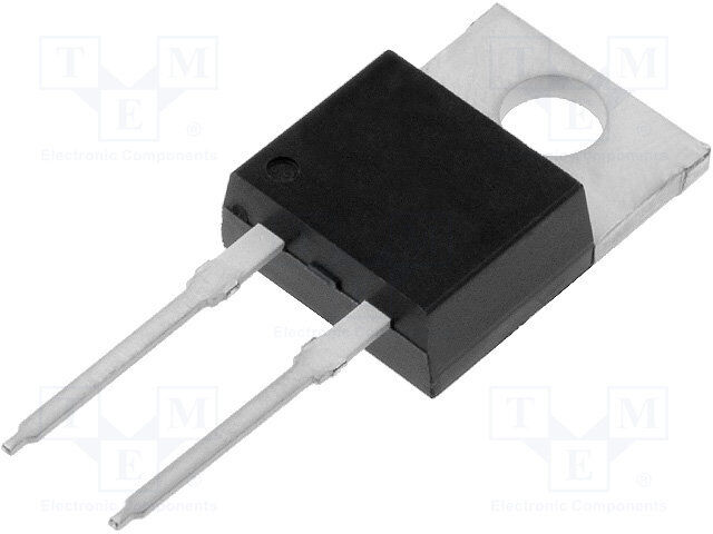
ICGOO电子元器件商城为您提供STTH802FP由STMicroelectronics设计生产,在icgoo商城现货销售,并且可以通过原厂、代理商等渠道进行代购。 STTH802FP价格参考。STMicroelectronicsSTTH802FP封装/规格:二极管 - 整流器 - 单, 标准 通孔 二极管 200V 8A TO-220FPAC。您可以下载STTH802FP参考资料、Datasheet数据手册功能说明书,资料中有STTH802FP 详细功能的应用电路图电压和使用方法及教程。
| 参数 | 数值 |
| 产品目录 | |
| 描述 | DIODE ULTRA FAST 200V 8A TO220FP整流器 Recovery Diode Ultra Fast |
| 产品分类 | 单二极管/整流器分离式半导体 |
| 品牌 | STMicroelectronics |
| 产品手册 | |
| 产品图片 |
|
| rohs | 符合RoHS无铅 / 符合限制有害物质指令(RoHS)规范要求 |
| 产品系列 | 二极管与整流器,整流器,STMicroelectronics STTH802FP- |
| 数据手册 | |
| 产品型号 | STTH802FP |
| 不同If时的电压-正向(Vf) | 1.05V @ 8A |
| 不同 Vr、F时的电容 | - |
| 不同 Vr时的电流-反向漏电流 | 6µA @ 200V |
| 二极管类型 | 标准 |
| 产品 | Ultra Fast Recovery Rectifiers |
| 产品目录页面 | |
| 产品种类 | 整流器 |
| 供应商器件封装 | TO-220FPAC |
| 其它名称 | 497-5285-5 |
| 其它有关文件 | http://www.st.com/web/catalog/sense_power/FM64/CL830/SC4/SS1650/PF134644?referrer=70071840 |
| 包装 | 管件 |
| 反向恢复时间(trr) | 30ns |
| 反向电压 | 200 V |
| 反向电流IR | 6 uA |
| 商标 | STMicroelectronics |
| 安装类型 | 通孔 |
| 安装风格 | Through Hole |
| 封装 | Tube |
| 封装/外壳 | TO-220-2 全封装,隔离接片 |
| 封装/箱体 | TO-220-2 FP |
| 工作温度-结 | 175°C (最大) |
| 工厂包装数量 | 50 |
| 恢复时间 | 30 ns |
| 最大工作温度 | + 175 C |
| 最大浪涌电流 | 100 A |
| 最小工作温度 | - 65 C |
| 标准包装 | 50 |
| 正向电压下降 | 1.05 V |
| 正向连续电流 | 8 A |
| 热阻 | 5.5°C/W Jc |
| 电压-DC反向(Vr)(最大值) | 200V |
| 电流-平均整流(Io) | 8A |
| 系列 | STTH802 |
| 速度 | 快速恢复 =< 500 ns,> 200mA(Io) |
| 配置 | Single |


PDF Datasheet 数据手册内容提取
STTH802 Ultrafast recovery diode Datasheet - production data Description A K This device uses ST's 200 V planar Pt doping K K K technology, and is especially suited for switching mode base drive and transistor circuits. Packaged in TO-220AC, TO-220FPAC, DPAK, and D2PAK this device is intended for use in low A A A voltage, high frequency inverters, freewheeling TO-220AC K NC NC and polarity protection. D2PAK Table 1: Device summary Symbol Value K K IF(AV) 8 A NC VRRM 200 V NC A A Tj (max.) 175 °C A K DPAK VF (typ.) 0.8 V TO-220FPAC trr (typ.) 17 ns Features Very low conduction losses Negligible switching losses Low forward and reverse recovery time High junction temperature ECOPACK®2 compliant component for DPAK and D²PAK on demand Insulated package: TO-220FPAC Insulating voltage: 2000 V sine RMS August 2017 DocID12362 Rev 3 1/17 This is information on a product in full production. www.st.com
Characteristics STTH802 1 Characteristics Table 2: Absolute ratings (limiting values at 25 °C, unless otherwise specified) Symbol Parameter Value Unit VRRM Repetitive peak reverse voltage 200 V IF(RMS) Forward rms current 16 A TO-220AC, DPAK, Average forward current D2PAK TC = 145 °C IF(AV) δ = 0.5, square wave 8 A TO-220FPAC TC = 125 °C Surge non repetitive IFSM forward current tp = 10 ms sinusoidal 100 A Tstg Storage temperature range -65 to +175 °C Tj Maximum operating junction temperature 175 °C Table 3: Thermal parameter Symbol Parameter Max. value Unit TO-220AC, DPAK, D2PAK 3.2 Rth(j-c) Junction to case °C/W TO-220FPAC 5.5 Table 4: Static electrical characteristics Symbol Parameter Test conditions Min. Typ. Max. Unit Tj = 25 °C - 6 IR(1) Reverse leakage current VR = VRRM µA Tj = 125 °C - 6 60 Tj = 25 °C - 0.95 1.05 VF(2) Forward voltage drop IF = 8 A V Tj = 150 °C - 0.80 0.90 Notes: (1)Pulse test: tp = 5 ms, δ < 2% (2)Pulse test: tp = 380 µs, δ < 2% To evaluate the conduction losses, use the following equation: P = 0.73 x I + 0.021 x I 2 F(AV) F (RMS) 2/17 DocID12362 Rev 3
STTH802 Characteristics Table 5: Dynamic electrical characteristics Symbol Parameter Test conditions Min. Typ. Max. Unit IF = 1 A, Tj = 25 °C dIF/dt = -50 A/µs, - 25 30 ns VR = 30 V trr Reverse recovery time IF = 1 A, Tj = 25 °C dIF/dt = -100 A/µs, - 17 22 ns VR = 30 V Reverse recovery IF = 8 A, IRM current Tj = 125 °C dIF/dt = -200 A/µs, - 5.5 7.0 A VR = 160 V IF = 8 A, tfr Forward recovery time Tj = 25 °C dIF/dt = 50 A/µs, - 150 ns VFR = 1.1 x VFmax VFP Fvoolrtwagaerd recovery Tj = 25 °C IdFI F=/d 8t =A ,5 0 A/µs - 1.5 V DocID12362 Rev 3 3/17
Characteristics STTH802 1.1 Characteristics (curves) Figure 2: Forward voltage drop versus forward Figure 1: Peak current versus duty cycle current (typical values) IM(A) 100 TT IIMM 80 dδ==ttpp//TT ttpp 60 PP ==55WW 40 PP ==22WW PP ==11WW 20 δ 0 0.0 0.1 0.2 0.3 0.4 0.5 0.6 0.7 0.8 0.9 1.0 Figure 3: Forward voltage drop versus forward Figure 4: Relative variation of thermal impedance, current (maximum values) junction to case, versus pulse duration Z /R th(j-c) th(j-c) 1.0 Single pulse TO-220AC DPAK D2PAK tp(s) 0.1 1.E-03 1.E-02 1.E-01 1.E+00 Figure 5: Relative variation of thermal impedance, Figure 6: Junction capacitance versus reverse junction to case, versus pulse duration applied voltage (typical values) Z /R C(pF) th(j-c) th(j-c) 1.0 100 Single pulse F=1MHz TO-220FPAC Vosc=30mVRMS Tj=25°C 0.1 tp(s) VR(V) 0.0 10 1.E-03 1.E-02 1.E-01 1.E+00 1.E+01 1 10 100 1000 4/17 DocID12362 Rev 3
STTH802 Characteristics Figure 7: Reverse recovery charges versus dIF/dt Figure 8: Reverse recovery time versus dIF/dt (typical values) (typical values) Q (nC) t (ns) rr rr 160 80 140 VRIF==1860AV 70 VRIF==1860AV 120 60 100 50 Tj=125°C 80 40 Tj=125°C 60 30 Tj=25°C 40 20 Tj=25°C 20 10 dIF/dt(A/µs) dIF/dt(A/µs) 0 0 10 100 1000 10 100 1000 Figure 9: Peak reverse recovery current versus Figure 10: Relative variation of dynamic dIF/dt (typical values) parameters versus junction temperature I (A) 1.4 RM 12 I=8A 10 VRIF==1860AV 1.2 RefereVnRcF=e:1T6j0=V125°C 1.0 8 I 0.8 RM 6 Tj=125°C 0.6 Q rr 4 0.4 2 0.2 Tj=25°C dIF/dt(A/µs) Tj(°C) 0 0.0 10 100 1000 25 50 75 100 125 150 Figure 11: Thermal resistance, junction to ambient, Figure 12: Thermal resistance, junction to ambient, versus copper surface under tab versus copper surface under tab 80 Rth(j-a)(°C/W) 100Rth(j-a)(°C/W) D²PAK DPAK 70 EpoxyprintedboardFR4,copperthickness=35µm 90 80 60 70 50 60 40 50 30 40 30 20 20 Epoxy printed board FR4, eCu= 35 µm 10 SCu(cm²) 10 SCu(cm²) 0 0 0 5 10 15 20 25 30 35 40 0 5 10 15 20 25 30 35 40 DocID12362 Rev 3 5/17
Package information STTH802 2 Package information In order to meet environmental requirements, ST offers these devices in different grades of ECOPACK® packages, depending on their level of environmental compliance. ECOPACK® specifications, grade definitions and product status are available at: www.st.com. ECOPACK® is an ST trademark. Cooling method: by conduction (C) Epoxy meets UL 94,V0 Recommended torque value: 0.55 N·m (for TO-220AC and TO-220FPAC) Maximum torque value: 0.7 N·m (for TO-220AC and TO-220FPAC) 6/17 DocID12362 Rev 3
STTH802 Package information 2.1 D²PAK package information Figure 13: D²PAK package outline This package drawing may slightly differ from the physical package. However, all the specified dimensions are guaranteed. DocID12362 Rev 3 7/17
Package information STTH802 Table 6: D²PAK package mechanical data Dimensions Ref. Millimeters Inches Min. Max. Min. Max. A 4.36 4.60 0.172 0.181 A1 0.00 0.25 0.000 0.010 b 0.70 0.93 0.028 0.037 b2 1.14 1.70 0.045 0.067 c 0.38 0.69 0.015 0.027 c2 1.19 1.36 0.047 0.053 D 8.60 9.35 0.339 0.368 D1 6.90 8.00 0.272 0.311 D2 1.10 1.50 0.043 0.060 E 10.00 10.55 0.394 0.415 E1 8.10 8.90 0.319 0.346 E2 6.85 7.25 0.266 0.282 e 2.54 typ. 0.100 e1 4.88 5.28 0.190 0.205 H 15.00 15.85 0.591 0.624 J1 2.49 2.90 0.097 0.112 L 1.90 2.79 0.075 0.110 L1 1.27 1.65 0.049 0.065 L2 1.30 1.78 0.050 0.070 R 0.4 typ. 0.015 V2 0° 8° 0° 8° 8/17 DocID12362 Rev 3
STTH802 Package information Figure 14: D²PAK recommended footprint (dimensions in mm) DocID12362 Rev 3 9/17
Package information STTH802 2.2 DPAK package information Figure 15: DPAK package outline This package drawing may slightly differ from the physical package. However, all the specified dimensions are guaranteed. 10/17 DocID12362 Rev 3
STTH802 Package information Table 7: DPAK package mechanical data Dimensions Ref. Millimeters Inches Min. Max. Min. Max. A 2.18 2.40 0.085 0.094 A1 0.90 1.10 0.035 0.043 A2 0.03 0.23 0.001 0.009 b 0.64 0.90 0.025 0.035 b4 4.95 5.46 0.194 0.215 c 0.46 0.61 0.018 0.024 c2 0.46 0.60 0.018 0.023 D 5.97 6.22 0.235 0.244 D1 4.95 5.60 0.194 0.220 E 6.35 6.73 0.250 0.265 E1 4.32 5.50 0.170 0.216 e 2.286 typ. 0.090 typ. e1 4.40 4.70 0.173 0.185 H 9.35 10.40 0.368 0.409 L 1.0 1.78 0.039 0.070 L2 1.27 0.050 L4 0.60 1.02 0.023 0.040 V2 -8° +8° -8° +8° Figure 16: DPAK recommended footprint (dimensions in mm) DocID12362 Rev 3 11/17
Package information STTH802 2.3 TO-220AC package information Figure 17: TO-220AC package outline 12/17 DocID12362 Rev 3
STTH802 Package information Table 8: TO-220AC package mechanical data Dimensions Ref. Millimeters Inches Min. Max. Min. Max. A 4.40 4.60 0.173 0.181 C 1.23 1.32 0.048 0.051 D 2.40 2.72 0.094 0.107 E 0.49 0.70 0.019 0.027 F 0.61 0.88 0.024 0.034 F1 1.14 1.70 0.044 0.066 G 4.95 5.15 0.194 0.202 H2 10.00 10.40 0.393 0.409 L2 16.40 typ. 0.645 typ. L4 13.00 14.00 0.511 0.551 L5 2.65 2.95 0.104 0.116 L6 15.25 15.75 0.600 0.620 L7 6.20 6.60 0.244 0.259 L9 3.50 3.93 0.137 0.154 M 2.6 typ. 0.102 typ. ØI 3.75 3.85 0.147 0.151 DocID12362 Rev 3 13/17
Package information STTH802 2.4 TO-220FPAC package information Figure 18: TO-220FPAC package outline A H B Dia L6 L2 L7 L3 D F1 L4 F E G1 G 14/17 DocID12362 Rev 3
STTH802 Package information Table 9: TO-220FPAC package mechanical data Dimensions Ref. Millimeters Inches Min. Max. Min. Max. A 4.40 4.60 0.173 0.181 B 2.50 2.70 0.098 0.106 D 2.50 2.75 0.098 0.108 E 0.45 0.70 0.018 0.027 F 0.75 1.00 0.030 0.039 F1 1.15 1.70 0.045 0.067 G 4.95 5.20 0.195 0.205 G1 2.40 2.70 0.094 0.106 H 10.00 10.40 0.393 0.409 L2 16.00 typ. 0.630 typ. L3 28.60 30.60 0.126 1.205 L4 9.80 10.60 0.386 0.417 L6 15.90 16.40 0.626 0.646 L7 9.00 9.30 0.354 0.366 Dia. 3.00 3.20 0.118 0.126 DocID12362 Rev 3 15/17
Ordering information STTH802 3 Ordering information Table 10: Ordering information Order code Marking Package Weight Base qty Delivery mode STTH802D STTH802 TO-220AC 1.86g 50 Tube STTH802FP STTH802 TO-220FPAC 1.9g 50 Tube STTH802B-TR STTH 802 DPAK 0.32g 2500 Tape and reel STTH802G STTH802 D2PAK 1.38g 50 Tube STTH802G-TR STTH802 D2PAK 1.38g 1000 Tape and reel 4 Revision history Table 11: Document revision history Date Revision Changes 03-may-2006 1 First issue. 22-Sep-2006 2 Added D2PAK package. Updated features and image in cover page. Updated Section 1.1: "Characteristics (curves)". 07-Aug-2017 3 Updated Section 2: "Package information". Minor text changes. 16/17 DocID12362 Rev 3
STTH802 IMPORTANT NOTICE – PLEASE READ CAREFULLY STMicroelectronics NV and its subsidiaries (“ST”) reserve the right to make changes, corrections, enhancements, modifications, and improvements to ST products and/or to this document at any time without notice. Purchasers should obtain the latest relevant information on ST products before placing orders. ST products are sold pursuant to ST’s terms and conditions of sale in place at the time of order acknowledgement. Purchasers are solely responsible for the choice, selection, and use of ST products and ST assumes no liability for application assistance or the design of Purchasers’ products. No license, express or implied, to any intellectual property right is granted by ST herein. Resale of ST products with provisions different from the information set forth herein shall void any warranty granted by ST for such product. ST and the ST logo are trademarks of ST. All other product or service names are the property of their respective owners. Information in this document supersedes and replaces information previously supplied in any prior versions of this document. © 2017 STMicroelectronics – All rights reserved DocID12362 Rev 3 17/17
Mouser Electronics Authorized Distributor Click to View Pricing, Inventory, Delivery & Lifecycle Information: S TMicroelectronics: STTH802B-TR STTH802D STTH802FP STTH802G-TR STTH802G STTH802B