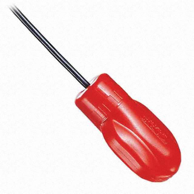
ICGOO在线商城 > STA7132MPR
- 型号: STA7132MPR
- 制造商: Sanken
- 库位|库存: xxxx|xxxx
- 要求:
| 数量阶梯 | 香港交货 | 国内含税 |
| +xxxx | $xxxx | ¥xxxx |
查看当月历史价格
查看今年历史价格
STA7132MPR产品简介:
ICGOO电子元器件商城为您提供STA7132MPR由Sanken设计生产,在icgoo商城现货销售,并且可以通过原厂、代理商等渠道进行代购。 提供STA7132MPR价格参考以及SankenSTA7132MPR封装/规格参数等产品信息。 你可以下载STA7132MPR参考资料、Datasheet数据手册功能说明书, 资料中有STA7132MPR详细功能的应用电路图电压和使用方法及教程。
| 参数 | 数值 |
| 产品目录 | 集成电路 (IC) |
| 描述 | IC MOTOR DRIVER PAR 18ZIP |
| 产品分类 | PMIC - 电机, 电桥式驱动器 |
| 品牌 | Sanken |
| 数据手册 | |
| 产品图片 | |
| 产品型号 | STA7132MPR |
| rohs | 无铅 / 符合限制有害物质指令(RoHS)规范要求 |
| 产品系列 | - |
| 供应商器件封装 | 18-ZIP |
| 功能 | 功率桥 - 逻辑驱动功率级 |
| 包装 | 散装 |
| 安装类型 | 通孔 |
| 封装/外壳 | 18-SIP(弯曲和交错引线) |
| 工作温度 | -20°C ~ 80°C |
| 应用 | 通用 |
| 接口 | 并联 |
| 标准包装 | 3,300 |
| 特色产品 | http://www.digikey.cn/product-highlights/zh/sta7130mpr-series-unipolar-driver-ics/52298 |
| 电压-电源 | 10 V ~ 44 V |
| 电压-负载 | 10 V ~ 44 V |
| 电机类型-AC,DC | 有刷直流 |
| 电机类型-步进 | 单极 |
| 电流-输出 | 1A |
| 输出配置 | 半桥, (2) 双路 |





- 商务部:美国ITC正式对集成电路等产品启动337调查
- 曝三星4nm工艺存在良率问题 高通将骁龙8 Gen1或转产台积电
- 太阳诱电将投资9.5亿元在常州建新厂生产MLCC 预计2023年完工
- 英特尔发布欧洲新工厂建设计划 深化IDM 2.0 战略
- 台积电先进制程称霸业界 有大客户加持明年业绩稳了
- 达到5530亿美元!SIA预计今年全球半导体销售额将创下新高
- 英特尔拟将自动驾驶子公司Mobileye上市 估值或超500亿美元
- 三星加码芯片和SET,合并消费电子和移动部门,撤换高东真等 CEO
- 三星电子宣布重大人事变动 还合并消费电子和移动部门
- 海关总署:前11个月进口集成电路产品价值2.52万亿元 增长14.8%
.jpg)
PDF Datasheet 数据手册内容提取
1-2-1 2-Phase Stepper Motor Unipolar Driver ICs STA7130MPR/7131MPR/7132MPR 2-Phase to 2W 1-2 Phase Excitation Support, Built-in Sequencer ■ Features ■ Absolute Maximum Ratings (Ta=25°C) •Lineup of built-in current sense resistor and Parameter Symbol Ratings Unit Remarks built-in protection circuit-type Motor Supply Voltage VM 46 V •P44o wVe nr osrumpapll yo pvoelrtaatginegs ,r aVnBgBe: 46 V (max), 10 to Driver Supply Voltage VBB 46 V Output Current Io *1 A Mode F •Maximum output currents: 1 A, 1.5 A, and 2 A Logic Input Voltage VIN –0.3 to +6 V •Supporting the clock-input-method micro-step REF Input Voltage VREF –0.3 to +6 V drive (built-in sequencer) Sense Voltage VRS ±0.5 V Excluding tw<1µs •Sofef ltfi-mexecitation PWM current control with fixed Power Dissipation PD 132..55 W WWhheenn TTac == 2255°°CC •Synchronous PWM chopping function Junction Temperature Tj +150 °C prevents motor noise in Hold mode Operating Ambient Temperature Ta –20 to +80 °C •Sleep mode for reducing the IC input current Storage Temperature Tstg –30 to +150 °C in stand-by state *1: Output current value may be limited for the STA7130MPR (1.0 A), 7131MPR (1.5 A), and 7132MPR (2.0 A), •ZIP type 18-pin molded package (STA depending on the duty ratio, ambient temperature, and heating conditions. package) Do not exceed junction temperature of Tj under any circumstances. ■ Recommended Operating Conditions Rating Parameter Symbol Unit Remarks min. max. Motor Supply Voltage VM 44 V Driver Supply Voltage VBB 10 44 V Case Temperature TC 85 °C Temperature at Pin-10 Lead (without Fin) ■ Electrical Characteristics (VDD=5V, VBB=24V, Ta=25°C, unless otherwise specified) Ratings Parameter Symbol Unit Conditions min. typ. max. Main Supply Current IBB 10 mA In operation IBBS 3 mA Sleep 1 and Sleep 2 modes Output MOSFET Breakdown Voltage V(BR)DSS 100 V 0.7 0.85 STA7130MPR Output MOSFET ON Resistance RDS(ON) 0.25 0.4 Ω STA7131MPR 0.18 0.24 STA7132MPR 0.85 1.1 STA7130MPR Output MOSFET Diode Forward Voltage VF 0.95 1.2 V STA7131MPR 0.95 2.1 STA7132MPR Maximum Clock Frequency Fclock 250 kHz When Clock Duty = 50% Logic Input Voltage VIL 0.7 V VIH 2.3 Logic Input Current IIL ±10 µA IIH ±10 REF Input Voltage VREF 0 0.9 V VREFS 2.0 5.5 Output OFF (Sleep 1) REF Input Current IREF ±10 µA Sense Voltage VSENSE VREF/3-0.03 VREF/3 VREF/3+0.03 V When step reference current ratio is 100% Sleep-Enable Recovery Time TSE 100 µS Sleep1&Sleep2 Switching Time tcon 1.4 µS Clock → Out ON tcoff 0.7 µS Clock → Out OFF 0.305 STA7130MPR Sense Resistance RS 0.205 Ω STA7131MPR 0.155 STA7132MPR Overcurrent Sense Voltage Vocp 0.65 0.7 0.75 V When motor coil shorts out 2.3 STA7130MPR OVovceprc÷uRrsrent Sense Current Iocp 3.5 A STA7131MPR 4.5 STA7132MPR Thermal Protection Temperature Ttsd 125 °C Rear of case (at the saturation temperature) Logic Output Voltage VLOL 0.8 V ILOL =5mA Logic Output Current ILOL 5 mA VLOL =0.8V ModeF 100 % ModeE 98.1 % ModeC 92.4 % Step Reference Current Ratio ModeA 83.1 % VREF=0.1V to 0.9V Mode8 70.7 % Mode6 55.5 % Mode4 38.2 % Mode2 19.5 % PWM Minimum ON Time ton(min) 1.5 µS toff1 11.5 µS Mode 8 to F PWM OFF Time toff2 8.5 µS Mode 4 to 6 toff3 7 µS Mode 2 *The direction in which current flows out of the device is regarded as negative. 98 ICs
STA7130MPR/7131MPR/7132MPR ■ Internal Block Diagram ■ Pin Assignment Pin No. Symbol Function 1 OutA Phase A output 2 OutA/ Phase A output 3 SenseA Phase A current sense OutA Ref/Sleep1 FlagM0 M1 M2Sleep2 CW/CCW Clock Reset VBB OutB OutB 45 MM1O 2E xpchiataseti oenx cmitaotidoen s staetteti nougt pinupt umtonitor output 1 2 11 15 4 5 6 713 812 9 17 18 6 M2 7 Sleep2 Sleep 2 setting input MIC Reg. 8 Clock Step Clock input Pre- Sequencer Pre- 9 VBB Driver supply (motor supply) Driver & Driver 10 Gnd Device GND Sleep Circuit 11 Ref/Sleep1 Control current mode/Sleep 1 setting input Protect Protect 12 Reset Internal logic reset input 1/3 DAC TSD DAC 1/3 13 CW/CCW Normal/reverse control input 14 Sync PWM control signal input SenseA 3 +-Comp PWM SCyonncthrorol PWM Com+p- 16 SenseB 15 Flag Coil open/shorted detection output Control Control 16 SenseB Phase B current sense Rs DSC DSC Rs 17 OutB/ Phase B output 18 OutB Phase B output 14 10 Sync Gnd ■ Typical Connection Diagram ■ External Dimensions (ZIP18 with Fin [STA18Pin]) (Unit : mm) VS=10V to 44V 25.25±0.3 4±0.2 VDD=3.0V to 5.5SVleep Q1 r1 C1 OutA OutA VBB OutB OutB +CA 90.2± 3.30.5± (1) 1.3±0.1 r11 r10 (Measured at the root) CB + coMmeicptcruo.te-r, RCCMMSSMFllyelW12oaeonsgec/ceCkpt2OWSTA7130MPR Series 0.1575X+–P00..112.27±0.5=21.59±1 (6.9) (3.6)R-en(d4–R1) (M0.e4a5s2+–u00.r5..e124d± a0t. 5the tip) Ref/Sleep1 (Measured at the tip) r4 to r9 SerseA Gnd Sense 25.55 (Including the resin burr) r2 r3 C2 C1.5±0.5 One-point Gnd Logic Gnd Power Gnd Forming No. No.434 Product Mass : Approx.6g ICs 99

 Datasheet下载