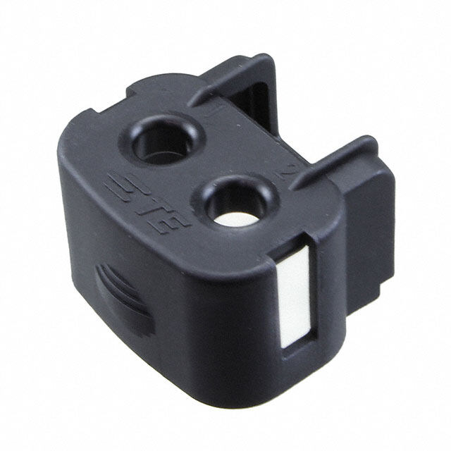
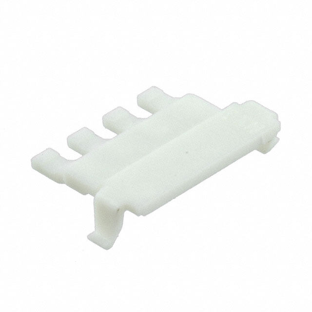
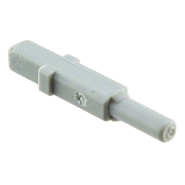
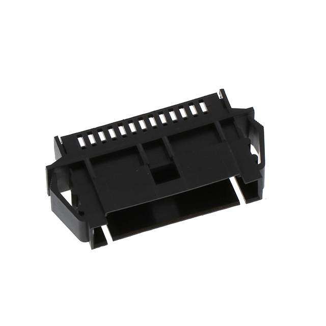
ICGOO在线商城 > 连接器,互连器件 > 矩形连接器 - 配件 > ST40X-BS1(6.8)
- 型号: ST40X-BS1(6.8)
- 制造商: Hirose Electric
- 库位|库存: xxxx|xxxx
- 要求:
| 数量阶梯 | 香港交货 | 国内含税 |
| +xxxx | $xxxx | ¥xxxx |
查看当月历史价格
查看今年历史价格
ST40X-BS1(6.8)产品简介:
ICGOO电子元器件商城为您提供ST40X-BS1(6.8)由Hirose Electric设计生产,在icgoo商城现货销售,并且可以通过原厂、代理商等渠道进行代购。 ST40X-BS1(6.8)价格参考¥2.55-¥5.13。Hirose ElectricST40X-BS1(6.8)封装/规格:矩形连接器 - 配件, 。您可以下载ST40X-BS1(6.8)参考资料、Datasheet数据手册功能说明书,资料中有ST40X-BS1(6.8) 详细功能的应用电路图电压和使用方法及教程。
| 参数 | 数值 |
| 产品目录 | |
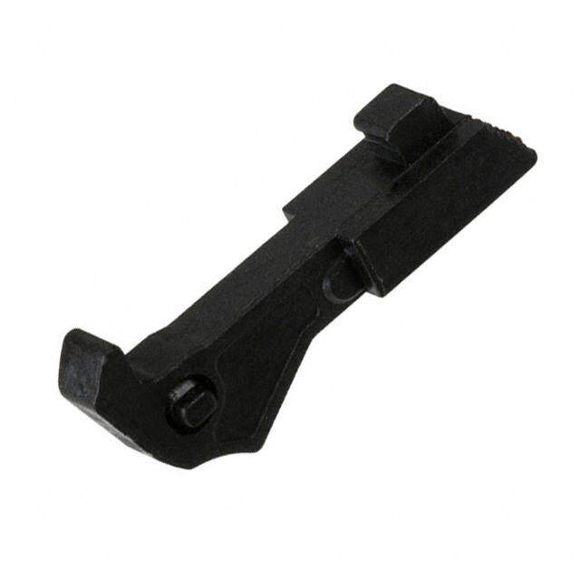
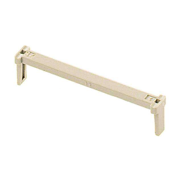
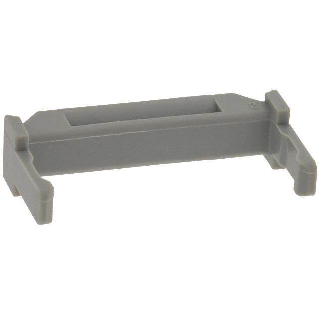
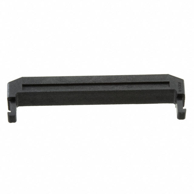
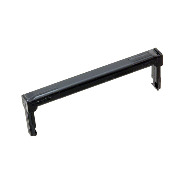
| 描述 | CONN CABLE BUSHING 6.8MMI/O 连接器 CABLE BUSHING 6.8MM FOR ST SERIES |
| 产品分类 | |
| 品牌 | Hirose Connector |
| 产品手册 | |
| 产品图片 |
|
| rohs | 符合RoHS无铅 / 符合限制有害物质指令(RoHS)规范要求 |
| 产品系列 | Hirose Connector ST40X-BS1(6.8)ST |
| 数据手册 | |
| 产品型号 | ST40X-BS1(6.8) |
| 产品 | |
| 产品培训模块 | http://www.digikey.cn/PTM/IndividualPTM.page?site=cn&lang=zhs&ptm=3497 |
| 产品目录绘图 |
|
| 产品目录页面 | |
| 产品种类 | I/O 连接器 |
| 位置数量 | - |
| 其它名称 | *ST40X-BS1(6.8) |
| 商标 | Hirose Connector |
| 型式 | - |
| 外壳材料 | - |
| 安装风格 | - |
| 工厂包装数量 | 1 |
| 标准包装 | 100 |
| 特性 | - |
| 特点 | 6.8 mm Cable Bushing |
| 特色产品 | http://www.digikey.cn/product-highlights/zh/hirose-st-series/52105 |
| 电压额定值 | - |
| 电流额定值 | - |
| 电缆直径 | 6.8 mm |
| 端口数量 | - |
| 端接类型 | - |
| 系列 | ST |
| 节距 | - |
| 触点材料 | - |
| 触点电镀 | - |
| 配件类型 | 套管 |
| 配套使用产品/相关产品 | ST 系列 |
| 针脚数 | - |
| 附件 | Cable Bushing |


- 商务部:美国ITC正式对集成电路等产品启动337调查
- 曝三星4nm工艺存在良率问题 高通将骁龙8 Gen1或转产台积电
- 太阳诱电将投资9.5亿元在常州建新厂生产MLCC 预计2023年完工
- 英特尔发布欧洲新工厂建设计划 深化IDM 2.0 战略
- 台积电先进制程称霸业界 有大客户加持明年业绩稳了
- 达到5530亿美元!SIA预计今年全球半导体销售额将创下新高
- 英特尔拟将自动驾驶子公司Mobileye上市 估值或超500亿美元
- 三星加码芯片和SET,合并消费电子和移动部门,撤换高东真等 CEO
- 三星电子宣布重大人事变动 还合并消费电子和移动部门
- 海关总署:前11个月进口集成电路产品价值2.52万亿元 增长14.8%

PDF Datasheet 数据手册内容提取
Interface Connectors for Portable Terminal Devices ST Series Strong locking mechanism Right Mating axial direction d. Left e 49N max. v r Top e s e R s ht g Overview Ri All Tdehsei gSnTe dS feorri euss ein atesr fIancpeu tc/Oountnpeuct to(Ir/Os )a rceo nsnpeecctiofircsa ollny Bottom Fig.1 D. portable information devices. They feature a unique T Prevention against reversed or angle insertion L structure with high strength which resists deformation O., and helps to prevent improper mating. C 3.0 mm height and 0.5 mm contact pitch connector C prevents EMI as well. RI The ST Series can be used in wide range of applications T Polarization keys C such as DSC, PDA, laptop PCs, cellular phones, etc. E L Contacts are not damaged! E Features E S 1. Strong locking mechanism O R To assure continuous reliability of the connection in HI an unpredictable consumer environment, mated 8 1 connectors will withstand pull force of 49N max. 0 2 applied in any direction. (Fig.1) ht 2. Prevention against reversed or angle g ri insertion y p o Multiple polarization keys will not allow incorrect Fig.2 C 8 insertion of the mating plug. 1 In addition, contacts will not be damaged when the user Plug variations 0 2 attempts to insert only the corner of the mating plug. (Fig.2) 1. Identification surface c. 3. Optimal I/F for Small Devices e D Plugs are 8 mm in height and 20 mm long (including covers), which is appropriate for small devices. Receptacles feature the low height of 3 mm and the Reverse plug contact pitch of 0.5 mm. Their small size saves Identification surface valuable space and contributes to a smaller device set. 4. Multiple Variations A wide variations is available for supporting different types of peripheral devices. Examples include shielded Standard plug plugs for data communication, non-shielded plugs for Fig.3 power charge, reversed plug types as shown in Fig.3 and cradle type connectors. 5. Cable Options This connector uses a solder type termination, which allows you to apply flexible cable types. Applications Digital Still Cameras, Personal Digital Assistance, Notebook computers, Cellular phones, Smart phones and other portable devices requiring high reliability small size input/output connection. Ipnl ecaassee sc ownhtaecret ath ceo ampppalincya trieopnr ewsielln dteamtivaen fdo ar fhuirgthh eler vineflo orfm raetliiaobni.lity, such as automotive, 2016.9④ 1
ST Series●Interface Connectors for Portable Terminal Devices Product Specifications Current rating 0.5A (1 A max. can be carried via 4 random contacts) Operating temperature range : -30ç to +80ç Rating Voltage rating 100V AC Storage temperature range : -40ç to +85ç (Note) Characteristic Specification Conditions 11. Contact resistance 60mø max. 100mA DC 12. Insulation resistance 1,000Mø min. 250V DC 13. Dielectric withstanding voltage No flashover or insulation breakdown. 350V AC/ 1 minute 14. Mating/un-mating forces Mating : 29.4N max. With corresponding connector. 15. Durability Contact resistance : 100mø max. 10,000 cycles (mating/un-mating) 16. Shock Acceleration of 490 m/s2, 11 ms duration, sine half-wave No electrical discontinuity of 10µ sec. max. waveform, 3 cycles in each of the 3 axis. d. Temperature : -55ç ➝ +5ç to +35ç ➝ +85ç ➝ +5ç to +35ç e Contact resistance : 100mø max. v 17. Temperature cycle Time (Minutes) : -30 ➝ +5 ➝ +30 ➝ +5 er Insulation resistance : 1,000Mø min. s 5 cycles e R 5±1% salt water solution at 35±3ç for 48 hours, after s 18. Salt spray No corrosions washing without salt, leave for 24 hours at room temperature ht g 19. Lock strength Fully inserted and locked corresponding connector. Ri No physical damage or electrical failure. Pull force : 49N max. applied in each of the 4 axis. All 10. Vibration Frequency : 10 to 55 Hz, single amplitude of 0.75mm, 2 D. No electrical discontinuity of 10µ sec. max. hours, 3 axis. T L Note: Includes temperature rise caused by current flow. O., C Materials / Finish C RI ● Receptacles and cradles T C Component Material Finish Remarks E L Insulator Thermoplastic compound, glass reinforced Color: Black UL94V-0 E E Contacts Copper alloy Contact area: Gold plated ------------------- S O Shield Stainless steel Tin alloy plating ------------------- R 8 HI ● Plugs 1 0 Component Material Finish Remarks 2 ht Insulator Thermoplastic compound, glass reinforced Color: Black UL94V-0 g ri Contacts Copper alloy Contact area: Gold plated ------------------- y p o Shield Stainless steel ------------------- ------------------- C 8 Cover Thermoplastic compound, glass reinforced ------------------- UL94V-0 1 0 2 1. Product Number Structure c. e Refer to the chart below when determining the product specifications from the product number. D Please select from the product numbers listed in this catalog when placing orders. ● Receptacles ST 60 - 18 P (30) q Series name : ST w Termination type q w r t u 60 : Right angle SMT 40 : Solder type ● Plugs 80 : Cradle, vertical, SMT e Shield X : With shield ST 40 X- 18 S- CVR (30) Blank : Without shield q w e r t y u r Number of contacts t Contact type P : Male contact (Receptacle) ● Plug - Cradle type S : Female contact (Plug) y Plug type ST 80 X- 18 S (30) CV : Standard type, for top PCB mount q w e r t u CVR : Reverse type, for bottom PCB mount CV1 : For larger diameter cables u RoHS compliant : (30) 2
ST Series●Interface Connectors for Portable Terminal Devices Receptacle Recommended PCB mounting pattern 10 pos. 10.5 4.5 (cid:41)(cid:35)(cid:42) (cid:69)(cid:50)(cid:37)(cid:35)(cid:42) 0.5 0.18 (cid:37)(cid:35)(cid:40) (cid:46) (cid:43) (cid:43)(cid:38)(cid:35) (cid:38)(cid:35)(cid:40)(cid:35)(cid:38) (cid:38)(cid:35) 6.47 (cid:40)(cid:35)(cid:38)(cid:98)(cid:94)(cid:99)(cid:39)(cid:35)(cid:44) (cid:38)(cid:35)(cid:46)(cid:39)(cid:35)(cid:45) (119.5.2) (0.58) (cid:71)(cid:37)(cid:35)(cid:40)(cid:29)(cid:73)(cid:93)(cid:103)(cid:100)(cid:106)(cid:92)(cid:93)(cid:21)(cid:93)(cid:100)(cid:97)(cid:90)(cid:30) (cid:38)(cid:37)(cid:41)(cid:35)(cid:38) (cid:38) (cid:37)(cid:38)(cid:35)(cid:35)(cid:71)(cid:43)(cid:46)(cid:37)(cid:35)(cid:45)(cid:42) No.1 No.10 d. Part No. HRS No. Packaging RoHS 4)3 e ST60 ( v ST60-10P(30) 241-0022-5 30 1,500pcs/reel ™ r se 0.3 1.5 75 e 10.1 (4.4) 0. R s 18 pos. ht g Recommended PCB Ri 14.5 mounting pattern D. All 0.58.50.18 0.58.5 0.3(Land) T 69 O., L 6.97.5 11.1. 283.6 CTRIC C No.11135..25No.18 (0.58) 3.R2.70.3 R0.85 6.6(Lan1d) 01..690.9((TL2.harnodu)ghP ChoBl ee)dge E 14.1 EL ST60 (4)3 SE ST6P0a-r1t 8NPo(.30) 241H-0R0S1 N1-o9. 30 1,P5a0c0kpacgsi/nregel Ro™HS 14.1 0.3 14..54 0.75 O R HI 24 pos. 8 1 0 Recommended PCB 2 17.5 ht 11.5 mounting pattern g 0.5 0.18 11.5 yri 0.50.3(Land) p 9 1.2018 Co (1168..25) 6.9(0.58) 7.5 3.12.71.6RR001...385 9.6(La1nd) 10.0.92.96((L2.83.6Tahnrodu)PgCh Bh oeldeg)e c. No.1 No.24 17.1 e D ST60 (4)3 Part No. HRS No. Packaging RoHS 0.3 1.5 5 ST60-24P(30) 241-0003-0 30 1,500pcs/reel ™ 17.1 4.4 0.7 36 pos. Recommended PCB mounting pattern 19 0.5 12295 0.18 3.653.251.72.1 0.5 2 0.35(Land) 1.45 3.05 PCB edge 35 2.45(Land) 0.7(Through hole) 77.5 R0.R1 294.2.65 1.82.35 2(Land) (26) 8) 5 23.5 (0. Part No. HRS No. Packaging RoHS No.1 No.36 ST60-36P(30) 241-0033-1 30 1,500pcs/reel ™ ST60 4.06)3 0.3 ( 1.5 5 24.6 5 0.7 3
ST Series●Interface Connectors for Portable Terminal Devices 36 pos. reverse type Recommended PCB mounting pattern 19 1.72.1 0.5 20.35(Land) 1.45 5 1295 6525 3.0 PCB edge 0.5 2 0.18 3.3. 35 2.45(Land) 0.7(Through hole) R0.R1 9.25 835 2(Land) 77.5 24.6 1.2. (26) 8) 5 23.5 0. ( erved. ST6P0a-3rt6 NPRo.(30) 241H-0R0S3 N6-o0. 30 1,P5a0c0kpacgsi/nregel Ro™HS STN60o.36 No.01.3 (4.06)3 1.5 5 s 24.6 7 e 5 0. R s ht g Ri Plug – cradle type(Horizontal) All 18 pos. 13.78 D. T L O., 17 Recommended PCB C RIC No.1815.8No.1 1.475 5 mounting pattern ght 2018 HIROSE ELECT ST6P0aXr-t1 N8So(.30) 241H-0R0S2 N8-o1. 30 9P0a0cpkcasg/rinegel Ro™HS 01.11158514...55.0655.51.5 Ø10.3.20.91.2551.3752.251.35 3.059.05C1o.(13.65)5nn3e.c5t7or5 0p.o21.475s50.051.8itio1.5(hole)0.752.9nin1g.7 0(.R(310.2R71(2L50).Pa.861=n140.d.5552)4.5.5)55 0.932..15PCØ3.575B11.75. 5e(3.85(max)dge7.95(min) 0.85(Through hole)1.45(Land) pyri hole) o C 8 1 0 2 36 pos. 1. c. e D 24.25 27.5 5 5) 7 9 No.36 No.1 1.4 (2. 222.605 0.25 1.375 4.4750.251.4750.75 Ø1.3 055) 9.3.6 Recommended PCB 94(1 mounting pattern Part No. HRS No. Packaging RoHS 0.15 0.5 0.1. ST60X-36S(30) 241-0035-7 30 900pcs/reel ™ 19 26 24.95 24.95 1.5 3.1 19 2.5 0.5 2 0.32(Land) 2.1ØCp1.oo7(0.05snhiontlieoe)nctinogr 22.05 PCB ed0.9g1.25e 5(max)4.4757.75(min)0.85(Through hole)1.45(Land) 5 3. 4
ST Series●Interface Connectors for Portable Terminal Devices Plug – cradle type(Vertical) Recommended PCB mounting pattern 10 pos. 11.3 11.3 1.5 2.25 4 2.4ole) h Ø1.6(hRoR0le0.2).455 0(L.a5nd) 1 2 2 0.5(Through 0.9(Land) 16 6 11.2 88 2. 4 8.4. 2.6 2.25 ed. 7.8NN5.5oo..11 ST80 1 0.2 NNoo..1906 Ø1.3 0.152.62.6RR00.5.3 1.17511014..32 22..510.6(Through hole)1(Land) erv Part No. HRS No. Packaging RoHS N1o.2 No.10 9.6 1.150.25 s 1.75 Re ST80X-10S(30) 241-0030-3 30 400pcs/reel ™ 4 s ht g Ri All D. 1.510.3 T L 18 pos. Recommended PCB O., mounting pattern C 14.9 14.9 C 1.5 8 ECTRI (18) 2.825 0.5(Land)1.6 31.75 Ø1.55(hole) L E 27.6 8 ht 2018 HIROSE Part No. HRS No. Packaging RoHS 7.8NN6oo..21No4.ST80.125321.1785805.7.2 NNRNo2o.1.o.11.8817 5.59.61.11.11Ø1.3.50.250.152.8752.8258.2.8750.9(Land)0.5(Through hole) 2.24 41121.34528...5627 RR0.205.45Ø4.5(hole) g ri ST80X-18S(30) 241-0020-0 30 400 pcs/reel ™ y p o 2 C 1.5 8 13.6 1 14.2 0 2 Recommended PCB 1. 24 pos. mounting pattern c. De d) ugh hole) 2.4 171.12 R0.25 R0.45Ø1.60(h.5ol(e)Land) n o 0.75 17.2 9(La 5(Thr 02.75 51.25 1.5 0. 0. A 2.62.6 4.88.8 (2220197.1.79) 1(Land) 0.6(Through hole) 41..2212..5551 95..1611177651..22 RR0.30.5Ø4(hole) 5.25 27 No.2 1 0.2 No.24 5 Part No. HRS No. Packaging RoHS No.1 No.24 1.3 0.1 ST80X-24S(30) 241-0037-2 30 400 pcs/reel ™ ST80 67.8 Ø 2.6 No.1 A 51.75 NoR.213.8 69.6 1.150.25 4.15 11 5.6 9.6 6 1. A 1.5 1.25 16.2 17.2 5
ST Series●Interface Connectors for Portable Terminal Devices Plug 10 pos. (Non-shielded type) 16 7 5 9. 1 6 16 Part No. HRS No. Packaging RoHS d. ST40-10S-CV(30) 241-0021-2 30 1 ™ e rv No.10 No.1 e s e 10 pos. (Reverse, non-shielded type) R s ht 16 7 g Ri All D. 9.5 T 1 L O., C 6 C RI 16 T C E Part No. HRS No. Packaging RoHS EL ST40-10S-CVR(30) 241-0040-7 30 1 ™ E No.10 No.1 S O R 10 pos. (Shielded type) HI 8 16 7 1 0 2 ht g yri 19.5 p o C 8 1 6 0 2 1. 16 c. e D Part No. HRS No. Packaging RoHS ST40X-10S-CV(30) 241-0041-0 30 1 ™ No.10 No.1 10 pos. (Reverse, shielded type) 16 7 5 9. 1 6 16 Part No. HRS No. Packaging RoHS ST40X-10S-CVR(30) 241-0029-4 30 1 ™ No.10 No.1 6
ST Series●Interface Connectors for Portable Terminal Devices 18 pos. (Shielded type) 18 7 0 2 5 5. 18 Part No. HRS No. Packaging RoHS ST40X-18S-CV(30) 241-0012-1 30 1 ™ d. e No.18 No.1 v r e s e 18 pos. (Reverse, shielded type) R s 18 7 ht g Ri All D. 20 T L O., C 5 C 5. RI 18 T C E Part No. HRS No. Packaging RoHS EL ST40X-18S-CVR(30) 241-0016-2 30 1 ™ E S No.18 No.1 O R 24 pos. (Shielded type) HI 8 21 7 1 0 2 ht g yri 20 p o C 8 1 5 0 5. 2 1. 21 c. e D Part No. HRS No. Packaging RoHS ST40X-24S-CV(30) 241-0004-3 30 1 ™ No.24 No.1 24 pos. (Shielded type) 21 9 0) 0) 1 1 1( ( 0. 2 5 5. 21 Part No. HRS No. Packaging RoHS No.24 No.1 ST40X-24S-CV1(30) 241-0023-8 30 1 ™ 7
ST Series●Interface Connectors for Portable Terminal Devices 36 pos. (Shielded type) 30.6 11.4 9 2 7 6. 32.5 7.6 Part No. HRS No. Packaging RoHS ST40X-36S-CV(30) 241-0034-4 30 1 ™ No.36 No.1 Note: Plug assemblies will require additional components. Contact Hirose Electric representative for detailed descriptions and installation instructions. d. e v r e s Packaging Specification e R s Embossed Carrier Tape Dimensions ht Reel Dimensions g Unreeling direction Ri D Part No. A B C D E pcs. / reel All 4 5 ST60-10P(30) 24 ----- 11.5 12 00.5 1,500 D. Ø1.5 2 1.7 ST60-18P(30) 24 ----- 11.5 12 00.5 1,500 T ST60-24P(30) 32 28.4 14.2 12 00.5 1,500 L O., C SSTT6600--3366PP(R3(03)0) 4444 4400..44 2200..22 1122 0000..55 11,,550000 C C ST80X-10S(30) 24 ----- 11.5 16 12.2 0400 B A RI ST80X-18S(30) 44 40.4 20.2 16 12.7 0400 T ST80X-24S(30) 44 40.4 20.2 16 12.7 0400 C E ST60X-18S(30) 32 28.4 14.2 20 4.95 0900 L E ST60X-36S(30) 44 40.4 20.2 20 4.85 0900 E S E O R Recommended Temperature Profile HI (Lead-free soldering compound) 8 Reel Dimensions 1 0 This measurement is performed on 2 ht Unreeling direction (ç) the contact lead section. yrig Pocket 250 224300çç min The temperature profile may vary p 3) 200 due to external conditions such as o 1 180ç C ( the type of cream solder, 018 (Ø382) 115000 150ç manufacturer, and board size. 2 60S 30S Please contact the solder 1. 50 c. manufacturer for their e D specifications. ® 2-6-3,Nakagawa Chuoh,Tsuzuki-Ku,Yokohama-Shi 224-8540,JAPAN TEL: +81-45-620-3526 Fax: +81-45-591-3726 http://www.hirose.com http://www.hirose-connectors.com The characteristics and the specifications contained herein are for reference purpose. Please refer to the latest customer drawings prior to use. 8 The contents of this catalog are current as of date of 09/2016. Contents are subject to change without notice for the purpose of improvements. Powered by TCPDF (www.tcpdf.org)
Mouser Electronics Authorized Distributor Click to View Pricing, Inventory, Delivery & Lifecycle Information: H irose Electric: ST60-24P(50) ST40X-24S-CV(80) ST60-18P(50) ST40X-18S-CV(80) ST40X-CM(4.0) ST40X-18S-CVR(80) ST80X-18S(50) ST40-10S-CV(80) ST60-10P ST40X-24S-CV1(80) ST40X-CM(5.8) ST40X-BS(5.8) ST60X-18S ST40X-10S-CVR(80) ST80X-10S ST60-36P ST40X-36S-CV(80) ST60X-36S ST60-36PR ST80X-24S(50) ST40- 10S-CVR(80) ST40X-10S-CV(80) ST40X-CM(6.8) ST40X-BS(4.0) ST40X-CM(4.0-5.0) ST40X-18S-CV1 ST40X- CM1(6.8) ST40X-BS1(6.8) ST40X-24S-CV(81) ST40X-CM(5.8)/CK-MP(61) ST40X-CM(5.8)/CK-MP ST40X- CM(5.8)/CK-MP(62) ST40X-CM(5.8)/CK-MP(01) ST40X-CM(40-50)/CK-MP(01) ST40X-CM(40-50)/CK-MP ST40X- CM(40-50)/CK-MP(62) ST40X-CM(40-50)/CK-MP(61) ST60-24P(51) ST40X-18S-CV(30) ST80X-10S(30) ST40-10S- CVR(30) ST40X-24S-CV1(30) ST60-24P(30) ST60-18P(30) ST40X-18S-CVR(30) ST40X-10S-CVR(30) ST40X-36S- CV(30) ST60-36P(30) ST40X-18S-CV1(30) ST80X-24S(30) ST40X-10S-CV(30) ST60-10P(30) ST60-36PR(30) ST60X-36S(30) ST60-24P(31) ST40X-24S-CV(31)
.jpg)
 Datasheet下载
.jpg)

